US4719437A - Electrical ground fault receptacle assembly - Google Patents
Electrical ground fault receptacle assembly Download PDFInfo
- Publication number
- US4719437A US4719437A US06/775,361 US77536185A US4719437A US 4719437 A US4719437 A US 4719437A US 77536185 A US77536185 A US 77536185A US 4719437 A US4719437 A US 4719437A
- Authority
- US
- United States
- Prior art keywords
- cross bar
- trip
- ground fault
- pin
- pushbutton
- Prior art date
- Legal status (The legal status is an assumption and is not a legal conclusion. Google has not performed a legal analysis and makes no representation as to the accuracy of the status listed.)
- Expired - Lifetime
Links
Images


Classifications
-
- H—ELECTRICITY
- H01—ELECTRIC ELEMENTS
- H01H—ELECTRIC SWITCHES; RELAYS; SELECTORS; EMERGENCY PROTECTIVE DEVICES
- H01H71/00—Details of the protective switches or relays covered by groups H01H73/00 - H01H83/00
- H01H71/10—Operating or release mechanisms
- H01H71/50—Manual reset mechanisms which may be also used for manual release
- H01H71/58—Manual reset mechanisms which may be also used for manual release actuated by push-button, pull-knob, or slide
-
- H—ELECTRICITY
- H01—ELECTRIC ELEMENTS
- H01H—ELECTRIC SWITCHES; RELAYS; SELECTORS; EMERGENCY PROTECTIVE DEVICES
- H01H71/00—Details of the protective switches or relays covered by groups H01H73/00 - H01H83/00
- H01H71/10—Operating or release mechanisms
- H01H71/12—Automatic release mechanisms with or without manual release
- H01H71/24—Electromagnetic mechanisms
- H01H71/2472—Electromagnetic mechanisms with rotatable armatures
-
- H—ELECTRICITY
- H01—ELECTRIC ELEMENTS
- H01H—ELECTRIC SWITCHES; RELAYS; SELECTORS; EMERGENCY PROTECTIVE DEVICES
- H01H83/00—Protective switches, e.g. circuit-breaking switches, or protective relays operated by abnormal electrical conditions otherwise than solely by excess current
- H01H83/02—Protective switches, e.g. circuit-breaking switches, or protective relays operated by abnormal electrical conditions otherwise than solely by excess current operated by earth fault currents
Definitions
- the present invention relates to a leakage current interruptor, particularly to an improved electrical ground fault receptacle assembly for protecting electric appliances from the hazards of ground fault currents by operation of a ground fault interrupting circuit.
- U.S. Pat. No. 4,084,203 issued to Robert E. D. Dietz etc. on Apr. 11, 1975 shows a receptacle assembly provided with a ground fault circuit interrupter having the size of an ordinary household or commercial junction box.
- This receptacle assembly comprises a ground fault detecting circuit for sensing a ground fault, and a coil and a trip mechanism for separating a protection circuit from the power supply whenever a ground fault occurs.
- This receptacle assembly was constructed so that the ground fault detecting circuit includes two differential transformers to sense a low level ground fault upon occurance of a ground fault, and to feed the ground fault detecting signal to an amplifier, and then to trigger a switching device by means of the amplified signal, thereby preventing damage of an electric appliances by ground fault.
- the trip mechanism installed in this receptacle assembly is comprised so that the carrier member and the armature be coordinated with each other as a independent mechanism spaced away from the trip coil.
- the trip mechanism when the trip mechanism is activated to open the protecting circuit on the occurance of a ground fault, it does not instantly interrupt because the shut-off of excess current depends on the operation and interaction of numerous steps, for example, the arrangement of the coil and the armature, the arrangement of the armature and the carrier, the arrangement of the carrier and the reset switch, and the arrangement of the reset switch and the ring.
- the interaction of each operating component has a tendency to delay the overall function, resulting in less than complete protection of electric appliances. This is especially true since the trip mechanism is very complex in construction.
- the present invention is devised so that the ground fault detecting circuit is activated by a minimum sensing current of the ground fault signal allowing the trip mechanism to instantly interrupt the ground fault current, thereby providing protection to electric appliances.
- the ground fault detecting circuit is provided with two differential transformers to sense a lower level ground fault signal upon the occurance of a short circuit or other electric abnormalities, by applying this signal to the level comparator and the amplifier.
- the level comparator compares the two signals and produces a high level signal at its output while the amplifier amplifies the above ground fault signal. Then the latch circuit latches the high level signal in response to the high level signal of the level comparator and supplies the high level output to the switching device for triggering it into conduction, thereby producing an amplified signal to operate the trip mechanism.
- the trip mechanism is energized by the ground fault current applied to its coil and pulls the operating bar therein. Therefore, the trip cross bar integrally coupled with the above operating bar is rotated in a clockwise direction to be separated from the cross bar connected to it, thereby interrupting the power supply source from the electric appliance.
- An additional object of this invention is to provide the electric ground fault receptacle assembly which is simple in construction and economical to manufacture.
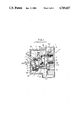
- FIG. 1 is a cross sectional view of the trip mechanism used in the conventional leakage current interrupter.
- FIG. 2 is an exploded perspective view of the electric receptacle assembly in accordance with the preferred embodiment the present invention.
- FIG. 3 is a cross-sectional view taken along the line A--A of FIG. 2.
- FIG. 4 is a view representing the trip mechanism in a locked position.
- FIG. 5 is a view representing the trip mechanism in an open position.
- FIG. 6 is the ground fault detecting circuit under the preferred embodiment of the present invention.
- FIG. 1 shows a conventional trip mechanism utilizing a bimetal switch.
- the receptacle assembly 1 is provided with the fixed contact 21 integrally formed to the case 1' thereof.
- the fixed contact 21 is engaged with the moving contact 20 by means of the contact push plate 4, wherein the moving contact 20 is configurated to always be maintained in the off position by spring 30.
- the contact push plate 4 moves downward along the groove formed in the case 1' by means of and in accordance with the connecting plate 2 and the pressing plate 3 in cooperation with the handle 7 when the handle 7 is in the ON position.
- said plate 4 serves to contact the moving contact 20 with the fixed contact 21.
- the contact push plate 4 is formed to be installed into the groove (not shown) provided within the case 1'.
- the pressing plate 3 of the trip mechanism pressing the contact push plate 4 includes the portion 22 pressing the push plate 4, the projection 23 having a hole and allowing it to be coupled with the connecting plate 2 connected to the projector 9 of the handle 7, and the portion 24 fixed to the projectio 23 and the pin 13 of the stopper 5.
- the stopper 5 is rotated around pin 12 at its center by means of the pressing plate 3 and is interlocked with the jaw portion 16 of the hooking member 6 by projection 17.
- the hooking member 6 coupled with bimetal strip 14 is comprised of the operating portion 25, which presses said member, and the jaw portion 16 for hooking the projection 17 of the stopper 5, and said bimetal strip 14 is always forced in a direction opposite to that of arrow B by the force of the spring 29 with the pin 13 at its center.
- the handle 7 of the trip mechanism is coupled with the connecting plate 2 and is integrally provide with the projection portion 18 to give a displacement to the pressing plate 3 according to the movement of the handle 7.
- the spring 26 installed in the handle 7 is maintained to keep it in the off position.
- the frame 19 there are integrally assembled the pressing plate 3, the connecting plate 2, the stopper 5, the handle 7 and the hooking member 6 along with pin (8, 9, 10 11, 12, 13) and the spring (26, 27, 28, 29).
- the portion represented by the dashed line of FIG. 1 shows the condition in which the moving contact 20 and the fixed contact 21 are connected to each other.
- the projection 17 of the stopper 5 is interlocked with on the jaw portion 16 of the hooking member 6. Such operation of the above assembly is explained in detail below.
- the pressing plate 3 coupled to the handle 7 is moved downwardly along the groove of the frame 19 by means of the connecting plate 2 coupled to the projection 18 of the handle 7. Then the push plate 4 retains the elastic force of spring 30 installed below the moving contact 20, thereby being moved downwardly along the groove formed in the case 1' to contact the moving contact 20 with the fixed contact 21. At this time should one end of the pressing plate 3 make the stopper 5 rotate with the pin at its center, the projection 17 of the stopper 5 is interlocked with the jaw portion 16 of the hooking member 6.
- the trip mechanism used in the conventional leakage current interrupter has a disadvantage in that ground faults can not be instantly interrupted from the protecting circuit and the assembly elements are numerous, thereby making its configuration very complex. Furthermore, as ground faults cannot be instantly interrupted, protection of electric appliance can not be completly guaranteed.
- FIG. 2 shows the electrical receptacle assembly 100 of this invention and additionally shows an exploded view representing the trip mechanism 200 in detail.
- This receptacle assembly 100 includes the case 30' integrally made from synthesized resin.
- This case 30' is provided with the fixed contacts 48, 49 and the spring hooks 50, 51 to which the end of the springs 52 are fixed respectively.
- the center portion of the case 30' has the space 44 for receiving the structural elements of the trip mechanism 200.
- the case 30' is provided with the groove G below the spring hook 50, 51 on both innersides of the space 44, wherein this groove G acts to guide both ends of the pin 39 on which the restoring force is applied according to the operation of the push button 31.
- the push button 31 made from synthesized resin is provided with the projections 40 spaced away from each other on the end surface of said push button. The end of the projection 40 has a gap into which the longitudinal portion of the pin 39 is snugly inserted.
- the cross bar 33 is provided with the moving contact 43, 45 in contact with the fixed contact 48, 49, and the extension 32 which is interlocked with the jaw 42 of trip cross bar 37 during normal operation. Also, the cross bar 33 is integrally provided with the projection 46 having a hole into which the pin 39 is inserted.
- the push button 31 is connected to the cross bar 33 to cooperate with each other. Adjacent to and between the two projections 46 projecting from the upper surface of the cross bar 33, there is provided a groove to support the projection end of the push button 31 and to house spring 41 for applying an elastic force to the push button 31, wherein the elastic force functions maintain a constant upperward pressure against the extension 32 of an opposite direction to the pushing direction of the push button 31.
- the operation portion 36 of the trip mechanism 200 is integrally provided with the solenoid 35 (below referred to the trip coil), the trip cross bar 37 and the frame 57 for supporting them.
- the trip cross bar 37 made from synthesized resin is integrally provided with the jaw 42 which engages with the extension 32 of the cross bar 33, the stopper 47 limiting rotation, and a groove into which the operating pin 27 of the solenoid 35 is inserted.
- the frame 57 is bent into a "C" shape to house the trip coil 35 therein and the supporter 55 for mounting the trip cross bar 37.
- One side of supporter 55 has the step portion 56 limiting the downward operation of the this cross bar 37.
- the printed circuit board 34 is provided with the frame 57 of the operation portion 36 of the trip mechanism 200 soldered to it and the ground fault detecting circuit 300(hereafter explained in detail) for operating the solenoid.
- the outer cover 54 has rectangular hole 53 for inserting the push button 31.
- FIG. 3 is a cross-sectional view along line A--A of FIG. 2 representing the trip mechanism 200 in a locked position.
- the cross bar 33 and the trip cross bar 37 are engaged and maintained by the elastic force of both spring 52 positioned between the pin 39 and the spring hooks 50, 51. Therefore, the fixed contact 48, 49 and the moving contact will touch each other in the on position.
- the grooves G formed with the space 44 of the case 30' receive the springs 52 and both ends of the pin 39 therein.
- the extension 32 of the cross bar 33 pushes the jaw 42 of the trip cross bar 37 and at the moment the extension is engaged with the jaw 42, to which the elastic force of the spring 58 is applied, the jaw 42 is rotated in the direction B of the arrow around the pin 60 which is inserted across the support 55 of the frame 57. Then if the finger is taken off the push button 31, the extention 32 of the cross bar 33 is interlocked with the jaw 42, while the cross bar 33 is rotated in the direction C of the arrow by the elastic force of the spring 52, to thereby couple the moving contact 43 with the fixed contact 49.
- This operation is the process by which the trip mechanism of this invention is connected with the protection circuit.
- the ground fault detecting circuit 300 senses the ground fault signal and then this signal voltage is applied to the trip coil 35.
- the trip coil 35 is energized to produce a magnetic force so that the operating pin 38 is drawn into therein in direction F of the arrow against the elastic force of the spring 58.
- the trip cross bar 37 connected to one end of the operating pin 38 rotates around the pin 60 and is released from the extension 32 as shown in the solid line of FIG. 5 so that the extension 32 of the cross bar 33 is disconnected from the jaw 42 of the trip cross bar 37.
- the cross bar 33 moves backward in the direction
- the cross bar 37 returns to the position represented in the dotted line of FIG. 5 by the restoring force of the spring 58.
- the ground fault detecting circuit 300 is provided with the first and the second transformers 303 and 304 to make the power supply bus line 301 and 302 pass through their toroidal cores.
- the rectifier 305 has one end A' connected to the load line 301 of the power supply bus line and the other end B' connected to the ground line 302 of the power supply bus line. This rectifier 305 regulates the output of positive voltage at the terminal D' and negative voltage at the terminal C'.
- the first differential transformer 303 has a primary coil one end of which is connected to the load line of the rectifier 305 and the other connected through the resistor 318 to the ground line of the rectifier 305 and then through the varistor 319 to the load line of the rectifier 305.
- the second differential transformer 304 has a second coil in which at both ends of the second coil, the capacitor 320 and the load resistor 321 are connected in parallel to each other, and also the current direction control diodes 322 and 323 are connected in parallel to each other, but with their polarities in opposite directions.
- the full wave rectified voltage output from the rectified 305 is applied to the voltage regulator 307.
- the regulator 307 supplies a predetermined voltage to the invert terminal of the level comparator 308.
- the level comparator 308 compares the signal of the second differential transformer 304 received from its non-invert terminal with the signal from the voltage regulator 307, to thereby supply the high level or the low level signal to the latch circuit 309.
- the latch circuit 309 applies the rated high level or low level signal the to gate of the SCR 310. While the signal of the second differential transformer 304 is applied through the resistor 324 to the amplifier 311. Then the amplified signal is applied through the capacitor 312 to the terminal c' of the rectifier 305 and then is supplied to the trip coil 35.
- the SCR 310 has the anode connected to the front end of the resistor 306 and the cathode connected to the terminal c' of the rectifier 305. Between the anode of the SCR 310 and the terminal c' of the rectifier 305 the capacitor 314 and the resistor 315 are connected in serial to each other.
- the capacitor 316 has one end connected to the rear of the resistor 306 and other end connected to the terminal c'.
- One end of the capacitor 313 is connected between the latch circuit 309 and the gate of the SCR 310.
- the capacitor 317 has one end connected to the latch circuit and other end connected to the terminal c'.
- the ground fault detecting circuit 300 includes the second differential transformer for sensing the low level ground fault signal and applies this detecting signal to the amplifier 311, while this detecting signal is applied to the non-inverting terminal of the level comparator 308.
- the level comparator 308 compares this detecting signal with the voltage predetermined by the voltage regulator 307. Then if the ground fault signal is greater than the predetermined voltage signal, the comparator 38 applies the high level signal to the latch circuit 309.
- the latch circuit 309 latches the high level signal responsive to said high level signal and again supplies the high level signal to the gate of the SCR 310, thereby triggering the SCR 310 into operation.
- the amplified signal from the amplifier 311 energizes the trip coil 35 and the trip mechanism 200 disengages the power protecting circuit from the power supply source.
- the invention is to provide a receptacle assembly comprised of a simple configuration of a trip mechanism as a leakage interruptor. Therefore, this invention has a marked advantage in that the ground fault detecting circuit and the trip mechanism can instantly interrupt ground faults from the protection circuit by instantaneously responding to current leakages thereby guaranteed maximum protection from ground faults.
Abstract
Description
Claims (4)
Applications Claiming Priority (2)
| Application Number | Priority Date | Filing Date | Title |
|---|---|---|---|
| KR5530[U] | 1985-03-06 | ||
| KR850005530 | 1985-03-06 |
Publications (1)
| Publication Number | Publication Date |
|---|---|
| US4719437A true US4719437A (en) | 1988-01-12 |
Family
ID=19242100
Family Applications (1)
| Application Number | Title | Priority Date | Filing Date |
|---|---|---|---|
| US06/775,361 Expired - Lifetime US4719437A (en) | 1985-03-06 | 1985-09-12 | Electrical ground fault receptacle assembly |
Country Status (1)
| Country | Link |
|---|---|
| US (1) | US4719437A (en) |
Cited By (37)
| Publication number | Priority date | Publication date | Assignee | Title |
|---|---|---|---|---|
| US4893101A (en) * | 1988-10-21 | 1990-01-09 | Ericson Manufacturing Company | Resettable ground fault circuit interrupter |
| GB2247354A (en) * | 1990-08-06 | 1992-02-26 | Tower Mfg Corp | Appliance leakage current interrupters |
| US5223810A (en) * | 1992-08-20 | 1993-06-29 | General Electric Company | Trip-reset mechanism for GFCI receptacle |
| US5229730A (en) * | 1991-08-16 | 1993-07-20 | Technology Research Corporation | Resettable circuit interrupter |
| US5264811A (en) * | 1991-09-30 | 1993-11-23 | Uchiya Thermostat Co. | Mechanical latch device and relay including the mechanical latch device |
| US5457444A (en) * | 1991-07-22 | 1995-10-10 | Pdl Holdings Limited | Switching mechanism |
| US5459444A (en) * | 1991-05-16 | 1995-10-17 | Felchar Manufacturing Corporation | Circuit breaker for use in wall mounted plug |
| US5517165A (en) * | 1991-07-22 | 1996-05-14 | Pdl Holdings Limited | Switch mechanism |
| US5990769A (en) * | 1997-10-23 | 1999-11-23 | Tam; Clement Pui-Yin | Switchable electric outlet adaptor |
| US6246558B1 (en) | 1998-08-24 | 2001-06-12 | Leviton Manufacturing Company | Circuit interrupting device with reverse wiring protection |
| US20020006022A1 (en) * | 1998-08-24 | 2002-01-17 | Disalvo Nicholas L. | Circuit breaker with independent trip and reset lockout |
| US20020071228A1 (en) * | 1998-08-24 | 2002-06-13 | Steve Campolo | Circuit interrupting device with reset lockout and reverse wiring protection and method of manufacture |
| US20030086219A1 (en) * | 2001-03-21 | 2003-05-08 | Richard Bernstein | GFCI reset lockout |
| US6657834B2 (en) | 1998-08-24 | 2003-12-02 | Leviton Manufacturing Co., Inc. | Reset lockout for circuit interrupting device |
| US6671145B2 (en) | 2001-03-20 | 2003-12-30 | Leviton Manufacturing Co., Inc. | Reset lockout mechanism and independent trip mechanism for center latch circuit interrupting device |
| US20040070897A1 (en) * | 2002-10-09 | 2004-04-15 | Zhixin Wu | Ground fault circuit interrupter with reverse wiring protection |
| US20040070474A1 (en) * | 2002-10-09 | 2004-04-15 | Zhixin Wu | Ground fault circuit interrupter with reverse wiring protection |
| US20040090722A1 (en) * | 2001-03-21 | 2004-05-13 | Ulrich Richard J. | Alci with reset lockout and independent trip |
| US20040095696A1 (en) * | 1998-08-24 | 2004-05-20 | Ziegler William R. | Circuit interrupting system with independent trip and reset lockout |
| US6771152B2 (en) | 2001-03-21 | 2004-08-03 | Leviton Manufacturing Co., Inc. | Pivot point reset lockout mechanism for a ground for fault circuit interrupter |
| US20040218316A1 (en) * | 2003-02-03 | 2004-11-04 | Frantz Germain | Circuit interrupting device and system utilizing electromechanical reset |
| US20040223272A1 (en) * | 2003-02-03 | 2004-11-11 | Frantz Germain | Circuit interrupting device and system utilizing bridge contact mechanism and reset lockout |
| US20050063110A1 (en) * | 1998-08-24 | 2005-03-24 | Disalvo Nicholas L. | Circuit interrupting device with reverse wiring protection |
| US20050140477A1 (en) * | 1998-08-24 | 2005-06-30 | Frantz Germain | Reset lockout mechanism and independent trip mechanism for center latch circuit interrupting device |
| US20050286183A1 (en) * | 2004-04-08 | 2005-12-29 | Frantz Germain | Circuit interrupting device with a single test-reset button |
| US7031125B2 (en) | 2000-10-16 | 2006-04-18 | Leviton Manufacturing Co., Inc. | Reset lockout for sliding latch GFCI |
| US20060198071A1 (en) * | 1998-08-24 | 2006-09-07 | Steve Campolo | Circuit interrupting device with reset lockout and reverse wiring protection and method of manufacture |
| US20070014058A1 (en) * | 2003-07-03 | 2007-01-18 | Chan David Y | Neutral switch test mechanism for a circuit interrupter |
| US20070049077A1 (en) * | 2005-08-31 | 2007-03-01 | Frantz Germain | Electrical wiring devices with a protective shutter |
| US20070235300A1 (en) * | 2002-12-30 | 2007-10-11 | Frantz Germain | Ground fault circuit interrupter with blocking member |
| US20090026980A1 (en) * | 2007-07-26 | 2009-01-29 | Leviton Manufacturing Co., Inc. | Dimming system powered by two current sources and having an operation indicator module |
| US20110102953A1 (en) * | 2002-05-09 | 2011-05-05 | Nelson Bonilla | GFCI that cannot be reset until wired correctly on line side and power is applied |
| US7944331B2 (en) | 2003-02-03 | 2011-05-17 | Leviton Manufacturing Co., Inc. | Circuit interrupting device with reverse wiring protection |
| US20110149453A1 (en) * | 2008-07-07 | 2011-06-23 | Leviton Manufacturing Company, Inc. | Fault circuit interrupter device |
| US20110216546A1 (en) * | 2010-03-03 | 2011-09-08 | Leviton Manufacturing Co., Inc. | Lampholder with occupancy sensor |
| US8444309B2 (en) | 2010-08-13 | 2013-05-21 | Leviton Manufacturing Company, Inc. | Wiring device with illumination |
| US8526144B2 (en) | 2011-03-31 | 2013-09-03 | Leviton Manufacturing Company, Inc. | Reset lockout with grounded neutral test |
Citations (3)
| Publication number | Priority date | Publication date | Assignee | Title |
|---|---|---|---|---|
| DE613477C (en) * | 1935-05-20 | Wilhelm Leyhausen | Electromagnetic overcurrent switch | |
| US4084203A (en) * | 1975-04-14 | 1978-04-11 | Square D Company | Ground fault receptacle |
| US4506246A (en) * | 1983-05-09 | 1985-03-19 | Square D Company | Interlock scheme for high amperage molded case circuit breaker |
-
1985
- 1985-09-12 US US06/775,361 patent/US4719437A/en not_active Expired - Lifetime
Patent Citations (3)
| Publication number | Priority date | Publication date | Assignee | Title |
|---|---|---|---|---|
| DE613477C (en) * | 1935-05-20 | Wilhelm Leyhausen | Electromagnetic overcurrent switch | |
| US4084203A (en) * | 1975-04-14 | 1978-04-11 | Square D Company | Ground fault receptacle |
| US4506246A (en) * | 1983-05-09 | 1985-03-19 | Square D Company | Interlock scheme for high amperage molded case circuit breaker |
Cited By (91)
| Publication number | Priority date | Publication date | Assignee | Title |
|---|---|---|---|---|
| US4893101A (en) * | 1988-10-21 | 1990-01-09 | Ericson Manufacturing Company | Resettable ground fault circuit interrupter |
| GB2247354A (en) * | 1990-08-06 | 1992-02-26 | Tower Mfg Corp | Appliance leakage current interrupters |
| US5148344A (en) * | 1990-08-06 | 1992-09-15 | Tower Manufacturing Corporation | Appliance leakage current interrupter |
| GB2247354B (en) * | 1990-08-06 | 1995-04-05 | Tower Mfg Corp | Appliance leakage current interrupter |
| US5459444A (en) * | 1991-05-16 | 1995-10-17 | Felchar Manufacturing Corporation | Circuit breaker for use in wall mounted plug |
| US5457444A (en) * | 1991-07-22 | 1995-10-10 | Pdl Holdings Limited | Switching mechanism |
| AU665551B2 (en) * | 1991-07-22 | 1996-01-11 | Pdl Holdings Limited | Switch mechanism |
| US5517165A (en) * | 1991-07-22 | 1996-05-14 | Pdl Holdings Limited | Switch mechanism |
| US5229730A (en) * | 1991-08-16 | 1993-07-20 | Technology Research Corporation | Resettable circuit interrupter |
| US5264811A (en) * | 1991-09-30 | 1993-11-23 | Uchiya Thermostat Co. | Mechanical latch device and relay including the mechanical latch device |
| US5223810A (en) * | 1992-08-20 | 1993-06-29 | General Electric Company | Trip-reset mechanism for GFCI receptacle |
| US5990769A (en) * | 1997-10-23 | 1999-11-23 | Tam; Clement Pui-Yin | Switchable electric outlet adaptor |
| US20050002138A1 (en) * | 1998-08-24 | 2005-01-06 | Frantz Germain | Ground fault circuit interrupter with locking reset button |
| US7098761B2 (en) | 1998-08-24 | 2006-08-29 | Leviton Manufacturing Co., Inc. | Reset lockout mechanism and independent trip mechanism for center latch circuit interrupting device |
| US20020071228A1 (en) * | 1998-08-24 | 2002-06-13 | Steve Campolo | Circuit interrupting device with reset lockout and reverse wiring protection and method of manufacture |
| US6437953B2 (en) | 1998-08-24 | 2002-08-20 | Leviton Manufacturing Co., Inc. | Circuit interrupting device with reverse wiring protection |
| US7400479B2 (en) | 1998-08-24 | 2008-07-15 | Leviton Manufacturing Co., Inc. | Reset lockout for circuit interrupting device |
| US6657834B2 (en) | 1998-08-24 | 2003-12-02 | Leviton Manufacturing Co., Inc. | Reset lockout for circuit interrupting device |
| US7400477B2 (en) | 1998-08-24 | 2008-07-15 | Leviton Manufacturing Co., Inc. | Method of distribution of a circuit interrupting device with reset lockout and reverse wiring protection |
| US6693779B2 (en) | 1998-08-24 | 2004-02-17 | Leviton Manufacturing Co., Inc. | IDCI with reset lockout and independent trip |
| US6717782B2 (en) * | 1998-08-24 | 2004-04-06 | Leviton Manufacturing Co., Inc. | Circuit breaker with independent trip and reset lockout |
| US6246558B1 (en) | 1998-08-24 | 2001-06-12 | Leviton Manufacturing Company | Circuit interrupting device with reverse wiring protection |
| US8130480B2 (en) | 1998-08-24 | 2012-03-06 | Leviton Manufactuing Co., Inc. | Circuit interrupting device with reset lockout |
| US7378927B2 (en) * | 1998-08-24 | 2008-05-27 | Leviton Manufacturing Co., Inc. | Circuit breaker with independent trip and reset lockout |
| US20040095696A1 (en) * | 1998-08-24 | 2004-05-20 | Ziegler William R. | Circuit interrupting system with independent trip and reset lockout |
| US20040108923A1 (en) * | 1998-08-24 | 2004-06-10 | Disalvo Nicholas L. | Reset lockout for circuit interrupting device |
| US7365621B2 (en) | 1998-08-24 | 2008-04-29 | Leviton Manufacturing Co., Inc. | Pivot point reset lockout mechanism for a ground fault circuit interrupter |
| US20040160295A1 (en) * | 1998-08-24 | 2004-08-19 | Disalvo Nicholas L. | IDCI with reset lockout and independent trip |
| US20040184207A1 (en) * | 1998-08-24 | 2004-09-23 | Disalvo Nicholas L. | Circuit breaker with independent trip and reset lockout |
| US6813126B2 (en) | 1998-08-24 | 2004-11-02 | Leviton Manufacturing Co., Inc. | Circuit interrupting device with reverse wiring protection |
| US7336458B2 (en) | 1998-08-24 | 2008-02-26 | Leviton Manufacturing Co., Ltd. | Circuit interrupting system with independent trip and reset lockout |
| US8054595B2 (en) | 1998-08-24 | 2011-11-08 | Leviton Manufacturing Co., Inc. | Circuit interrupting device with reset lockout |
| US20080186642A1 (en) * | 1998-08-24 | 2008-08-07 | Leviton Manufacturing Company, Inc. | Circuit interrupting device with reset lockout and reverse wiring protection and method of manufacture |
| US20050063110A1 (en) * | 1998-08-24 | 2005-03-24 | Disalvo Nicholas L. | Circuit interrupting device with reverse wiring protection |
| US20050140477A1 (en) * | 1998-08-24 | 2005-06-30 | Frantz Germain | Reset lockout mechanism and independent trip mechanism for center latch circuit interrupting device |
| US7463124B2 (en) | 1998-08-24 | 2008-12-09 | Leviton Manufacturing Co., Inc. | Circuit interrupting device with reverse wiring protection |
| US6944001B2 (en) | 1998-08-24 | 2005-09-13 | Leviton Manufacturing Co., Inc. | Circuit interrupting system with independent trip and reset lockout |
| US20070126539A1 (en) * | 1998-08-24 | 2007-06-07 | Disalvo Nicholas L | Reset lockout for circuit interrupting device |
| US7215521B2 (en) | 1998-08-24 | 2007-05-08 | Leviton Manufacturing Co., Inc. | GFCI with reset lockout |
| US6975492B2 (en) | 1998-08-24 | 2005-12-13 | Leviton Manufacturing Co., Inc. | Reset lockout for circuit interrupting device |
| US6975192B2 (en) * | 1998-08-24 | 2005-12-13 | Leviton Manufacturing Co., Inc. | IDCI with reset lockout and independent trip |
| US7907371B2 (en) | 1998-08-24 | 2011-03-15 | Leviton Manufacturing Company, Inc. | Circuit interrupting device with reset lockout and reverse wiring protection and method of manufacture |
| US20060007611A1 (en) * | 1998-08-24 | 2006-01-12 | Ziegler William R | Circuit interrupting system with independent trip and reset lockout |
| US7764151B2 (en) | 1998-08-24 | 2010-07-27 | Leviton Manufacturing Co., Ltd. | Circuit interrupting device with reverse wiring protection |
| US7209330B2 (en) * | 1998-08-24 | 2007-04-24 | Leviton Manufacturing Co., Inc. | Reset lockout for circuit interrupting device |
| US20060092586A1 (en) * | 1998-08-24 | 2006-05-04 | Disalvo Nicholas L | Reset lockout for circuit interrupting device |
| US20060103993A1 (en) * | 1998-08-24 | 2006-05-18 | Richard Bernstein | GFCI with reset lockout |
| US20090052098A1 (en) * | 1998-08-24 | 2009-02-26 | Disalvo Nicholas L | Circuit interrupting device with reverse wiring protection |
| US7049910B2 (en) | 1998-08-24 | 2006-05-23 | Leviton Manufacturing Co., Inc. | Circuit interrupting device with reset lockout and reverse wiring protection and method of manufacture |
| US20020006022A1 (en) * | 1998-08-24 | 2002-01-17 | Disalvo Nicholas L. | Circuit breaker with independent trip and reset lockout |
| US20060198071A1 (en) * | 1998-08-24 | 2006-09-07 | Steve Campolo | Circuit interrupting device with reset lockout and reverse wiring protection and method of manufacture |
| US8004804B2 (en) | 2000-10-16 | 2011-08-23 | Leviton Manufacturing Co., Inc. | Circuit interrupter having at least one indicator |
| US20100039278A1 (en) * | 2000-10-16 | 2010-02-18 | Leviton Manfucturing Co., Inc. | Reset lockout for sliding latch gfci |
| US7492558B2 (en) | 2000-10-16 | 2009-02-17 | Leviton Manufacturing Co., Inc. | Reset lockout for sliding latch GFCI |
| US7031125B2 (en) | 2000-10-16 | 2006-04-18 | Leviton Manufacturing Co., Inc. | Reset lockout for sliding latch GFCI |
| US20060273859A1 (en) * | 2000-10-16 | 2006-12-07 | Frantz Germain | Reset lockout for sliding latch GFCI |
| US6671145B2 (en) | 2001-03-20 | 2003-12-30 | Leviton Manufacturing Co., Inc. | Reset lockout mechanism and independent trip mechanism for center latch circuit interrupting device |
| US7177126B2 (en) | 2001-03-21 | 2007-02-13 | Leviton Manufacturing Co., Inc. | ALCI with reset lockout and independent trip |
| US6937451B2 (en) | 2001-03-21 | 2005-08-30 | Leviton Manufacturing Co., Inc. | ALCI with reset lockout and independent trip |
| US6771152B2 (en) | 2001-03-21 | 2004-08-03 | Leviton Manufacturing Co., Inc. | Pivot point reset lockout mechanism for a ground for fault circuit interrupter |
| US20040090722A1 (en) * | 2001-03-21 | 2004-05-13 | Ulrich Richard J. | Alci with reset lockout and independent trip |
| US20030086219A1 (en) * | 2001-03-21 | 2003-05-08 | Richard Bernstein | GFCI reset lockout |
| US20110102953A1 (en) * | 2002-05-09 | 2011-05-05 | Nelson Bonilla | GFCI that cannot be reset until wired correctly on line side and power is applied |
| US8089738B2 (en) | 2002-05-09 | 2012-01-03 | Hubbell Incorporated | GFCI that cannot be reset until wired correctly on line side and power is applied |
| US20040070897A1 (en) * | 2002-10-09 | 2004-04-15 | Zhixin Wu | Ground fault circuit interrupter with reverse wiring protection |
| US20060018062A1 (en) * | 2002-10-09 | 2006-01-26 | Zhejiang Dongzheng Electrical Co. | Ground fault circuit interrupter with reverse wiring protection |
| US6954125B2 (en) | 2002-10-09 | 2005-10-11 | Zhejiang Dongzheng Electrical Co., Ltd. | Ground fault circuit interrupter with reverse wiring protection |
| US6946935B2 (en) | 2002-10-09 | 2005-09-20 | Zhejiang Dongzheng Electrical Co., Ltd. | Ground fault circuit interrupter with reverse wiring protection |
| US20040070474A1 (en) * | 2002-10-09 | 2004-04-15 | Zhixin Wu | Ground fault circuit interrupter with reverse wiring protection |
| US7403086B2 (en) | 2002-10-09 | 2008-07-22 | General Protecht Group U.S., Inc. | Ground fault circuit interrupter with reverse wiring protection |
| US7439833B2 (en) | 2002-12-30 | 2008-10-21 | Leviton Manufacturing Co., Ltd. | Ground fault circuit interrupter with blocking member |
| US20070235300A1 (en) * | 2002-12-30 | 2007-10-11 | Frantz Germain | Ground fault circuit interrupter with blocking member |
| US20040218316A1 (en) * | 2003-02-03 | 2004-11-04 | Frantz Germain | Circuit interrupting device and system utilizing electromechanical reset |
| US7049911B2 (en) | 2003-02-03 | 2006-05-23 | Leviton Manufacturing Co., Inc. | Circuit interrupting device and system utilizing electromechanical reset |
| US7737809B2 (en) | 2003-02-03 | 2010-06-15 | Leviton Manufacturing Co., Inc. | Circuit interrupting device and system utilizing bridge contact mechanism and reset lockout |
| US20040223272A1 (en) * | 2003-02-03 | 2004-11-11 | Frantz Germain | Circuit interrupting device and system utilizing bridge contact mechanism and reset lockout |
| US7944331B2 (en) | 2003-02-03 | 2011-05-17 | Leviton Manufacturing Co., Inc. | Circuit interrupting device with reverse wiring protection |
| US20070014058A1 (en) * | 2003-07-03 | 2007-01-18 | Chan David Y | Neutral switch test mechanism for a circuit interrupter |
| US20050286183A1 (en) * | 2004-04-08 | 2005-12-29 | Frantz Germain | Circuit interrupting device with a single test-reset button |
| US7414499B2 (en) | 2004-04-08 | 2008-08-19 | Leviton Manufacturing Co., Inc. | Circuit interrupting device with a single test-reset button |
| US20070049077A1 (en) * | 2005-08-31 | 2007-03-01 | Frantz Germain | Electrical wiring devices with a protective shutter |
| US7455538B2 (en) | 2005-08-31 | 2008-11-25 | Leviton Manufacturing Co., Inc. | Electrical wiring devices with a protective shutter |
| US20090027219A1 (en) * | 2007-07-26 | 2009-01-29 | Leviton Manufacturing Co., Inc. | Dimming system powered by two current sources and having an operation indicator module |
| US7834560B2 (en) | 2007-07-26 | 2010-11-16 | Leviton Manufacturing Co., Inc. | Dimming system powered by two current sources and having an operation indicator module |
| US7804255B2 (en) | 2007-07-26 | 2010-09-28 | Leviton Manufacturing Company, Inc. | Dimming system powered by two current sources and having an operation indicator module |
| US20090026980A1 (en) * | 2007-07-26 | 2009-01-29 | Leviton Manufacturing Co., Inc. | Dimming system powered by two current sources and having an operation indicator module |
| US20110149453A1 (en) * | 2008-07-07 | 2011-06-23 | Leviton Manufacturing Company, Inc. | Fault circuit interrupter device |
| US8587914B2 (en) | 2008-07-07 | 2013-11-19 | Leviton Manufacturing Co., Inc. | Fault circuit interrupter device |
| US20110216546A1 (en) * | 2010-03-03 | 2011-09-08 | Leviton Manufacturing Co., Inc. | Lampholder with occupancy sensor |
| US8444309B2 (en) | 2010-08-13 | 2013-05-21 | Leviton Manufacturing Company, Inc. | Wiring device with illumination |
| US8526144B2 (en) | 2011-03-31 | 2013-09-03 | Leviton Manufacturing Company, Inc. | Reset lockout with grounded neutral test |
Similar Documents
| Publication | Publication Date | Title |
|---|---|---|
| US4719437A (en) | Electrical ground fault receptacle assembly | |
| US5694280A (en) | Resettable latch mechanism | |
| US7195500B2 (en) | Ground fault circuit interrupter with end of life indicators | |
| US3863042A (en) | Circuit breaker with electrical and mechanical trip indication | |
| US5229730A (en) | Resettable circuit interrupter | |
| US5144516A (en) | Leakage current circuit interrupter device | |
| GB1263819A (en) | Circuit breaker with improved latch reset | |
| US3955162A (en) | Electromagnetic circuit breaker with electrical and mechanical trip indication | |
| GB1472955A (en) | Excess current responsive switch | |
| US5862029A (en) | Resettable immersion detecting circuit interrupter (IDCI) | |
| US4090158A (en) | Circuit breaker | |
| US3597713A (en) | Current responsive circuit breaker with releasable coupling means, and with circuitry means disposed within a hollow terminal | |
| US2783330A (en) | Automatic circuit breaker | |
| US2824932A (en) | Thermal overload circuit breaker | |
| US3009999A (en) | Tool handle switch with overload protection | |
| US3935409A (en) | Current-limiting circuit breaker | |
| US2160236A (en) | Circuit breaker | |
| GB1200477A (en) | Thermally responsive switch | |
| US3813619A (en) | Current-limiting circuit breaker | |
| US2052564A (en) | Circuit breaker | |
| GB1515749A (en) | Manually operable circuit interrupter with automatic current overload protection | |
| US2816192A (en) | Electric switch incorporating an automatic circuit breaker | |
| KR870002151B1 (en) | Receptacle assembly | |
| US4093838A (en) | Circuit breaker housing, grip means and bus terminal | |
| US2307823A (en) | Circuit breaker |
Legal Events
| Date | Code | Title | Description |
|---|---|---|---|
| AS | Assignment |
Owner name: GOLD STAR INSTRUMENT & ELECTRIC CO., LTD., 69-1 BU Free format text: ASSIGNMENT OF ASSIGNORS INTEREST.;ASSIGNOR:YUN, BYUNG HO;REEL/FRAME:004457/0561 Effective date: 19850826 |
|
| STCF | Information on status: patent grant |
Free format text: PATENTED CASE |
|
| FEPP | Fee payment procedure |
Free format text: PAYOR NUMBER ASSIGNED (ORIGINAL EVENT CODE: ASPN); ENTITY STATUS OF PATENT OWNER: LARGE ENTITY |
|
| FPAY | Fee payment |
Year of fee payment: 4 |
|
| REMI | Maintenance fee reminder mailed | ||
| FPAY | Fee payment |
Year of fee payment: 8 |
|
| SULP | Surcharge for late payment | ||
| AS | Assignment |
Owner name: LG INDUSTRIAL SYSTEMS CO., LTD., KOREA, REPUBLIC O Free format text: ASSIGNMENT OF ASSIGNORS INTEREST;ASSIGNOR:GOLD STAR INSTRUMENT & ELECTRIC CO. LTD.;REEL/FRAME:007961/0561 Effective date: 19951115 |
|
| FEPP | Fee payment procedure |
Free format text: PAYER NUMBER DE-ASSIGNED (ORIGINAL EVENT CODE: RMPN); ENTITY STATUS OF PATENT OWNER: LARGE ENTITY Free format text: PAYOR NUMBER ASSIGNED (ORIGINAL EVENT CODE: ASPN); ENTITY STATUS OF PATENT OWNER: LARGE ENTITY |
|
| FPAY | Fee payment |
Year of fee payment: 12 |