US4724606A - Method and apparatus for making a subminiature fuse - Google Patents
Method and apparatus for making a subminiature fuse Download PDFInfo
- Publication number
- US4724606A US4724606A US06/941,050 US94105086A US4724606A US 4724606 A US4724606 A US 4724606A US 94105086 A US94105086 A US 94105086A US 4724606 A US4724606 A US 4724606A
- Authority
- US
- United States
- Prior art keywords
- shearing
- fuse
- filaments
- end faces
- faces
- Prior art date
- Legal status (The legal status is an assumption and is not a legal conclusion. Google has not performed a legal analysis and makes no representation as to the accuracy of the status listed.)
- Expired - Fee Related
Links
Images


Classifications
-
- H—ELECTRICITY
- H01—ELECTRIC ELEMENTS
- H01H—ELECTRIC SWITCHES; RELAYS; SELECTORS; EMERGENCY PROTECTIVE DEVICES
- H01H69/00—Apparatus or processes for the manufacture of emergency protective devices
- H01H69/02—Manufacture of fuses
-
- Y—GENERAL TAGGING OF NEW TECHNOLOGICAL DEVELOPMENTS; GENERAL TAGGING OF CROSS-SECTIONAL TECHNOLOGIES SPANNING OVER SEVERAL SECTIONS OF THE IPC; TECHNICAL SUBJECTS COVERED BY FORMER USPC CROSS-REFERENCE ART COLLECTIONS [XRACs] AND DIGESTS
- Y10—TECHNICAL SUBJECTS COVERED BY FORMER USPC
- Y10T—TECHNICAL SUBJECTS COVERED BY FORMER US CLASSIFICATION
- Y10T29/00—Metal working
- Y10T29/49—Method of mechanical manufacture
- Y10T29/49002—Electrical device making
- Y10T29/49107—Fuse making
-
- Y—GENERAL TAGGING OF NEW TECHNOLOGICAL DEVELOPMENTS; GENERAL TAGGING OF CROSS-SECTIONAL TECHNOLOGIES SPANNING OVER SEVERAL SECTIONS OF THE IPC; TECHNICAL SUBJECTS COVERED BY FORMER USPC CROSS-REFERENCE ART COLLECTIONS [XRACs] AND DIGESTS
- Y10—TECHNICAL SUBJECTS COVERED BY FORMER USPC
- Y10T—TECHNICAL SUBJECTS COVERED BY FORMER US CLASSIFICATION
- Y10T29/00—Metal working
- Y10T29/51—Plural diverse manufacturing apparatus including means for metal shaping or assembling
- Y10T29/5136—Separate tool stations for selective or successive operation on work
- Y10T29/5137—Separate tool stations for selective or successive operation on work including assembling or disassembling station
- Y10T29/5143—Separate tool stations for selective or successive operation on work including assembling or disassembling station and means to machine product
- Y10T29/5145—Separate tool stations for selective or successive operation on work including assembling or disassembling station and means to machine product to sever product to length
-
- Y—GENERAL TAGGING OF NEW TECHNOLOGICAL DEVELOPMENTS; GENERAL TAGGING OF CROSS-SECTIONAL TECHNOLOGIES SPANNING OVER SEVERAL SECTIONS OF THE IPC; TECHNICAL SUBJECTS COVERED BY FORMER USPC CROSS-REFERENCE ART COLLECTIONS [XRACs] AND DIGESTS
- Y10—TECHNICAL SUBJECTS COVERED BY FORMER USPC
- Y10T—TECHNICAL SUBJECTS COVERED BY FORMER US CLASSIFICATION
- Y10T29/00—Metal working
- Y10T29/51—Plural diverse manufacturing apparatus including means for metal shaping or assembling
- Y10T29/5191—Assembly
-
- Y—GENERAL TAGGING OF NEW TECHNOLOGICAL DEVELOPMENTS; GENERAL TAGGING OF CROSS-SECTIONAL TECHNOLOGIES SPANNING OVER SEVERAL SECTIONS OF THE IPC; TECHNICAL SUBJECTS COVERED BY FORMER USPC CROSS-REFERENCE ART COLLECTIONS [XRACs] AND DIGESTS
- Y10—TECHNICAL SUBJECTS COVERED BY FORMER USPC
- Y10T—TECHNICAL SUBJECTS COVERED BY FORMER US CLASSIFICATION
- Y10T29/00—Metal working
- Y10T29/51—Plural diverse manufacturing apparatus including means for metal shaping or assembling
- Y10T29/5193—Electrical connector or terminal
-
- Y—GENERAL TAGGING OF NEW TECHNOLOGICAL DEVELOPMENTS; GENERAL TAGGING OF CROSS-SECTIONAL TECHNOLOGIES SPANNING OVER SEVERAL SECTIONS OF THE IPC; TECHNICAL SUBJECTS COVERED BY FORMER USPC CROSS-REFERENCE ART COLLECTIONS [XRACs] AND DIGESTS
- Y10—TECHNICAL SUBJECTS COVERED BY FORMER USPC
- Y10T—TECHNICAL SUBJECTS COVERED BY FORMER US CLASSIFICATION
- Y10T29/00—Metal working
- Y10T29/53—Means to assemble or disassemble
- Y10T29/5313—Means to assemble electrical device
- Y10T29/532—Conductor
- Y10T29/53248—Switch or fuse
-
- Y—GENERAL TAGGING OF NEW TECHNOLOGICAL DEVELOPMENTS; GENERAL TAGGING OF CROSS-SECTIONAL TECHNOLOGIES SPANNING OVER SEVERAL SECTIONS OF THE IPC; TECHNICAL SUBJECTS COVERED BY FORMER USPC CROSS-REFERENCE ART COLLECTIONS [XRACs] AND DIGESTS
- Y10—TECHNICAL SUBJECTS COVERED BY FORMER USPC
- Y10T—TECHNICAL SUBJECTS COVERED BY FORMER US CLASSIFICATION
- Y10T29/00—Metal working
- Y10T29/53—Means to assemble or disassemble
- Y10T29/5313—Means to assemble electrical device
- Y10T29/53261—Means to align and advance work part
-
- Y—GENERAL TAGGING OF NEW TECHNOLOGICAL DEVELOPMENTS; GENERAL TAGGING OF CROSS-SECTIONAL TECHNOLOGIES SPANNING OVER SEVERAL SECTIONS OF THE IPC; TECHNICAL SUBJECTS COVERED BY FORMER USPC CROSS-REFERENCE ART COLLECTIONS [XRACs] AND DIGESTS
- Y10—TECHNICAL SUBJECTS COVERED BY FORMER USPC
- Y10T—TECHNICAL SUBJECTS COVERED BY FORMER US CLASSIFICATION
- Y10T83/00—Cutting
- Y10T83/727—With means to guide moving work
- Y10T83/73—Guide fixed to or integral with stationary tool element
-
- Y—GENERAL TAGGING OF NEW TECHNOLOGICAL DEVELOPMENTS; GENERAL TAGGING OF CROSS-SECTIONAL TECHNOLOGIES SPANNING OVER SEVERAL SECTIONS OF THE IPC; TECHNICAL SUBJECTS COVERED BY FORMER USPC CROSS-REFERENCE ART COLLECTIONS [XRACs] AND DIGESTS
- Y10—TECHNICAL SUBJECTS COVERED BY FORMER USPC
- Y10T—TECHNICAL SUBJECTS COVERED BY FORMER US CLASSIFICATION
- Y10T83/00—Cutting
- Y10T83/869—Means to drive or to guide tool
- Y10T83/8752—Tool moves work to and against cooperating tool
Definitions
- the technical field of the instant application is the electrical circuit breaking art, and in particular the electrical fuse art.
- fuses used on printed circuit boards had flexible leads or had rigid plug-in terminals which were plugged into sockets and anchored therein by solder. Where they had flexible leads, they were either soldered to terminals on the board or were bent into a parallel confronting relationship and plugged into socket terminals in the printed circuit board.
- the present invention was developed to mass produce a new type of subminiature cylindrical cartridge fuse where the fuse has no leads and so is more compact than the cartridge fuses heretofore used on printed circuit boards, and can be surface mounted on terminal pads or received clips on the circuit board.
- the cup-shaped end caps of these fuses can be received in terminal clips or are seated on terminal pads on the printed circuit board and soldered thereto.
- a fuse filament is mounted within an insulating tube and folded over the outer ends thereof, whereupon the generally cup-shaped conducting terminal-forming end caps are pressed over the ends of the tubes to anchor the fuse element in place, at the same time making electrical contact thereto.
- a subsequent heating operation causes a solder bonding of the ends of the fuse element to pre-tinned interior regions of the terminal caps, completing the assembly.
- cartridge fuses previously so made, such assembly operations are relatively easy and straightforward.
- subminiature fuses which are to have leadless end caps of a diameter on the order of 0.075 inches, the problem of orienting the end caps prior to press-on assembly over the ends by automatic machinery has proven to pose a daunting problem.
- the end cap terminals for subminiature cylindical cartridge-type fuses are prefabricated with a centrally disposed temporary self-supporting handling filament, preferably in the form of a metallic wire, extending axially outward from the major outer face thereof.
- a centrally disposed temporary self-supporting handling filament preferably in the form of a metallic wire, extending axially outward from the major outer face thereof.
- Such wires are preferably substantially longer than the major dimensions of the fuse caps.
- the wires are sheared in such a way that no wire stubs extend beyond the outer major faces of the end caps. Such stubs could interfere with an end face engaging mounting clip. It is found that by providing such handling wires to facilitate the assembly phase of manufacturing, a substantial reduction in the number of damaged or otherwise defectively assembled fuses is achieved.
- a shearing station for removing the handling wires, the fuse being positioned by a carrier on a vertically displaceable cradle to confront one face of a preferably stationary shearing blade, the fuse wire extending immediately over a sharp edge at the top thereof.
- Axial pressing means preferaly in the form of a piston carrying a similarly configured shearing blade then engage the opposite end of the fuse to force the confronting end caps into contact with the confronting surfaces of the shearing blades.
- a vertically descending piston preferably contacting both fuse end caps, engages the fuse to force the leads downward across the sharp (apex) edges of the blades, resulting in stubless end faces.
- the shearing blades are configured to provide additional support to portions of the fuse faces above the handling wires during the shearing operation.
- FIG. 1 is a front view of a cartridge fuse.
- FIG. 2 is an exploded view showing an assembly phase of the fuse of FIG. 1 showing a fuse body and a pair of fuse terminal caps orientingly positioned for assembly by means of integral handling wires.
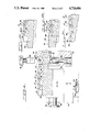
- FIG. 3 is a plan view of a pair of shearing systems used for automatic removal of the handling wires.
- FIG. 4 is a partial cross-section view of the stations of FIG. 3 along the section lines indicated in FIG. 3, with certain rear details of FIG. 3 omitted.
- FIGS. 5A-5C are detail views of a portion of FIG. 4 showing how coupled reciprocating motion of a fuse body carrier advances the fuses through the system shown in FIG. 3.
- FIG. 6A is a partial cutaway view of the lead shearing system shown in FIG. 3 along the cut lines indicated therein.
- FIGS. 6B-6C are detail views of one of the shearing blades shown in FIG. 6A.
- FIG. 7 is a detail view of a portion of FIG. 4 showing the shearing action of a shearing piston forcing an emplaced fuse downward against a spring-loaded shearing cradle to remove the leads.
- FIG. 2 shows the first step of a method whereby the subminiature fuse of the type shown in FIG. 1 can readily be fabricated.
- the finished fuse 10 consists of a cylindrical fuse body 10' of glass or other insulating material and having disposed in an axial bore therein a fusewire 14.
- the fusewire 14 is captively secured by cup-shaped conducting end caps 16,17 having flat leadless end faces 11,12.
- body carrier 24 may take a variety of designs, and in the method described herein need merely provide reasonable aligning support to the fuse body 12 during this phase of assembly.
- the body carrier 24 would be part of a continuous conveyor system automatically conveying such fuse bodies into position for cap assembly, and thereafter to subsequent stations for final processing.
- body carrier 24 is positioned to place the fuse body 10 in axial alignment with a pair of recessed cap handlers 20,20.
- the cup-shaped end caps 16,17 having a typical diameter of 0.075 inches, are provided with centrally disposed self-supporting handling filaments 18,19, most preferably in the form of metallic wires extending from the center of the end faces 11 of the terminal end caps 16,17.
- the handling filaments 18,19 are chosen to be substantially longer than the major dimensions of their associated end caps 16,17, so that the wire-receiving bores 22 axially disposed in the recessed cap handlers 20,20 serve to align the end caps 16,17 with the axis of the fuse body 12.
- the wires are preferably of a diameter of 0.025 inches.
- the recessed cap handlers 20,20 With the recessed cap handlers 20,20 thus preloaded (by means not shown), the recessed cap handlers 20,20 are driven towards each other (by means not shown) so as to force their respectively carried end caps 16,17 into final seated position over the fuseholder body 12 to produce the general configuration shown in FIG. 1, but still having the handling filaments 18,19 attached.
- a subsequent mutual retraction of the recessed cap handlers 20,20 sufficient to disengage completely from the handling filaments 18,19 allows the body carrier 24 to be moved laterally to the next processing station, most typically a heating station where the pre-tinned solder films 28-28 inside the end caps 16,17 are momentarily melted to secure positive electrical contact to the ends 15-15 of the fusewire 14.
- the handling filaments 18,19 are subsequently removed from the end faces 11,12 of the end caps 16,17, most preferably by a shearing operation conducted immediately at the junctures therebetween.
- the recessed cap handlers 20,20 may take a great variety of forms, and need not take the form of recessed pistons having wire-accommodating axial bores as shown, but may alternatively take the form of movable jaws, V-groove carrier strips, or a great many other readily loaded structures which will be evident to those of ordinary skill in the art.
- FIGS. 3-7 show a shearing system designed for automatic removal of the handling filaments 18,19 on a mass production basis.
- Lead-bearing fuses 10'-10' are sequentially loaded onto a fuse carrier 30 to be advanced towards a pair of confronting shearing stations 32,34.
- the fuses 10'-10' are loaded by conventional means (not shown) so as to be laterally confined between interior confronting faces of generally planar parallel fixedly supported guide rails 36-36.
- FIG. 4 and detail FIGS. 5A-5C show details of the system whereby the fuses are advanced towards and past the shearing stations 32,34.
- each of the guide rails 36,36 Parallel to and immediately inboard of each of the guide rails 36,36 are a pair of fixedly supported generally planar end support rails 38,38 configured with a number of V-grooves 40 in the top edges thereof.
- These support rail V-grooves 40 support the fuses 10' by engagement with their end caps 16,17.
- Wire clearance notches 42-42 in the top edges of the guide rails 36,36 are positioned so that with a fuse thus supported on the end support rails 38,38 passage of the fuse leads 18,19 therethrough is accommodated.
- FIGS. 5A-5C show the detailed sequence whereby the fuses 10' are sequentially advanced along the support rails 38-38 to the shearing stations 32,34.
- the fuse carrier 30 is generally bar-shaped, having V-grooves 44-44 at the carrier upper surface and disposed along the length thereof, the carrier being affixed to a translation table 46 mounted on ways 48,48.
- This table in turn is reciprocally movable in an advancing and a retracting direction, i.e., left and right as seen in FIG. 4, by means of a bidirectionally actuatable translation piston 50 governed by conventional drive and timing means (not shown).
- the translation table 46 is in turn slidably mounted on a lifting table 52 mounted on vertically oriented ways 54,54 and similarly actuated by a cyclically actuated lifting piston 56 so as to be raised and lowered at controlled intervals.
- the fuse advancing operation is initiated with the fuse carrier 30 in its lowermost leftward position as shown in FIG. 5A.
- the lift piston 56 is then energized to raise the fuse carrier 30, thereby raising the fuses 10'-10' to a point where their end wires 18,19 are above the tops of the end support rails 38-38 (FIG. 5B).
- the translation piston 50 is actuated to move the fuse carrier 30 forward, i.e., to the right in FIGS. 4, 5A-5C, to position each fuse 10' immediately above the next sequential pair of support V-grooves 40-40 in the support rails 38-38 (FIG. 5C).
- Dropping the lifting table 52 then causes each fuse 10'-10' to settle into engagement with, and to be supported by, the support rail V-grooves 40-40 at the next position therealong.
- the carrier 30 at this point is as shown in FIG. 4.
- the fuses are thus transported to be sequentially deposited upon the V-shaped jaws 60,60 of support rails 62,62 extending upwards from a joining yoke 64 to form a shearing cradle 66.
- the shearing cradle 66 is shown in FIG. 6A. It will be noted that the fuse carrier 30 is fully movable within and between the support rails 62 of the shearing cradle 66.
- the left shearing station 34 includes a vertically extending left shearing blade 68 affixed to the frame 70 of the system, the shearing blade having a lead accommodation groove 72 passing therethrough and through which the fusewire 19 extends.
- the left shearing blade 68 is preferably configured with a planar interior abutment face 74 facing the left end cap 12 of the emplaced fuse.
- This interior abutment face 74 is aligned (FIG. 3) in prolongation of the interior face of its adjoining guide rail 36 so that during transfer of the fuse to its shearing position leftward lateral restriction of fuse travel is maintained.
- the right shearing station 32 is provided with a right shearing blade 76 similarly configured, but mounted on a backing member 78, the backing member 78 being slidably mounted on ways 80,80 mounted on a positioning table 84 so that the right shearing blade can be withdrawn to the right or moved to the left by actuation of a positioning piston 82.
- FIG. 3 the right shearing blade 76 is shown in the extended position; however, during the loading operation of the shearing station the blade 76 is withdrawn so that the abutment face 86 thereof lies in general prolongation with its associated guide rail 36.
- Each shearing blade 68,76 is generally configured as a generally upstanding rectangular block having a downwardly and outwardly extending groove machined therein.
- the resulting structure has a sharp cutting apex 98 (see also FIGS. 6B, 6C for details) having a lead accommodation groove 72 formed therein, the planar abutment interior faces 74 thus having planar extension portions 100,100 on either side of the sharp apex 98.
- the positioning piston 82 is energized to drive the right shearing blade 76 to the left, thereby compressing the fuse 10' between the interior abutment faces 74,86 of the left shearing blade 68 and the right shearing blade 76 respectively.
- a shearing piston 88 (FIGS. 4, 6A, 7) reciprocally powered by an actuator 90 is driven downward to contact the fuse end caps 16,17, thereby forcing the fuse 10' and the shearing cradle 66 downward against the force of a shearing cradle spring 92.
- Guidance to the shearing cradle during this process is provided by an attached guiding piston 94 slidingly affixed to the positioning piston support table 84.
- the fuse end leads 18,19 are thus forced across the sharp apexes 98,98 of the shearing blades 68,76, causing the end leads to be cleanly removed (FIG. 7). The result is an almost completely burr-free removal of the handling wires 18,19.
- shearing piston 88 After shearing, the shearing piston 88 is withdrawn upward to the position shown in FIG. 4, and the shearing cradle 66 rises to the limiting position shown.
- a subsequent actuation of the carrier 30 through an advancing cycle lifts the fuse 10' out of the shearing cradle 66 to be advanced and deposited onto a dispensing chute defined by generally confronting chute walls 104,104 for delivery to the next manufacturing station.
- the handling leads which make practicable the emplacement of subminiature end caps on the fuse body by procedures adaptable to automatic assembly stations may similarly be cleanly removed by a pair of shearing stations as described above to produce a combined manufacturing process which may be completely automated.
- the present system maintains the shear blades in a stationary position, which allows the fuse to be located tightly against the blades.
- the stationary shear blade is thus used as a locator, and both blades are always flush to the cutting surface. By maintaining the blades flush to the cutting surfaces, the cut-off burr is cleanly eliminated regardless of overall part length.
Abstract
Description
Claims (17)
Priority Applications (2)
| Application Number | Priority Date | Filing Date | Title |
|---|---|---|---|
| US06/941,050 US4724606A (en) | 1986-12-19 | 1986-12-19 | Method and apparatus for making a subminiature fuse |
| JP62321156A JPS63168930A (en) | 1986-12-19 | 1987-12-18 | Method and apparatus for manufacturing supermini fuse |
Applications Claiming Priority (1)
| Application Number | Priority Date | Filing Date | Title |
|---|---|---|---|
| US06/941,050 US4724606A (en) | 1986-12-19 | 1986-12-19 | Method and apparatus for making a subminiature fuse |
Publications (1)
| Publication Number | Publication Date |
|---|---|
| US4724606A true US4724606A (en) | 1988-02-16 |
Family
ID=25475849
Family Applications (1)
| Application Number | Title | Priority Date | Filing Date |
|---|---|---|---|
| US06/941,050 Expired - Fee Related US4724606A (en) | 1986-12-19 | 1986-12-19 | Method and apparatus for making a subminiature fuse |
Country Status (2)
| Country | Link |
|---|---|
| US (1) | US4724606A (en) |
| JP (1) | JPS63168930A (en) |
Cited By (5)
| Publication number | Priority date | Publication date | Assignee | Title |
|---|---|---|---|---|
| CN1034892C (en) * | 1994-10-28 | 1997-05-14 | 佘秀月 | Fuse assembler |
| US20080007386A1 (en) * | 2006-07-05 | 2008-01-10 | K.S. Terminals, Inc. | Fuse cap for a blade fuse |
| US7479866B2 (en) | 2004-03-05 | 2009-01-20 | Littelfuse, Inc. | Low profile automotive fuse |
| US20090179727A1 (en) * | 2008-01-14 | 2009-07-16 | Littelfuse, Inc. | Blade fuse |
| CN112549405A (en) * | 2020-11-12 | 2021-03-26 | 封满秀 | Nondestructive composite resin manhole cover secondary processing device |
Citations (6)
| Publication number | Priority date | Publication date | Assignee | Title |
|---|---|---|---|---|
| US2046669A (en) * | 1932-02-20 | 1936-07-07 | Chase Shawmut Co | Electric fuse and assembling apparatus and method therefor |
| SU47909A1 (en) * | 1934-08-27 | 1936-07-31 | М.П. Меланин | Chain wheel |
| US2592019A (en) * | 1947-10-30 | 1952-04-08 | Rca Corp | Wire-cutting machine |
| US2929289A (en) * | 1955-03-25 | 1960-03-22 | Walter J Gorecki | Wire cutting apparatus comprising a rotary wire carrier movable past a fixed cutter |
| US3414959A (en) * | 1966-06-06 | 1968-12-10 | Halm Instrument Co | Capping means using vacuum |
| US3636806A (en) * | 1970-03-02 | 1972-01-25 | Dart Ind Inc | Multiple acting cutter with adjustable features |
-
1986
- 1986-12-19 US US06/941,050 patent/US4724606A/en not_active Expired - Fee Related
-
1987
- 1987-12-18 JP JP62321156A patent/JPS63168930A/en active Pending
Patent Citations (6)
| Publication number | Priority date | Publication date | Assignee | Title |
|---|---|---|---|---|
| US2046669A (en) * | 1932-02-20 | 1936-07-07 | Chase Shawmut Co | Electric fuse and assembling apparatus and method therefor |
| SU47909A1 (en) * | 1934-08-27 | 1936-07-31 | М.П. Меланин | Chain wheel |
| US2592019A (en) * | 1947-10-30 | 1952-04-08 | Rca Corp | Wire-cutting machine |
| US2929289A (en) * | 1955-03-25 | 1960-03-22 | Walter J Gorecki | Wire cutting apparatus comprising a rotary wire carrier movable past a fixed cutter |
| US3414959A (en) * | 1966-06-06 | 1968-12-10 | Halm Instrument Co | Capping means using vacuum |
| US3636806A (en) * | 1970-03-02 | 1972-01-25 | Dart Ind Inc | Multiple acting cutter with adjustable features |
Cited By (9)
| Publication number | Priority date | Publication date | Assignee | Title |
|---|---|---|---|---|
| CN1034892C (en) * | 1994-10-28 | 1997-05-14 | 佘秀月 | Fuse assembler |
| US7479866B2 (en) | 2004-03-05 | 2009-01-20 | Littelfuse, Inc. | Low profile automotive fuse |
| US20080007386A1 (en) * | 2006-07-05 | 2008-01-10 | K.S. Terminals, Inc. | Fuse cap for a blade fuse |
| US7532102B2 (en) | 2006-07-05 | 2009-05-12 | K.S. Terminals, Inc. | Fuse cap for a blade fuse |
| US20090179727A1 (en) * | 2008-01-14 | 2009-07-16 | Littelfuse, Inc. | Blade fuse |
| US7928827B2 (en) | 2008-01-14 | 2011-04-19 | Littelfuse, Inc. | Blade fuse |
| US8077007B2 (en) | 2008-01-14 | 2011-12-13 | Littlelfuse, Inc. | Blade fuse |
| CN112549405A (en) * | 2020-11-12 | 2021-03-26 | 封满秀 | Nondestructive composite resin manhole cover secondary processing device |
| CN112549405B (en) * | 2020-11-12 | 2022-10-25 | 池州市城北建筑安装有限公司 | Non-destructive secondary processing device for composite resin well lid |
Also Published As
| Publication number | Publication date |
|---|---|
| JPS63168930A (en) | 1988-07-12 |
Similar Documents
| Publication | Publication Date | Title |
|---|---|---|
| KR101822954B1 (en) | Terminal connection band, method for producing crimped terminal, wire crimping device, and wire crimping method | |
| US4663815A (en) | A method and apparatus for surface mount compatible connector system with mechanical integrity | |
| US4724606A (en) | Method and apparatus for making a subminiature fuse | |
| US4177554A (en) | Assembling leads to a substrate | |
| CA1052843A (en) | Electrical contacts | |
| KR0148254B1 (en) | Solder containing electrical connector and method for making the same | |
| US4365398A (en) | Method of and apparatus for assembling intermediate-web held terminal pins | |
| EP0303873A2 (en) | Conductive lead arrangement | |
| US4503609A (en) | Low-insertion force method of assembling a lead and a substrate | |
| CA1209796A (en) | Method of, and apparatus for, terminating an electrical conductor to an electrical connector | |
| US4293890A (en) | Ceramic capacitor with end terminals | |
| US6261136B1 (en) | Edge clip terminal | |
| JP2852527B2 (en) | Method and apparatus for manufacturing wire harness | |
| US4482197A (en) | Low-insertion force solder-bearing lead | |
| US4785988A (en) | Attachment of lead to elongated conductor | |
| US4502745A (en) | Progressively-increasing clamping force lead and lead-substrate assembly | |
| CN112845963A (en) | Component shaping and cutting device | |
| US4773157A (en) | Method of making an electrical termination | |
| EP0281244A2 (en) | Pitch transition wire guide apparatus for fabricating electrical harnesses | |
| US4494033A (en) | Thin lead suspension for a piezoelectric resonator | |
| EP0079161A2 (en) | LED lamp and mounting base therefor | |
| US4639988A (en) | Method of making quartz oscillators | |
| US3943625A (en) | Method for making tined electrical contacts | |
| CA2069913C (en) | Device for producing a contact device, contact device and the use thereof | |
| CA1295112C (en) | Method and apparatus for assembling electrical connectors |
Legal Events
| Date | Code | Title | Description |
|---|---|---|---|
| AS | Assignment |
Owner name: LITTELFUSE, INC., A CORP. OF ILL. Free format text: ASSIGNMENT OF ASSIGNORS INTEREST.;ASSIGNOR:SEXTON, WILLIAM F. JR.;REEL/FRAME:004772/0523 Effective date: 19861212 Owner name: LITTELFUSE, INC., L. Free format text: ASSIGNMENT OF ASSIGNORS INTEREST;ASSIGNOR:SEXTON, WILLIAM F. JR.;REEL/FRAME:004772/0523 Effective date: 19861212 |
|
| AS | Assignment |
Owner name: BANK OF AMERICA NATIONAL TRUST AND SAVINGS ASSOCIA Free format text: SECURITY INTEREST;ASSIGNOR:TRACOR HOLDINGS, INC., TRACOR, INC., AND OTHERS INDICATED ON SCHEDULE SA;REEL/FRAME:005317/0726 Effective date: 19891030 |
|
| REMI | Maintenance fee reminder mailed | ||
| AS | Assignment |
Owner name: TORONTO-DOMINION BANK TRUST COMPANY, THE Free format text: SECURITY INTEREST;ASSIGNOR:LITTELFUSE, INC.;REEL/FRAME:005955/0282 Effective date: 19911227 Owner name: OTC LITTELFUSE, INC. Free format text: CHANGE OF NAME;ASSIGNOR:LITTELFUSE, INC.;REEL/FRAME:005955/0337 Effective date: 19911122 Owner name: LITTELFUSE, INC. Free format text: ASSIGNMENT OF ASSIGNORS INTEREST.;ASSIGNOR:OTC LITTLEFUSE, INC. AN ILLINOIS CORPORATION;REEL/FRAME:005947/0777 Effective date: 19911220 Owner name: TRACOR, INC. Free format text: RELEASED BY SECURED PARTY;ASSIGNOR:BANK OF AMERICA NATIONAL TRUST AND SAVINGS ASSOCIATION;REEL/FRAME:005953/0942 Effective date: 19911227 |
|
| LAPS | Lapse for failure to pay maintenance fees | ||
| FP | Lapsed due to failure to pay maintenance fee |
Effective date: 19920216 |
|
| AS | Assignment |
Owner name: LITTELFUSE, INC., ILLINOIS Free format text: RELEASE OF SECURITY INTEREST AGREEMENT;ASSIGNOR:TORONTO-DOMINION BANK TRUST COMPANY;REEL/FRAME:006677/0653 Effective date: 19930831 |
|
| STCH | Information on status: patent discontinuation |
Free format text: PATENT EXPIRED DUE TO NONPAYMENT OF MAINTENANCE FEES UNDER 37 CFR 1.362 |