US4729029A - Process and apparatus for the insertion of insets into the image supplied by a digital scan converter - Google Patents

Process and apparatus for the insertion of insets into the image supplied by a digital scan converter Download PDF

Info

Publication number
US4729029A
US4729029A US06/845,317 US84531786A US4729029A US 4729029 A US4729029 A US 4729029A US 84531786 A US84531786 A US 84531786A US 4729029 A US4729029 A US 4729029A
Authority
US
United States
Prior art keywords
image
inset
basic
generating
video information
Prior art date
Legal status (The legal status is an assumption and is not a legal conclusion. Google has not performed a legal analysis and makes no representation as to the accuracy of the status listed.)
Expired - Fee Related
Application number
US06/845,317
Inventor
Jean C. Henri
Jean P. Andrieu
Current Assignee (The listed assignees may be inaccurate. Google has not performed a legal analysis and makes no representation or warranty as to the accuracy of the list.)
Thales SA
Original Assignee
Thomson CSF SA
Priority date (The priority date is an assumption and is not a legal conclusion. Google has not performed a legal analysis and makes no representation as to the accuracy of the date listed.)
Filing date
Publication date
Application filed by Thomson CSF SA filed Critical Thomson CSF SA
Assigned to THOMSON-CSF reassignment THOMSON-CSF ASSIGNMENT OF ASSIGNORS INTEREST. Assignors: ANDRIEU, JEAN P., HENRI, JEAN CLAUDE
Application granted granted Critical
Publication of US4729029A publication Critical patent/US4729029A/en
Anticipated expiration legal-status Critical
Expired - Fee Related legal-status Critical Current

Links

Images

Classifications

    • GPHYSICS
    • G01MEASURING; TESTING
    • G01SRADIO DIRECTION-FINDING; RADIO NAVIGATION; DETERMINING DISTANCE OR VELOCITY BY USE OF RADIO WAVES; LOCATING OR PRESENCE-DETECTING BY USE OF THE REFLECTION OR RERADIATION OF RADIO WAVES; ANALOGOUS ARRANGEMENTS USING OTHER WAVES
    • G01S7/00Details of systems according to groups G01S13/00, G01S15/00, G01S17/00
    • G01S7/02Details of systems according to groups G01S13/00, G01S15/00, G01S17/00 of systems according to group G01S13/00
    • G01S7/28Details of pulse systems
    • G01S7/285Receivers
    • G01S7/295Means for transforming co-ordinates or for evaluating data, e.g. using computers
    • G01S7/298Scan converters

Definitions

  • the present invention relates to a digital image scan converter or D.I.C. It more specifically relates to a process for the insertion of magnified insets into the image supplied by such a D.I.C., as well as to the D.I.C. for performing this process.
  • the essential function of a D.I.C. is to convert an image supplied in polar coordinates and which is relatively slowly renewable into a bright television-type image or picture, thereby permitting its exploitation in an illuminated ambient.
  • This slowly renewable image is generally a radar image, but it can also be an image from a sonar, an infrared sensor, an echo sounding system or the like, which can be displayed on a screen operating in the television mode.
  • FIG. 1 shows the block diagram of a D.I.C. in the case of a radar.
  • the D.I.C. comprises the following components:
  • the capacity of memory 4 is adapted to the television standard used, i.e. it must have the same number of storage positions as the image displayed on the television monitor has points (or pixels).
  • the brightness of each point is coded by means of a certain number of bits, e.g. three bits authorizing eight brightness levels for each point.
  • the reading phase of the content of memory 4 intended for the television monitor 7 and the phase of writing into the memory the radar information supplied by an assembly 2 are asynchronous. Reading has priority and writing is stopped during a reading phase.
  • An assembly 1 of circuits is provided for processing the radar video signals received by the D.I.C. It is pointed out that analog video signals are constituted on the one hand by a sync signal (S Y ) indicating that a pulse has been emitted by the radar, and on the other hand by the actual video ( ⁇ ), constituted by all the responses (echos) to said pulse. Assembly 1 in particular ensures the conversion of the incident analog video signal into digital form signal, the processing of said signal, whose details are variable as a function of the radar type, and the storage of the video information corresponding to each radar pulse, called radial sweep.
  • assembly 3 receives the signals representing the rotation of the radar antenna, i.e. indicating at all times the angular position of the beam of the radar (radar antenna) with respect to a reference direction, generally North.
  • the rotation signals are on the one hand constituted by a north signal (N), which is a pulse signal supplied during each passage of the beam through North and on the other hand by an angle increment signal ( ⁇ ) indicating that the beam has turned by an nth of a turn with respect to the preceding increment, if n increments correspond to 360°.
  • N north signal
  • angle increment signal
  • An assembly 5 of television mode reading circuits ensures the read addressing of the image memory 4.
  • An assembly 6 of television mode output circuits receives the information stored in the image memory 4 and as addressed by assembly 5, ensures the digital-analog conversion to produce the television video signal intended for monitor 7, as well as the generation of conventional television sync signals.
  • An assembly 2 of artificial persistence or afterglow circuits whose function is to produce for the digital information stored in memory 4 for which there is no modification due to aging, a persistence effect comparable to that produced on a tube where the brightness of a point starts to decrease as soon as it is written.
  • An assembly 8 of control circuits e.g. realized by means of a microprocessor, receives both the radar video signals and the rotation signals and ensures the control and synchronization of all the aforementioned assemblies, apart from the monitor 7.
  • the image memory 4 contains the image as it will be displayed on the television monitor 7, this image then being called the basic image.
  • FIGS. 2a and 2b show an example of the display of an area monitored by a radar.
  • a circle indicates the range P of a radar located at a point C o , forming the center of the circle P.
  • the displayed part in FIG. 2b shows an airport having runways and taxiways along which are travelling two aircraft A 1 and A 2 .
  • insets M 2 and M 3 which are preferably inserted in those parts of the basic image I not useful to the operator.
  • the surface of the magnified parts and their magnification are not necessarily the same for each inset.
  • an inset M 1 is inserted in image I from part of the area P covered by the radar not included in the displayed portion I.
  • the surface and magnification coefficient of said inset M 1 are also of a random nature compared with those of other insets.
  • An object of the present invention is a process which produces the inset during the writing of the video information into the image memory, which makes it possible to increase the definition of the inset.
  • the image memory then contains both the basic image and the insets, the latter being stored with the desired coordinates (Cartesian coordinates) and magnification.
  • the Cartesian coordinates of the points of each inset are obtained by modifying data used for the conversion of coordinates of the basic image by the conversion assembly 3.
  • the desired magnification is obtained by corresponding modification of the sampling period of the analog video information during its conversion into digital form by assembly 1, which makes it possible to increase the definition of the inset compared with the basic image.
  • FIG. 1 already described, the block diagram of a D.I.C.
  • FIGS. 2a and 2b already described, an example of a basic image having insets which can be displayed by a D.I.C.
  • FIG. 3 an embodiment of part of FIG. 1.
  • FIGS. 4 and 5 two diagrams explaining the conversion of the coordinates used for the insets.
  • FIG. 6 an embodiment of another part of FIG. 1.
  • FIG. 1 shows a conventional image converter.
  • the dotted leads 101, 102, 103 as well as the elements 1 and 3 are descriptive of the present invention.
  • FIG. 3 shows an embodiment of the radar video signal processing group 1. It comprises a circuit 21 (i.e., sampling circuit) for sampling the analog video signal received from the radar, which supplies said video in digital form to an assembly of circuits 22 (i.e., mixing dosing circuit).
  • a circuit 21 i.e., sampling circuit
  • circuits 22 i.e., mixing dosing circuit
  • an assembly such as 1 can receive several video signals from a radar.
  • Assembly 22 also receives digital video signals from the same radar (e.g. cartography data, see the legend "Digital Radar Videos” in FIG. 3) and ensures the mixing and dosing of all these information, which it then transmits to a so-called radial memory 23, which thus contains the processed, digitized video signal relative to a radar pulse.
  • assembly 1 can contain several alternately functioning radial memories. Circuits 21, 22 and 23 (i.e., sampling circuit 21, mixing dosing 22 and radial memory 23) function under the action of a processing control circuit 24, which is itself related to the control assembly 8 (FIG. 1).
  • image memory 4 stores both the basic image and the desired insets with the desired magnification. For this purpose, two variants are provided.
  • the processing assembly 1 comprises at least one radial memory for the radar pulses of the basic image and one radial memory for each of the insets to be produced (not shown in FIG. 3).
  • the total number of insets possible in an image is accordingly defined by the number of radial memories allocated to the insets in the system.
  • the radial memory of the basic image contains the digitized video signal processed in a conventional manner.
  • the radial memory of each inset contains that part of the video signal related to the inset and sampled so as to be stored at a frequency higher than that of the basic image and corresponds to the desired magnification, e.g. double the frequency for a magnification of 2.
  • assembly 1 only contains a single radial memory in which the video information is stored with the maximum available definition in the system. If K is the maximum desired magnification for an inset, the data for forming the basic image will be picked up in one storage position per group of K radial storage positions (1/K).
  • the information will be picked up k times on K positions (k ⁇ 1/K), with 1 ⁇ k ⁇ K.
  • the sampling frequency (circuit 21) and the definition of the basic image consequently fix the maximum possible magnification K for the insets.
  • the coordinate conversion assembly 3 (FIG. 1) has to carry out a conventional conversion for the basic image and also a specific conversion for each of the insets.
  • FIG. 4 shows an image I, such as is stored in the image memory and as will appear on the television monitor.
  • the center C o of the radar (of Cartesian coordinates x o and y o ) does not coincide with the center O of the displayed image I.
  • the area to be magnified is designated M 4 and its center C F has the Cartesian coordinates x F and y F .
  • Line C o C F forms an angle ⁇ with axis Oy.
  • This area M 4 will form an inset M 5 , where the coordinates of center C M are respectively x M and y M .
  • the magnification coefficient of inset M 5 and C 1 , of coordinates x 1 and y 1 the position which will be occupied by the center of the radar C o for inset M 5 is: ##EQU1##
  • FIG. 5 is a diagram identical to that of FIG. 4, except the area at which an inset is to be formed also undergoes rotation by a given angle ⁇ '.
  • FIG. 5 has the following modifications.
  • Area M 6 from which an inset is to be made has, for example, the same center C F and the same dimensions (e.g. a square) as area M 4 in FIG. 4, but its axis of symmetry passing through the center of the sides forms an angle ⁇ ' with axis Oy. It is desired to subject it to a rotation ⁇ ' in order to bring the aforementioned axis parallel to axis Oy.
  • This area which has undergone a rotation ⁇ ' is shown dotted in FIG. 5 and designated M 7 .
  • the inset corresponding to area M 6 /M 7 is designated M 8 and has as its center point C M , as hereinbefore.
  • C 2 designates the position of center C o relative to inset M 8 . Coordinates x 2 and y 2 of point C 2 are given by the following formulas: ##EQU2##
  • FIG. 6 shows an embodiment of the coordinate conversion assembly 3 of FIG. 1.
  • FIG. 6 also shows the control assembly 8, which receives the information concerning the desired inset or insets from the operator.
  • the coordinate conversion assembly 3 comprises the following parts:
  • a table 10 of the different values of the trigonometric functions e.g. the sine and cosine of each of the angles ⁇ i (i varying from 1 to n) respectively defining the n radar pulses, said table being constituted by a memory, addressed by the angle increments ⁇ , for example, and reset by the N signal.
  • An accumulator 12 receiving from the aforementioned table 10 the value sin ⁇ i and from the control assembly 8 the coordinate x o of the center C o for the basic image, x 1 or x 2 for the centers C 1 or C 2 of an inset.
  • Accumulator 12 comprises an adder 22 surrounded by an input register 21, which receives for each radial sweep the value of sin ⁇ i , as well as an output register 23, which receives the initial coordinate of the radar input (x o , x 1 or x 2 ).
  • the output of the register 23 on the one hand supplies the current coordinate x j along the radial sweep during the accumulations and on the other hand is also directed towards the adder 22.
  • Accumulation is initiated by the conversion control assembly 11.
  • An accumulator 13, idential to accumulator 12, i.e. comprising an adder 25 surrounded by an input register 24 and an output register 26, performs an accumulation in cosine and supplies the Cartesian coordinate y j y j-1 +cos ⁇ i .
  • a writing addressing device 14 selects an address in image memory 4 where the video information is to be written.
  • conversion assembly 3 also comprises a buffer memory 15, positioned between the radial memory 23 (of processing assembly 1) and the persistence assembly 2.
  • the conversion control circuit 11 controls in a first step the reading of the radial memory 23 (with the appropriate definition) and the writing of said information into the buffer 15 via conductor 101.
  • the circuit 11 controls the reading of the buffer 15 over conductor 102 intended for the image memory 4 (via the assembly 2) synchronously with the writing addressing of said memory 4.
  • the operation of the device of FIG. 6 takes place in two steps for each radial sweep, being characterized by an angle ⁇ i (1 ⁇ i ⁇ n).
  • accumulators 12 and 13 supply the current coordinates x j and y j of a radial sweep (from the position of radar C o to the periphery of the TV display) for the basic image, from corrdinates x o and y o supplied by the control assembly 8.
  • the video information relating to the basic image and stored in the radial memory 23 (FIG. 3) or in the buffer 15 (FIG. 6) is written into the image memory 4 at addresses x j , y j .
  • video data is transferred at the rate of 1/K.
  • the persistence mechanism assembly 2 FIG.
  • the writing of the basic image into image memory 4 is inhibited in the area (M 5 , M 8 ) of image I where the inset is to be written in.
  • This may be brought about by inhibiting the transfer of the video relative to the basic image into the image memory, i.e. there is no reading at that time of the content of the radial memory or the buffer store under the control of assemblies 8 or 11, the conversion of the coordinates being continued normally during this time.
  • This may be also brought about by the non-operation of the accumulators in the area M 5 or M 8 in question, under the control of circuits 8 and 11. In this latter case, it is then necessary to reinitialize the accumulators (registers 23a and 26) at the output of areas M 5 and M 8 .
  • accumulators 12, 13 supply the current coordinates x j and y j for the inset, from the coordinates x 1 and y 1 (or x 2 and y 2 ) supplied by the control assembly 8.
  • the content of the radial memory (or the buffer) relating to the inset is written into the image memory at addresses x j and y j .
  • video data is transferred at the higher rate k/K.
  • writing of information relative to the inset only takes place for the coordinates corresponding to areas M 5 or M 8 .
  • control assembly 8 ensures the switching between the different assemblies respectively working on the basic image and on the insets. In this embodiment, it is simpler to provide a buffer 15 in each assembly 3.
  • the image memory 4 contains the basic image into which the inset are directly inserted.
  • One advantage of this solution is a memory space economy. Its disadvantage is that is requires an inhibition of the writing of the basic image, the image memory 4 with regard to the areas where an inset is to be formed.
  • the image memory 4 contains both the complete basic image and the inset or insets in supplementary memory spaces. It should be noted that the writing into the image memory here again takes place by one or more conversion assembly 3. The display on monitor 7 of an image in which the insets are inserted at the desired location is then carried out by the reading assembly 5, under the control of assembly 8, assembly 5 ensuring the reading of the appropriate information by the control of the reading addresses of the image memory.

Abstract

In a digital scan converter particularly for radar images, a process produces a magnified inset during the writing of the video information into the image memory. This makes it possible to increase the definition of the inset. The image memory then contains both the basic image and the insets, the latter being stored with the desired Cartesian coordinates and magnification. The Cartesian coordinates of the points of each inset are obtained by modifying data used for converting the basic image coordinates by the conversion circuits. The desired magnification is obtained by the corresponding modification of the sampling period of the analog video information during its conversion into digital form by the video processing circuits, which makes it possible to increase the definition of the inset compared with that of the basic image.

Description

BACKGROUND OF THE INVENTION
The present invention relates to a digital image scan converter or D.I.C. It more specifically relates to a process for the insertion of magnified insets into the image supplied by such a D.I.C., as well as to the D.I.C. for performing this process.
The essential function of a D.I.C. is to convert an image supplied in polar coordinates and which is relatively slowly renewable into a bright television-type image or picture, thereby permitting its exploitation in an illuminated ambient. This slowly renewable image is generally a radar image, but it can also be an image from a sonar, an infrared sensor, an echo sounding system or the like, which can be displayed on a screen operating in the television mode.
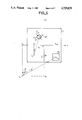
FIG. 1 shows the block diagram of a D.I.C. in the case of a radar. The D.I.C. comprises the following components:
A television monitor 7 on which the radar information is displayed.
An image memory 4 containing in digital form the image to be displayed on the monitor 7. The capacity of memory 4 is adapted to the television standard used, i.e. it must have the same number of storage positions as the image displayed on the television monitor has points (or pixels). In addition, the brightness of each point is coded by means of a certain number of bits, e.g. three bits authorizing eight brightness levels for each point. The reading phase of the content of memory 4 intended for the television monitor 7 and the phase of writing into the memory the radar information supplied by an assembly 2 are asynchronous. Reading has priority and writing is stopped during a reading phase.
An assembly 1 of circuits is provided for processing the radar video signals received by the D.I.C. It is pointed out that analog video signals are constituted on the one hand by a sync signal (SY) indicating that a pulse has been emitted by the radar, and on the other hand by the actual video (ρ), constituted by all the responses (echos) to said pulse. Assembly 1 in particular ensures the conversion of the incident analog video signal into digital form signal, the processing of said signal, whose details are variable as a function of the radar type, and the storage of the video information corresponding to each radar pulse, called radial sweep.
An assembly 3 of coordinate conversion circuits is needed because the radar information, which is generally supplied in polar coordinates, has to be written onto the television screen 7 in Cartesian coordinates. For this purpose, assembly 3 receives the signals representing the rotation of the radar antenna, i.e. indicating at all times the angular position of the beam of the radar (radar antenna) with respect to a reference direction, generally North. The rotation signals are on the one hand constituted by a north signal (N), which is a pulse signal supplied during each passage of the beam through North and on the other hand by an angle increment signal (ε) indicating that the beam has turned by an nth of a turn with respect to the preceding increment, if n increments correspond to 360°. Thus, assembly 3 ensures the addressing of the image memory 4, whereby the processing assembly 1 supplies via an assembly 2, the information to be written into the image memory 4, synchronously with the addressing.
An assembly 5 of television mode reading circuits ensures the read addressing of the image memory 4.
An assembly 6 of television mode output circuits receives the information stored in the image memory 4 and as addressed by assembly 5, ensures the digital-analog conversion to produce the television video signal intended for monitor 7, as well as the generation of conventional television sync signals.
An assembly 2 of artificial persistence or afterglow circuits, whose function is to produce for the digital information stored in memory 4 for which there is no modification due to aging, a persistence effect comparable to that produced on a tube where the brightness of a point starts to decrease as soon as it is written.
An assembly 8 of control circuits, e.g. realized by means of a microprocessor, receives both the radar video signals and the rotation signals and ensures the control and synchronization of all the aforementioned assemblies, apart from the monitor 7.
Thus, after converting the scanning standard (polar into Cartesian), the image memory 4 contains the image as it will be displayed on the television monitor 7, this image then being called the basic image.
The problem which is often encountered by the operator is that of wishing to magnify one or more areas of said basic image, where an important detail requires examination. These magnified areas are called "insets".
FIGS. 2a and 2b show an example of the display of an area monitored by a radar. In FIG. 2a, a circle indicates the range P of a radar located at a point Co, forming the center of the circle P. Of the area P covered by the radar, only a part is displayed in the form of an image I as shown in FIG. 2b. For example, the displayed part in FIG. 2b shows an airport having runways and taxiways along which are travelling two aircraft A1 and A2.
In exemplified manner, it is possible to magnify those areas of the basic image I surrounding aircraft A1 and A2 to respectively form insets M2 and M3 which are preferably inserted in those parts of the basic image I not useful to the operator. It should be noted that the surface of the magnified parts and their magnification are not necessarily the same for each inset. Moreover, still in exemplified manner, an inset M1 is inserted in image I from part of the area P covered by the radar not included in the displayed portion I. The surface and magnification coefficient of said inset M1 are also of a random nature compared with those of other insets.
It is known to obtain such a partial magnification by expansion, during the reading of the image memory, of an area of the image supplied by the memory, each of the points intended to be part of the inset then being repeated identically thereto k times, if k is the sought magnification coefficient. This method is known as "zoom". It has the drawback of not improving the definition of the observed magnified area and consequently the overall definition of the inset is very inferior to that of the remainder of the basic image.
SUMMARY OF THE INVENTION
An object of the present invention is a process which produces the inset during the writing of the video information into the image memory, which makes it possible to increase the definition of the inset. The image memory then contains both the basic image and the insets, the latter being stored with the desired coordinates (Cartesian coordinates) and magnification. The Cartesian coordinates of the points of each inset are obtained by modifying data used for the conversion of coordinates of the basic image by the conversion assembly 3. The desired magnification is obtained by corresponding modification of the sampling period of the analog video information during its conversion into digital form by assembly 1, which makes it possible to increase the definition of the inset compared with the basic image.
BRIEF DESCRIPTION OF THE DRAWINGS
The invention is described in greater detail hereinafter relative to non-limitative embodiments and the attached drawings, wherein there is shown:
FIG. 1, already described, the block diagram of a D.I.C.
FIGS. 2a and 2b already described, an example of a basic image having insets which can be displayed by a D.I.C.
FIG. 3, an embodiment of part of FIG. 1.
FIGS. 4 and 5, two diagrams explaining the conversion of the coordinates used for the insets.
FIG. 6, an embodiment of another part of FIG. 1.
In the various drawings, the same references relate to the same elements.
DETAILED DESCRIPTION OF THE PREFERRED EMBODIMENTS
As will be described hereafter, FIG. 1, in full lines, shows a conventional image converter. The dotted leads 101, 102, 103 as well as the elements 1 and 3 (shown in more detail in FIGS. 3 and 6) are descriptive of the present invention.
FIG. 3 shows an embodiment of the radar video signal processing group 1. It comprises a circuit 21 (i.e., sampling circuit) for sampling the analog video signal received from the radar, which supplies said video in digital form to an assembly of circuits 22 (i.e., mixing dosing circuit).
It should be noted that an assembly such as 1 can receive several video signals from a radar. Assembly 22 also receives digital video signals from the same radar (e.g. cartography data, see the legend "Digital Radar Videos" in FIG. 3) and ensures the mixing and dosing of all these information, which it then transmits to a so-called radial memory 23, which thus contains the processed, digitized video signal relative to a radar pulse. In a variant, assembly 1 can contain several alternately functioning radial memories. Circuits 21, 22 and 23 (i.e., sampling circuit 21, mixing dosing 22 and radial memory 23) function under the action of a processing control circuit 24, which is itself related to the control assembly 8 (FIG. 1).
According to the invention, image memory 4 stores both the basic image and the desired insets with the desired magnification. For this purpose, two variants are provided.
According to the first variant, the processing assembly 1 comprises at least one radial memory for the radar pulses of the basic image and one radial memory for each of the insets to be produced (not shown in FIG. 3). The total number of insets possible in an image is accordingly defined by the number of radial memories allocated to the insets in the system. The radial memory of the basic image contains the digitized video signal processed in a conventional manner. The radial memory of each inset contains that part of the video signal related to the inset and sampled so as to be stored at a frequency higher than that of the basic image and corresponds to the desired magnification, e.g. double the frequency for a magnification of 2.
According to the second variant, assembly 1 only contains a single radial memory in which the video information is stored with the maximum available definition in the system. If K is the maximum desired magnification for an inset, the data for forming the basic image will be picked up in one storage position per group of K radial storage positions (1/K).
For an inset of magnification k, the information will be picked up k times on K positions (k·1/K), with 1≦k·≦K.
The sampling frequency (circuit 21) and the definition of the basic image consequently fix the maximum possible magnification K for the insets.
The coordinate conversion assembly 3 (FIG. 1) has to carry out a conventional conversion for the basic image and also a specific conversion for each of the insets.
FIG. 4 shows an image I, such as is stored in the image memory and as will appear on the television monitor. For example, on said image I, the center Co of the radar (of Cartesian coordinates xo and yo) does not coincide with the center O of the displayed image I. The area to be magnified is designated M4 and its center CF has the Cartesian coordinates xF and yF. Line Co CF forms an angle θ with axis Oy. This area M4 will form an inset M5, where the coordinates of center CM are respectively xM and yM. On calling k the magnification coefficient of inset M5 and C1, of coordinates x1 and y1, the position which will be occupied by the center of the radar Co for inset M5 is: ##EQU1##
FIG. 5 is a diagram identical to that of FIG. 4, except the area at which an inset is to be formed also undergoes rotation by a given angle θ'.
Thus, compared with FIG. 4, FIG. 5 has the following modifications. Area M6 from which an inset is to be made has, for example, the same center CF and the same dimensions (e.g. a square) as area M4 in FIG. 4, but its axis of symmetry passing through the center of the sides forms an angle θ' with axis Oy. It is desired to subject it to a rotation θ' in order to bring the aforementioned axis parallel to axis Oy. This area which has undergone a rotation θ' is shown dotted in FIG. 5 and designated M7. The inset corresponding to area M6 /M7 is designated M8 and has as its center point CM, as hereinbefore. C2 designates the position of center Co relative to inset M8. Coordinates x2 and y2 of point C2 are given by the following formulas: ##EQU2##
FIG. 6 shows an embodiment of the coordinate conversion assembly 3 of FIG. 1. FIG. 6 also shows the control assembly 8, which receives the information concerning the desired inset or insets from the operator.
The coordinate conversion assembly 3 comprises the following parts:
An assembly 11 of conversion control circuits associated with the control assembly 8 and providing an output 103 to control the processing element 1.
A table 10 of the different values of the trigonometric functions, e.g. the sine and cosine of each of the angles θi (i varying from 1 to n) respectively defining the n radar pulses, said table being constituted by a memory, addressed by the angle increments ε, for example, and reset by the N signal.
An accumulator 12, receiving from the aforementioned table 10 the value sin θi and from the control assembly 8 the coordinate xo of the center Co for the basic image, x1 or x2 for the centers C1 or C2 of an inset. Accumulator 12 comprises an adder 22 surrounded by an input register 21, which receives for each radial sweep the value of sin θi, as well as an output register 23, which receives the initial coordinate of the radar input (xo, x1 or x2). The output of the register 23 on the one hand supplies the current coordinate xj along the radial sweep during the accumulations and on the other hand is also directed towards the adder 22. Accumulation is initiated by the conversion control assembly 11. The accumulator supplies the Cartesian coordinate xj =xj-1 +sin θi during each accumulation step and for the same value of θi, i.e. for the same radial sweep.
An accumulator 13, idential to accumulator 12, i.e. comprising an adder 25 surrounded by an input register 24 and an output register 26, performs an accumulation in cosine and supplies the Cartesian coordinate yj =yj-1 +cos θi.
A writing addressing device 14 selects an address in image memory 4 where the video information is to be written.
According to a variant shown in FIG. 6 conversion assembly 3 also comprises a buffer memory 15, positioned between the radial memory 23 (of processing assembly 1) and the persistence assembly 2. In this case, the conversion control circuit 11 controls in a first step the reading of the radial memory 23 (with the appropriate definition) and the writing of said information into the buffer 15 via conductor 101. In a second step, the circuit 11 controls the reading of the buffer 15 over conductor 102 intended for the image memory 4 (via the assembly 2) synchronously with the writing addressing of said memory 4.
In the case where the number of desired insets and the arrival rate of the radar information to be displayed are compatible with the accumulation speed of conversion assembly 3, a single set of accumulators is sufficient to ensure the conversions of the relative coordinates successively of the basic image and the inset or insets. In this case, according to a preferred embodiment, the operation of the device of FIG. 6 takes place in two steps for each radial sweep, being characterized by an angle θi (1≦i≦n).
In a first step, accumulators 12 and 13 supply the current coordinates xj and yj of a radial sweep (from the position of radar Co to the periphery of the TV display) for the basic image, from corrdinates xo and yo supplied by the control assembly 8. Synchronously and supervised by assembly 8, the video information relating to the basic image and stored in the radial memory 23 (FIG. 3) or in the buffer 15 (FIG. 6) is written into the image memory 4 at addresses xj, yj. During this writing step video data is transferred at the rate of 1/K. However, in order to avoid any disturbance to the persistence mechanism (assembly 2 FIG. 1), the writing of the basic image into image memory 4 is inhibited in the area (M5, M8) of image I where the inset is to be written in. This may be brought about by inhibiting the transfer of the video relative to the basic image into the image memory, i.e. there is no reading at that time of the content of the radial memory or the buffer store under the control of assemblies 8 or 11, the conversion of the coordinates being continued normally during this time. This may be also brought about by the non-operation of the accumulators in the area M5 or M8 in question, under the control of circuits 8 and 11. In this latter case, it is then necessary to reinitialize the accumulators (registers 23a and 26) at the output of areas M5 and M8.
In a second step and for the same radial sweep, accumulators 12, 13 supply the current coordinates xj and yj for the inset, from the coordinates x1 and y1 (or x2 and y2) supplied by the control assembly 8. As hereinbefore, synchronously the content of the radial memory (or the buffer) relating to the inset is written into the image memory at addresses xj and yj. During this writing step video data is transferred at the higher rate k/K. As hereinbefore and in the same way, writing of information relative to the inset only takes place for the coordinates corresponding to areas M5 or M8.
When the rate of the radar information or the number of insets increases, several assemblies such as 3 are needed, one being allocated to the basic image and the other or others to the different insets. The control assembly 8 then ensures the switching between the different assemblies respectively working on the basic image and on the insets. In this embodiment, it is simpler to provide a buffer 15 in each assembly 3.
In the embodiment described hereinbefore, the image memory 4 contains the basic image into which the inset are directly inserted. One advantage of this solution is a memory space economy. Its disadvantage is that is requires an inhibition of the writing of the basic image, the image memory 4 with regard to the areas where an inset is to be formed.
In another embodiment, the image memory 4 contains both the complete basic image and the inset or insets in supplementary memory spaces. It should be noted that the writing into the image memory here again takes place by one or more conversion assembly 3. The display on monitor 7 of an image in which the insets are inserted at the desired location is then carried out by the reading assembly 5, under the control of assembly 8, assembly 5 ensuring the reading of the appropriate information by the control of the reading addresses of the image memory.
The above description has been given in a non-limitative manner. Thus, a coordinate conversion calling on sine and cosine trigonometric functions has been described. However and as is known, said conversion can also be carried out with the tangent function, the same considerations regarding the speed and number of accumulators again applying.

Claims (16)

What is claimed is:
1. A process for insertion of an inset image portion into an image generated by a digital image converter including a television type image display, an image memory storing, in digital form, a basic image to displayed on the television type display, processing means including storage means for sampling and storing video information as the video information is supplied to the digital image converter, coordinate conversion means for generating Cartesian coordinates for the video information which is supplied to the digital image converter in accordance with polar coordinates, said process including the steps of:
sampling video information received by the digital image converter, including sampling video information for said basic image at a first frequency and sampling video information for said inset image portion at a second frequency, higher than said first frequency,
storing video information associated with an inset image portion in said storage means with a magnification factor k relative to said basic image, where k>1,
generating coordinates for an inset image portion employing parameters which are functions of a desired position for the inset image portion in the basic image and the magnification factor k for the inset image portion, and
writing said video information associated with an inset image portion from said storage means to said image memory at addresses in said image memory defined by coordinates produced in said generating step.
2. A process as recited in claim 1 wherein:
said storing step also stores video data associated with the basic image in said storage means, and wherein said basic image has a definition which is a function of a maximum magnification factor K for any inset image portion,
said writing step writes video data associated with said basic image to said image memory at a rate 1/K and wherein video data associated with said inset image portion is written to said image memory at a rate of k/K.
3. A process as recited in claim 1 wherein said generating step includes a video data rotation function for rotating video data associated with an inset image through an angle forming one of the parameters used in the generating step.
4. A process as recited in either claim 1 or 2 or 3 wherein said image memory includes a region dedicated to said basic image and a separate region dedicated to said inset image portion, said process including a further step of creating said image by reading said image memory at said region and at said separate region.
5. A process as recited in claim 1 or 2 or 3 wherein said writing said image memory with video data associated with said basic image is inhibited with respect to regions of the basic image which are to be occupied by an inset image portion.
6. A digital image converter for insertion of an inset image portion into a basic image defined by video image data supplied to said digital image converter including a television type image display, an image memory storing, in digital form, a basic image to displayed on the television type display, processing means including storage means for storing video information as the video information is supplied to the digital image converter, coordinate conversion means for generating Cartesian coordinates for the video information which is supplied to the digital image converter in accordance with polar coordinates,
said processing means including means for sampling received video information, said means for sampling, sampling video image data for a basic image at a first frequency and sampling video image data for an inset image portion at a second, higher frequency, and
means responsive to said sampling means for storing video information associated with an inset image portion in said storage means with a magnification factor k relative to said basic image, where k>1,
said coordinate conversion means including means for generating coordinates for an inset image portion employing parameters which are functions of a desired position for the inset image portion in the basic image and the magnification factor k for the inset image portion, and
said digital image converter further including means for writing said video information associated with an inset image portion to said image memory at addresses in said image memory defined by coordinates produced in said means for generating.
7. Apparatus as recited in claim 6 wherein:
said means for generating includes buffer means for storing video information associated with an inset image portion and responsive to said storage means.
8. Apparatus as recited in claim 7 wherein said coordinate conversion means and said means for generating includes:
basic generating means for generating Cartesian coordinates for said basic image, and
second generating means for generating Cartesian coordinates for an inset image portion,
said basic generating means including a basic buffer means and said second generating means including said buffer means, both said basic and buffer means each responsive to said storage means for storing respective portions of the video data stored in said storage means.
9. A process for insertion of an inset image portion into an image generated by a digital image converter including a television type image display, an image memory storing, in digital form, a basic image to displayed on the television type display, processing means including storage means for sampling and storing video information as the video information is supplied to the digital image converter, coordinate conversion means for generating Cartesian coordinates for the video information which is supplied to the digital image converter in accordance with polar coordinates, said process including the steps of:
(a) sampling video information received by the digital image converter,
(b) storing video information associated with an inset image portion in said storage means with a magnification factor k relative to said basic image, where k>1,
(c) generating coordinates for the basic image,
(d) generating coordinates for an inset image portion employing parameters which ae functions of a desired position for the inset image portion in the basic image and the magnification factor k for the inset image portion,
(e) writing, at a first rate, said video information associated with an inset image portion from said storage means to said image memory at addresses in said image memory defined by coordinates produced in said step (d), and
writing, at a second rate, lower than said first rate, said video information associated with a basic image from said storage means to said image memory at addresses in said image memory defined by coordinates produced in said step (c).
10. A process as recited in claim 9 wherein:
said second rate is proportional of 1/K, where K represents maximum magnification of any inset image portion relative to said basic image and wherein said first rate is proportional to k/K.
11. A process as recited in claim 9 wherein said step (d) includes a video data rotation function for rotating video data associated with an inset image through an angle forming one of the parameters used in the step (d).
12. A process as recited in either claim 9 or 10 or 11 wherein said image memory includes a region dedicated to said basic image and a separate region dedicated to said inset image portion, said process including a further step of creating said image by reading said image memory at said region and at said separate region.
13. A process as recited in claim 9 or 10 or 11 wherein said writing said image memory with video data associated with said basic image is inhibited with respect to regions of the basic image which are to occupied by an inset image portion.
14. A digital image converter for insertion of an inset image portion into a basic image defined by video image data supplied to said digital image converter including a television type image display, an image memory storing, in digital form, a basic image to displayed on the television type display, processing means including storage means for storing video information as the video information is supplied to the digital image converter, coordinate conversion means for generating Cartesian coordinates for the video information which is supplied to the digital image converter in accordance with polar coordinates,
wherein said processing means includes means for sampling received video information, and
means responsive to said sampling means for storing video information associated with an inset image portion in said storage means with a magnification factor k relative to said basic image, where k>1,
wherein said coordinate conversion means includes means for generating coordinates for a basic image and for an inset image portion, said means for generating coordinates for said inset image portion employing parameters which are functions of a desired position for the inset image portion in the basic image and the magnification factor k for the inset image portion, and said digital image converter further including:
means for writing said video information associated with an inset image portion to said image memory at a first rate at addresses in said image memory defined by coordinates produced in said means for generating and for writing said video information associated with a basic image to said image memory at a second rate, lower than said first rate, at addresses in said image memory defined by coordinates produced in said means for generating.
15. Apparatus as recited in claim 14 wherein:
said means for generating includes buffer means for storing video information associated with an inset image portion and responsive to said storage means.
16. Apparatus as recited in claim 15 wherein said coordinate conversion means and said means for generating includes:
basic generating means for generating Cartesian coordinates for said basic image, and
second generating means for generating Cartesian coordinates for an inset image portion,
said basic generating means including a basic buffer means and said second generating means including said buffer means, both said basic and buffer means each responsive to said storage means for storing respective portions of the video data stored in said storage means.
US06/845,317 1985-04-02 1986-03-28 Process and apparatus for the insertion of insets into the image supplied by a digital scan converter Expired - Fee Related US4729029A (en)

Applications Claiming Priority (2)

Application Number Priority Date Filing Date Title
FR8505013A FR2579794B1 (en) 1985-04-02 1985-04-02 METHOD OF INSERTING AND MEDALLIONS INTO THE IMAGE PROVIDED BY A DIGITAL IMAGE TRANSFORMER AND DIGITAL IMAGE TRANSFORMER USING THE SAME
FR8505013 1985-04-02

Publications (1)

Publication Number Publication Date
US4729029A true US4729029A (en) 1988-03-01

Family

ID=9317870

Family Applications (1)

Application Number Title Priority Date Filing Date
US06/845,317 Expired - Fee Related US4729029A (en) 1985-04-02 1986-03-28 Process and apparatus for the insertion of insets into the image supplied by a digital scan converter

Country Status (6)

Country Link
US (1) US4729029A (en)
EP (1) EP0202132B1 (en)
JP (1) JPS61231473A (en)
CA (1) CA1245751A (en)
DE (1) DE3674457D1 (en)
FR (1) FR2579794B1 (en)

Cited By (21)

* Cited by examiner, † Cited by third party
Publication number Priority date Publication date Assignee Title
US4855832A (en) * 1988-03-31 1989-08-08 Nicolet Instrument Corporation Gated video mixer
US4954898A (en) * 1988-05-07 1990-09-04 Sony Corporation Wipe pattern generator
US4956872A (en) * 1986-10-31 1990-09-11 Canon Kabushiki Kaisha Image processing apparatus capable of random mosaic and/or oil-painting-like processing
US4991012A (en) * 1988-04-28 1991-02-05 Matsushita Electric Industrial Co., Ltd. Television receiver displaying multiplex video information on a vertically oblong display screen and an information displaying method thereof
US5014065A (en) * 1987-05-15 1991-05-07 Thomson-Csf Method for the on-line testing of a radar information display device, and implementation of this method
US5036326A (en) * 1987-05-07 1991-07-30 Thomson-Csf Method and device for the display of several radar images in a single mosaic
US5051927A (en) * 1987-03-03 1991-09-24 Minolta Camera Kabushiki Kaisha Image editing apparatus for transferring a partial image from one locale to another
US5063388A (en) * 1987-05-22 1991-11-05 Thomson-Csf Method for the assigning of radar recurrences to radials to be displayed and image digital converter to implement said method
US5091785A (en) * 1989-04-20 1992-02-25 Thomson Consumer Electronics, Inc. Picture-in-picture circuitry using field rate synchronization
WO1992005652A2 (en) * 1990-09-19 1992-04-02 N.V. Philips' Gloeilampenfabrieken Mechanism for controlling presentation of displayed picture
US5151974A (en) * 1986-07-31 1992-09-29 Hitachi, Ltd. Data display method
DE4403451A1 (en) * 1994-02-04 1994-07-07 Wasser Und Schiffahrtsverwaltu Radar-to-video-TV-standard signal converter
US5519401A (en) * 1993-11-01 1996-05-21 Loral Corporation Programmed radar coordinate scan conversion
US5530450A (en) * 1995-01-11 1996-06-25 Loral Corporation Radar scan converter for PPI rectangular and PPI offset rectangular modes
GB2304251A (en) * 1995-08-08 1997-03-12 Furuno Electric Co Multi-window radar or sonar display
US5742297A (en) * 1994-11-04 1998-04-21 Lockheed Martin Corporation Apparatus and method for constructing a mosaic of data
GB2338855A (en) * 1995-08-08 1999-12-29 Furuno Electric Co Radar or sonar display
EP1347412A1 (en) * 2002-03-20 2003-09-24 Airbus France Apparatus for visualizing an airport
US6697015B2 (en) * 2001-04-06 2004-02-24 Furuno Electric Company, Ltd. Radar apparatus
US20060072820A1 (en) * 2004-10-05 2006-04-06 Nokia Corporation System and method for checking framing and sharpness of a digital image
US11067806B2 (en) 2019-03-19 2021-07-20 Nvidia Corp. Foveated display for augmented reality

Families Citing this family (3)

* Cited by examiner, † Cited by third party
Publication number Priority date Publication date Assignee Title
JPH0368886A (en) * 1989-08-07 1991-03-25 Mitsubishi Electric Corp Radar scanning converting apparatus
FR2692678B1 (en) * 1992-06-18 1994-09-02 Sofretec System for remote viewing of output information from at least one radar.
US5610613A (en) * 1995-09-15 1997-03-11 Raytheon Company Analog to digital conversion system

Citations (10)

* Cited by examiner, † Cited by third party
Publication number Priority date Publication date Assignee Title
US3976982A (en) * 1975-05-12 1976-08-24 International Business Machines Corporation Apparatus for image manipulation
FR2375774A1 (en) * 1976-12-23 1978-07-21 Int Standard Electric Corp TELEVISION RECEIVER DEVICE ENABLING THE RESTITUTION IN AN ENLARGED AND ANIMATED FORM OF A REGION OF THE IMAGE
US4107662A (en) * 1976-02-17 1978-08-15 Hitachi, Ltd. Character generator for visual display devices
US4149252A (en) * 1977-05-20 1979-04-10 The Bendix Corporation Digital ρ-θ to XY scan converter for use with limited access or random access reiteration memory
US4214269A (en) * 1979-03-09 1980-07-22 Advanced Technology Laboratories, Inc. Real time digital scan converter
US4257044A (en) * 1976-11-29 1981-03-17 Olympus Optical Co. Ltd. Graphic display system for raster scanning involving wobbling
US4282550A (en) * 1979-11-27 1981-08-04 Westinghouse Electric Corp. Digital magnification system
US4546349A (en) * 1981-09-29 1985-10-08 Sperry Corporation Local zoom for raster scan displays
US4580164A (en) * 1982-10-27 1986-04-01 Thomson-Csf Method and device for artificial afterglow in a digital image converter
US4660043A (en) * 1982-07-20 1987-04-21 Thomson-Csf Method for processing video signals in a digital image transformer

Family Cites Families (1)

* Cited by examiner, † Cited by third party
Publication number Priority date Publication date Assignee Title
JPS6195263A (en) * 1984-10-16 1986-05-14 Anritsu Corp Display apparatus

Patent Citations (10)

* Cited by examiner, † Cited by third party
Publication number Priority date Publication date Assignee Title
US3976982A (en) * 1975-05-12 1976-08-24 International Business Machines Corporation Apparatus for image manipulation
US4107662A (en) * 1976-02-17 1978-08-15 Hitachi, Ltd. Character generator for visual display devices
US4257044A (en) * 1976-11-29 1981-03-17 Olympus Optical Co. Ltd. Graphic display system for raster scanning involving wobbling
FR2375774A1 (en) * 1976-12-23 1978-07-21 Int Standard Electric Corp TELEVISION RECEIVER DEVICE ENABLING THE RESTITUTION IN AN ENLARGED AND ANIMATED FORM OF A REGION OF THE IMAGE
US4149252A (en) * 1977-05-20 1979-04-10 The Bendix Corporation Digital ρ-θ to XY scan converter for use with limited access or random access reiteration memory
US4214269A (en) * 1979-03-09 1980-07-22 Advanced Technology Laboratories, Inc. Real time digital scan converter
US4282550A (en) * 1979-11-27 1981-08-04 Westinghouse Electric Corp. Digital magnification system
US4546349A (en) * 1981-09-29 1985-10-08 Sperry Corporation Local zoom for raster scan displays
US4660043A (en) * 1982-07-20 1987-04-21 Thomson-Csf Method for processing video signals in a digital image transformer
US4580164A (en) * 1982-10-27 1986-04-01 Thomson-Csf Method and device for artificial afterglow in a digital image converter

Non-Patent Citations (2)

* Cited by examiner, † Cited by third party
Title
Gietema, J., "A Digital Scan Converter for Radar Pictures," Philips Telecommunication Review, vol. 37, No. 2, May, 1979, pp. 64-70.
Gietema, J., A Digital Scan Converter for Radar Pictures, Philips Telecommunication Review, vol. 37, No. 2, May, 1979, pp. 64 70. *

Cited By (33)

* Cited by examiner, † Cited by third party
Publication number Priority date Publication date Assignee Title
US5151974A (en) * 1986-07-31 1992-09-29 Hitachi, Ltd. Data display method
US4956872A (en) * 1986-10-31 1990-09-11 Canon Kabushiki Kaisha Image processing apparatus capable of random mosaic and/or oil-painting-like processing
US5051927A (en) * 1987-03-03 1991-09-24 Minolta Camera Kabushiki Kaisha Image editing apparatus for transferring a partial image from one locale to another
US5036326A (en) * 1987-05-07 1991-07-30 Thomson-Csf Method and device for the display of several radar images in a single mosaic
US5014065A (en) * 1987-05-15 1991-05-07 Thomson-Csf Method for the on-line testing of a radar information display device, and implementation of this method
US5063388A (en) * 1987-05-22 1991-11-05 Thomson-Csf Method for the assigning of radar recurrences to radials to be displayed and image digital converter to implement said method
US4855832A (en) * 1988-03-31 1989-08-08 Nicolet Instrument Corporation Gated video mixer
US4991012A (en) * 1988-04-28 1991-02-05 Matsushita Electric Industrial Co., Ltd. Television receiver displaying multiplex video information on a vertically oblong display screen and an information displaying method thereof
US4954898A (en) * 1988-05-07 1990-09-04 Sony Corporation Wipe pattern generator
US5091785A (en) * 1989-04-20 1992-02-25 Thomson Consumer Electronics, Inc. Picture-in-picture circuitry using field rate synchronization
US5633726A (en) * 1990-09-19 1997-05-27 U.S. Philips Corporation Digitized picture display system with added control files
WO1992005652A2 (en) * 1990-09-19 1992-04-02 N.V. Philips' Gloeilampenfabrieken Mechanism for controlling presentation of displayed picture
WO1992005652A3 (en) * 1990-09-19 1992-04-30 Koninkl Philips Electronics Nv Mechanism for controlling presentation of displayed picture
US5519401A (en) * 1993-11-01 1996-05-21 Loral Corporation Programmed radar coordinate scan conversion
DE4403451A1 (en) * 1994-02-04 1994-07-07 Wasser Und Schiffahrtsverwaltu Radar-to-video-TV-standard signal converter
US5742297A (en) * 1994-11-04 1998-04-21 Lockheed Martin Corporation Apparatus and method for constructing a mosaic of data
US5530450A (en) * 1995-01-11 1996-06-25 Loral Corporation Radar scan converter for PPI rectangular and PPI offset rectangular modes
GB2304251A (en) * 1995-08-08 1997-03-12 Furuno Electric Co Multi-window radar or sonar display
GB2338855A (en) * 1995-08-08 1999-12-29 Furuno Electric Co Radar or sonar display
GB2304251B (en) * 1995-08-08 2000-04-19 Furuno Electric Co Image monitoring apparatus
US6084565A (en) * 1995-08-08 2000-07-04 Furuno Electric Company Limited Image monitoring apparatus
US6697015B2 (en) * 2001-04-06 2004-02-24 Furuno Electric Company, Ltd. Radar apparatus
EP1347412A1 (en) * 2002-03-20 2003-09-24 Airbus France Apparatus for visualizing an airport
FR2837591A1 (en) * 2002-03-20 2003-09-26 Airbus France AIRPORT VISUALIZATION DEVICE
US20030179215A1 (en) * 2002-03-20 2003-09-25 Pierre Coldefy Airport display device
US20040160354A1 (en) * 2002-03-20 2004-08-19 Pierre Coldefy Airport display device
US20040201596A1 (en) * 2002-03-20 2004-10-14 Pierre Coldefy Airport display method including changing zoom scales
US6927782B2 (en) 2002-03-20 2005-08-09 Airbus France Airport display device
US7230632B2 (en) 2002-03-20 2007-06-12 Airbus France Airport display method including changing zoom scales
US7345693B2 (en) 2002-03-20 2008-03-18 Airbus France Airport display device
US20060072820A1 (en) * 2004-10-05 2006-04-06 Nokia Corporation System and method for checking framing and sharpness of a digital image
US11067806B2 (en) 2019-03-19 2021-07-20 Nvidia Corp. Foveated display for augmented reality
US11630312B2 (en) 2019-03-19 2023-04-18 Nvidia Corp. Foveated display for augmented reality

Also Published As

Publication number Publication date
CA1245751A (en) 1988-11-29
FR2579794B1 (en) 1989-06-02
EP0202132B1 (en) 1990-09-26
EP0202132A1 (en) 1986-11-20
JPS61231473A (en) 1986-10-15
DE3674457D1 (en) 1990-10-31
FR2579794A1 (en) 1986-10-03

Similar Documents

Publication Publication Date Title
US4729029A (en) Process and apparatus for the insertion of insets into the image supplied by a digital scan converter
EP0341645B1 (en) Digital mapping display apparatus
US4489389A (en) Real time video perspective digital map display
US4660157A (en) Real time video perspective digital map display method
CA1191238A (en) Digital map generator and display system
US6211814B1 (en) Method for software scan conversion of target identification data in a general purpose computer
US3827027A (en) Method and apparatus for producing variable formats from a digital memory
US4106021A (en) Polar to rectangular coordinate converter
US4580164A (en) Method and device for artificial afterglow in a digital image converter
EP0650073A2 (en) Mixed radar/graphics display
EP0063865A1 (en) Digital scan converter with randomized decay function
US4815012A (en) Apparatus and method for real time reconstruction of digital map data
EP0068852A2 (en) A method and an apparatus for treating range and direction information data
US6522289B1 (en) Method and device for producing a pulse trail
US5157406A (en) Radar apparatus
US4757317A (en) Method and a device for extending the range of radar recurrence frequencies acceptable by a digital image converter
US4837749A (en) Ultrasonic imaging system for obtaining zoom video images of an object
JPS632070B2 (en)
JPH04274784A (en) Radar image display device
US6424292B1 (en) Radar device and the like
US4583191A (en) Scan converter
JP2828214B2 (en) 3D radar display method
US4675679A (en) Digital scan converter
JPH0132957B2 (en)
JPS6246279A (en) Radar-scanning converter

Legal Events

Date Code Title Description
AS Assignment

Owner name: THOMSON-CSF, 173, B1. HAUSSMANN 75008 PARIS FRANCE

Free format text: ASSIGNMENT OF ASSIGNORS INTEREST.;ASSIGNORS:HENRI, JEAN CLAUDE;ANDRIEU, JEAN P.;REEL/FRAME:004534/0094

Effective date: 19860317

Owner name: THOMSON-CSF,FRANCE

Free format text: ASSIGNMENT OF ASSIGNORS INTEREST;ASSIGNORS:HENRI, JEAN CLAUDE;ANDRIEU, JEAN P.;REEL/FRAME:004534/0094

Effective date: 19860317

FEPP Fee payment procedure

Free format text: PAYOR NUMBER ASSIGNED (ORIGINAL EVENT CODE: ASPN); ENTITY STATUS OF PATENT OWNER: LARGE ENTITY

FPAY Fee payment

Year of fee payment: 4

FPAY Fee payment

Year of fee payment: 8

REMI Maintenance fee reminder mailed
LAPS Lapse for failure to pay maintenance fees
FP Lapsed due to failure to pay maintenance fee

Effective date: 20000301

STCH Information on status: patent discontinuation

Free format text: PATENT EXPIRED DUE TO NONPAYMENT OF MAINTENANCE FEES UNDER 37 CFR 1.362