US4733554A - Hydro pressure thread tester - Google Patents
Hydro pressure thread tester Download PDFInfo
- Publication number
- US4733554A US4733554A US06/807,756 US80775685A US4733554A US 4733554 A US4733554 A US 4733554A US 80775685 A US80775685 A US 80775685A US 4733554 A US4733554 A US 4733554A
- Authority
- US
- United States
- Prior art keywords
- body member
- cylindrical body
- pipe
- under pressure
- sealing means
- Prior art date
- Legal status (The legal status is an assumption and is not a legal conclusion. Google has not performed a legal analysis and makes no representation as to the accuracy of the status listed.)
- Expired - Fee Related
Links
Images


Classifications
-
- G—PHYSICS
- G01—MEASURING; TESTING
- G01M—TESTING STATIC OR DYNAMIC BALANCE OF MACHINES OR STRUCTURES; TESTING OF STRUCTURES OR APPARATUS, NOT OTHERWISE PROVIDED FOR
- G01M3/00—Investigating fluid-tightness of structures
- G01M3/02—Investigating fluid-tightness of structures by using fluid or vacuum
- G01M3/26—Investigating fluid-tightness of structures by using fluid or vacuum by measuring rate of loss or gain of fluid, e.g. by pressure-responsive devices, by flow detectors
- G01M3/28—Investigating fluid-tightness of structures by using fluid or vacuum by measuring rate of loss or gain of fluid, e.g. by pressure-responsive devices, by flow detectors for pipes, cables or tubes; for pipe joints or seals; for valves ; for welds
- G01M3/2853—Investigating fluid-tightness of structures by using fluid or vacuum by measuring rate of loss or gain of fluid, e.g. by pressure-responsive devices, by flow detectors for pipes, cables or tubes; for pipe joints or seals; for valves ; for welds for pipe joints or seals
Definitions
- the current invention relates to an apparatus employed to seal off the interior of tubular members such as a cylindrical pipe or coupling.
- This relates to an apparatus which in one application is employed to seal off a particular section of pipe by using two of these such devices spaced apart and filling the annular space created between them with a liquid or gas under high pressure in order to check the strength of the pipe's outer wall.
- these "packers” are used to seal off the inside diameter (I.D.) of a pipe and the inside diameter of a coupling that is screwed onto that pipe, thus creating an annulus between them which includes the "made up” connection. Fluid is then injected into this annulus to test the integrity of the connection between the male threads on the pipe and the female threads on the coupling.
- tubing sections of threaded pipe are joined end-to-end, i.e. pin to box end, to convey fluids. It is desirable that the joints be strong and of tight fit and that the body wall be strong enough to withstand relatively high internal pressures. It is common practice in the oil and gas industry to plug off the ends of each particular joint by screwing test plugs onto the respective threaded ends and to fill the inside of the pipe with a fluid under high pressure to check for leaks behind the collar.
- the apparatus of the present invention is used to perform a similar pressure test on the pipe threads, but due to the isolation of the annular space to the connection area has radically reduced the volume and surface area that is exerted upon the plug.
- the innovation of design of the present invention has eliminated the safety hazard of conventional pressure testing and at the same time streamlined the efficiency of the testing procedure requiring only small volume, high pressure pumps and only small quantities of test fluid. Resulting equipment needed to operate these plugs is a small fraction of the size, weight, and cost of those types of pumping, power and water storage units associated with conventional pressure testing.
- the apparatus of the present invention is also used to test the made up connections on tubing strings as they are being assembled at the rig site. As each joint is screwed to the one below it on the rig floor, the apparatus of the present invention is inserted into the pipe and set in such a manner that one of the plugs is directly below each threaded connection and the other plug is directly above the connection. The annulus created between these two plugs or packers is then filled and pressured with a fluid to test the integrity of the made up connection. Due to simplified design of the apparatus of the present invention and the reduced volume of test fluid needed to fill the contained annulus, it is possible to operate this equipment with pumps that are a fraction of the size used with conventional methods.
- U.S. Pat. No. 2,241,526 issued to M. Rosenkranz and is entitled "Pipe Joint Tester” and discloses an apparatus for testing a pipe joint by confining fluid under pressure to the joint area.
- This device also comprises, as with the Huhn, U.S. Pat. No. 2,663,183, a tester member having seal members spaced apart so as to seal off the area of the pipe connection to be tested and, after the seal is effected, providing a testing fluid internally to the joint through a passageway arranged axially in the body member.
- U.S. Pat. No. 2,695,632 issued to M. C. Brock and is entitled “Coupling Tester” and discloses an apparatus for testing tool joints providing a mandrel with an axial bore closed at one end, sealing members to engage the interior wall of the pipe proximate either end thereof and laterally communicating ports in the mandrel such that it communicates test fluid to the connections securing the tool joint to the pipe.
- FIG. 1 is an elevational view in section of the preferred embodiment of the apparatus of the present invention arranged for down hole testing of the present invention
- FIG. 2 is an elevational view, partly in section, of the preferred embodiment of the apparatus of the present invention as it is adapted to test a mill end connection with one packer sealing in the internal diameter (I.D.) of the pin and the other in the I.D. of the coupling;
- I.D. internal diameter
- FIG. 3 is an elevational view of the various interchangeable weight rings which are used to adapt the apparatus of the present invention to test the various different weights of pipe;
- FIG. 4 is an elevatioal view of the preferred embodiment of the apparatus of the present invention showing the apparatus inserted inside a "made up” connection as it would be used to test that connection, this FIGURE showing the apparatus in its "inactive" position;
- FIG. 5 is an elevational view of the preferred embodiment of the apparatus of the present invention showning the apparatus of FIG. 4 in the active or "testing" position;
- FIG. 6 is an elevational view, partly in section, of the preferred embodiment of the apparatus of Ser. No. 698,030, now U.S. Pat. No. 4,617,823 issued Oct. 21, 1986, in its operational state wherein it is inserted inside a coupling and pipe that are already assembled together.
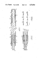
- Cylindrical body member 12 of apparatus 10 of the present invention is milled out to accept notched cylindrical hard rubber sleeves or packers 13 in two separate annular grooves 14, 16. Pairs of threaded and flanged clamps 20, 22 are screwed into externally threaded body member 12 and secured by threaded end cap 24 in such a manner as to stretch and squeeze the rubber sleeves 13 against the outside wall of apparatus 10. Beveled nylon expanding anti-extrusions rings 30 are inserted at either extremity of rubber sleeves or packers 13 to prevent them from extruding out once the system is energized.
- Apparatus 10 is inserted inside a pipe 25 and coupling 27 connection to be tested and pressurized fluid is injected at inlet 38 an through passageway 40 which is connected to openings 42, 44 directly beneath rubber sleeves 13a, 13b respectively. Since rubber sleeves 13 are clamped to body member 12 of apparatus 10 by squeeze clamps 20, 22, the interior pressure forces the rubber to balloon out and come into contact with the interior surface 26 of pipe 25 into which apparatus 10 has been inserted, best seen in FIGS. 4 and 5. Once these sleeves or packers 13 have been properly energized, inlet 38 of passageway 40 is closed off with a valve (not shown) to hold that pressure on the sleeves or packers 13.
- Seal rings 110 of FIG. 6 of this application are identical to seal rings 10 of FIG. 3 of the parent;
- Apparatus 112 of FIG. 6 of this application is identical to apparatus 12 of FIG. 3 of the parent; and, external threads 113 of FIG. 6 of this application is identical to external threads 13 of FIG. 3 of the parent.
Abstract
An apparatus for testing the connection between a segment of pipe and a coupling comprising a cylindrical body member adapted to be inserted inside one end of the pipe segment, the body member having provided therein a plurality of hydrostatically operated pressure resistant sealing packers that are spaced apart and are forced laterally outwardly of the cylindrical body and into contact with the inner surface of the pipe segment and coupling, thereby sealing off the interior of the pipe segment so as to isolate a test fluid introduced under pressure in the annular space created between the sealing packers; and an inlet port in one end of the cylindrical body member and a fluid passageway provided longitudinally within the cylindrical body member and communicating with the inlet port and the annular space for admitting test fluid under pressure into the annular space.
Description
This application is a continuation-in-part application of a previous application by the same inventor bearing U.S. Ser. No. 698,030 filed Feb. 4, 1985 and now U.S. Pat. No. 4,617,823. The entire previous application Ser. No. 698,030 is incorporated herein by refernce as if set forth in full below.
1. Field of the Invention
The current invention relates to an apparatus employed to seal off the interior of tubular members such as a cylindrical pipe or coupling. This relates to an apparatus which in one application is employed to seal off a particular section of pipe by using two of these such devices spaced apart and filling the annular space created between them with a liquid or gas under high pressure in order to check the strength of the pipe's outer wall. In another application these "packers" are used to seal off the inside diameter (I.D.) of a pipe and the inside diameter of a coupling that is screwed onto that pipe, thus creating an annulus between them which includes the "made up" connection. Fluid is then injected into this annulus to test the integrity of the connection between the male threads on the pipe and the female threads on the coupling.
2. General Background
In the oil and gas production industry tubing sections of threaded pipe are joined end-to-end, i.e. pin to box end, to convey fluids. It is desirable that the joints be strong and of tight fit and that the body wall be strong enough to withstand relatively high internal pressures. It is common practice in the oil and gas industry to plug off the ends of each particular joint by screwing test plugs onto the respective threaded ends and to fill the inside of the pipe with a fluid under high pressure to check for leaks behind the collar. Evidence of any leaks when pressured up to a standardized test pressure is an indication that either the external threads on the pin end or the internal threads on the coupling were improperly machined and thus not mating properly, or that they may not have been screwed together with adequate torque or that the body wall was of insufficient strength to withstand the pressure. This test procedure is followed to simulate "down hole" conditions when there is pressure exerted on the connections.
This procedure is very inefficient due to the need to fill up the entire inside of the full length of the tubing with fluid. Often the same pipe is pressure tested several times at the mill, at the threading facility and in the storage yard. After the full length of the body has been tested at the mill, subsequent tests are only necessary to check the integrity of the threaded connections or the coupling connection. Full length pressure testing with screw and plugs is inefficient, time consuming and very dangerous due to the large volume of water combined with the high test pressures. Test plugs sometimes blow out causing great physical damage to equipment and personnel. There is also potential gauling damage to the threads on the pipe which are screwed into the mated test plugs.
The apparatus of the present invention is used to perform a similar pressure test on the pipe threads, but due to the isolation of the annular space to the connection area has radically reduced the volume and surface area that is exerted upon the plug. The innovation of design of the present invention has eliminated the safety hazard of conventional pressure testing and at the same time streamlined the efficiency of the testing procedure requiring only small volume, high pressure pumps and only small quantities of test fluid. Resulting equipment needed to operate these plugs is a small fraction of the size, weight, and cost of those types of pumping, power and water storage units associated with conventional pressure testing.
The apparatus of the present invention is also used to test the made up connections on tubing strings as they are being assembled at the rig site. As each joint is screwed to the one below it on the rig floor, the apparatus of the present invention is inserted into the pipe and set in such a manner that one of the plugs is directly below each threaded connection and the other plug is directly above the connection. The annulus created between these two plugs or packers is then filled and pressured with a fluid to test the integrity of the made up connection. Due to simplified design of the apparatus of the present invention and the reduced volume of test fluid needed to fill the contained annulus, it is possible to operate this equipment with pumps that are a fraction of the size used with conventional methods.
U.S. Pat. No. 2,663,183 issued to F. Huhn and is entitled "Tube Testing Apparatus." This patent discloses a tester adapted to be screwed into the open end of a pipe coupling which is in turn screwed onto the threaded end of a tube or well casing.
U.S. Pat. No. 2,241,526 issued to M. Rosenkranz and is entitled "Pipe Joint Tester" and discloses an apparatus for testing a pipe joint by confining fluid under pressure to the joint area. This device also comprises, as with the Huhn, U.S. Pat. No. 2,663,183, a tester member having seal members spaced apart so as to seal off the area of the pipe connection to be tested and, after the seal is effected, providing a testing fluid internally to the joint through a passageway arranged axially in the body member.
U.S. Pat. No. 2,246,885 issued to G. H. Jones and is entitled "Pipe Joint Tester" and discloses a device for testing the joint by introducing interiorly of the joint to be tested fluid under pressure which is confined solely to the joint area.
U.S. Pat. No. 2,695,632 issued to M. C. Brock and is entitled "Coupling Tester" and discloses an apparatus for testing tool joints providing a mandrel with an axial bore closed at one end, sealing members to engage the interior wall of the pipe proximate either end thereof and laterally communicating ports in the mandrel such that it communicates test fluid to the connections securing the tool joint to the pipe.
U.S. Pat. No. 3,034,339 issued to P. A. Gawlik and is entitled "Tool For Detecting Pipe Leaks."
U.S. Pat. No. 4,136,552 issued to M. M. Hasha and is entitled "Leak Testing Method And Apparatus For Tubular Members And Packer Means Therefor."
U.S. Pat. No. 4,152,926 also issued to M. M. Hasha and is entitled "Method And Apparatus For Testing The Connections Between Pipe Segments."
U.S. Pat. No. 3,653,254 issued to T. A. Simon and is entitled "Leak-Testing Internal Seals And Pipe Joints.
For further understanding of the nature and objects of the present invention, reference should be had to the following detailed description taken in conjunction with the accompanying drawings, in which like parts are given like reference numerals and wherein:
FIG. 1 is an elevational view in section of the preferred embodiment of the apparatus of the present invention arranged for down hole testing of the present invention;
FIG. 2 is an elevational view, partly in section, of the preferred embodiment of the apparatus of the present invention as it is adapted to test a mill end connection with one packer sealing in the internal diameter (I.D.) of the pin and the other in the I.D. of the coupling;
FIG. 3 is an elevational view of the various interchangeable weight rings which are used to adapt the apparatus of the present invention to test the various different weights of pipe;
FIG. 4 is an elevatioal view of the preferred embodiment of the apparatus of the present invention showing the apparatus inserted inside a "made up" connection as it would be used to test that connection, this FIGURE showing the apparatus in its "inactive" position;
FIG. 5 is an elevational view of the preferred embodiment of the apparatus of the present invention showning the apparatus of FIG. 4 in the active or "testing" position; and,
FIG. 6 is an elevational view, partly in section, of the preferred embodiment of the apparatus of Ser. No. 698,030, now U.S. Pat. No. 4,617,823 issued Oct. 21, 1986, in its operational state wherein it is inserted inside a coupling and pipe that are already assembled together.
To avoid confusion by duplication of numbering between new FIG. 6 of this application and FIG. 3 of the parent application incorporated by reference (Ser. No. 698,030 now U.S. Pat. No. 4,617,823 issued Oct. 21, 1986), the following explanation is provided: Seal rings 110 of FIG. 6 of this application are identical to seal rings 10 of FIG. 3 of the parent; Apparatus 112 of FIG. 6 of this application is identical to apparatus 12 of FIG. 3 of the parent; and, external threads 113 of FIG. 6 of this application is identical to external threads 13 of FIG. 3 of the parent.
Claims (5)
1. An apparatus for testing the connection between a segment of pipe and a coupling comprising:
a. a cylindrical body member adapted to be inserted inside one end of said pipe segment, said body member having provided therein a plurality of hydrostatically operated pressure resistant first sealing means that are spaced apart and that contact at each end thereof means for preventing the extrusion of said first sealing means during testing, said preventing means arranged annularly of said cylindrical body member between said first sealing means and the first end portion of clamping means provided internally and longitudinally of said cylindrical body member, thereby forcing said first sealing means laterally outwardly of said cylindrical body and into contact with the inner surface of said pipe segment and coupling being tested, thereby sealing off the interior of said pipe segment so as to isolate a test fluid introduced under pressure to the area surrounding the connection between said pipe and said cylindrical body member and between said spaced apart first sealing means;
b. a cylindrical nipple-like second pressure resistant sealing means arranged at one end of said cylindrical body member that threadably engages exposed interior threads of said coupling; and,
c. means for admitting test fluid under pressure into the annular space created between said hydrostatically activated first sealing means and said cylindrical nipple-like second sealing means, said means for admitting test fluid including a first fluid passageway provided longitudinally of said cylindrical body member for introducing said testing fluid under pressure into said annular space.
2. The apparatus of claim 1, further comprising means for confining said test fluid under pressure to the connection area between said pipe segment and said cylindrical body member.
3. The apparatus of claim 1, wherein said second sealing means comprises a metal-to-metal seal formed by the external threads of said apparatus threadably engaging the interior threads of said coupling.
4. The apparatus of claim 1, wherein said testing device creates an internal seal on the interior surface of said pipe whereby said testing fluid under pressure is confined to said connection area.
5. The apparatus of claim 1, wherein said means for admitting test fluid under pressure into said annular space, further includes a second passageway in fluid communication with said first passageway and extending transversely through at least a portion of said cylindrical body member and an inlet port in fluid communication with said first passageway and a source of fluid under pressure.
Priority Applications (3)
| Application Number | Priority Date | Filing Date | Title |
|---|---|---|---|
| US06/807,756 US4733554A (en) | 1985-02-04 | 1985-12-11 | Hydro pressure thread tester |
| PCT/US1986/002649 WO1987003686A1 (en) | 1985-12-11 | 1986-12-08 | Hydro pressure thread tester |
| EP19870900501 EP0248893A4 (en) | 1985-12-11 | 1986-12-08 | Hydro pressure thread tester. |
Applications Claiming Priority (2)
| Application Number | Priority Date | Filing Date | Title |
|---|---|---|---|
| US06/698,030 US4617823A (en) | 1985-02-04 | 1985-02-04 | Hydro pressure thread tester |
| US06/807,756 US4733554A (en) | 1985-02-04 | 1985-12-11 | Hydro pressure thread tester |
Related Parent Applications (1)
| Application Number | Title | Priority Date | Filing Date |
|---|---|---|---|
| US06/698,030 Continuation-In-Part US4617823A (en) | 1985-02-04 | 1985-02-04 | Hydro pressure thread tester |
Publications (1)
| Publication Number | Publication Date |
|---|---|
| US4733554A true US4733554A (en) | 1988-03-29 |
Family
ID=25197109
Family Applications (1)
| Application Number | Title | Priority Date | Filing Date |
|---|---|---|---|
| US06/807,756 Expired - Fee Related US4733554A (en) | 1985-02-04 | 1985-12-11 | Hydro pressure thread tester |
Country Status (3)
| Country | Link |
|---|---|
| US (1) | US4733554A (en) |
| EP (1) | EP0248893A4 (en) |
| WO (1) | WO1987003686A1 (en) |
Cited By (8)
| Publication number | Priority date | Publication date | Assignee | Title |
|---|---|---|---|---|
| US5426676A (en) * | 1993-10-22 | 1995-06-20 | Westinghouse Electric Corporation | Extrusion-resistant seal assembly |
| US5438862A (en) * | 1994-02-14 | 1995-08-08 | Westinghouse Elec Corp | System and method for in situ testing of the leak-tightness of a tubular member |
| US5563336A (en) * | 1995-09-13 | 1996-10-08 | Mallet; Ronald J. | Appparatus for pressure testing of tubulars |
| US5665903A (en) * | 1996-10-21 | 1997-09-09 | Moran; William John | Technique for testing pipe couplings for defects |
| US6430990B1 (en) * | 2000-11-10 | 2002-08-13 | Ronald J. Mallet | Pipe testing apparatus |
| DE19545383B4 (en) * | 1994-12-06 | 2005-10-27 | Ritter Leckortung Gmbh | A method for locating a leak on a domestic connection pipe of a drinking water supply network and arrangement for leak detection using the method |
| US8739607B2 (en) | 2009-03-16 | 2014-06-03 | Noetic Engineering 2008 Inc. | Fixture for evaluating a metal-to-metal seal between tubular components and method of use of same |
| US20150076809A1 (en) * | 2012-03-12 | 2015-03-19 | Pioneer Lining Technology Limited | Electrofusion Fittings and Methods |
Families Citing this family (1)
| Publication number | Priority date | Publication date | Assignee | Title |
|---|---|---|---|---|
| CN107084821B (en) * | 2017-07-03 | 2019-03-29 | 中国石油大学(华东) | A kind of high temperature and pressure horizontal well packer simulation test device |
Citations (7)
| Publication number | Priority date | Publication date | Assignee | Title |
|---|---|---|---|---|
| US2241526A (en) * | 1939-09-12 | 1941-05-13 | Nat Tube Co | Pipe joint tester |
| US3199598A (en) * | 1962-07-02 | 1965-08-10 | Loomis Jean Doyle | Apparatus for testing and repairing well pipes |
| US3478577A (en) * | 1968-03-18 | 1969-11-18 | Ernest D Hauk | Apparatus and method for testing well pipe |
| US3503249A (en) * | 1968-05-10 | 1970-03-31 | Joseph Frank Dumond | Tool for testing pipe joints |
| US3795138A (en) * | 1971-03-25 | 1974-03-05 | M Hasha | Method of stage internal pressure testing connections between tubular members |
| US4081990A (en) * | 1976-12-29 | 1978-04-04 | Chatagnier John C | Hydraulic pipe testing apparatus |
| US4548069A (en) * | 1983-04-26 | 1985-10-22 | Damco Testers, Inc. | Pipe testing tool |
Family Cites Families (8)
| Publication number | Priority date | Publication date | Assignee | Title |
|---|---|---|---|---|
| US2246885A (en) * | 1939-10-10 | 1941-06-24 | Nat Tube Co | Pipe joint tester |
| US2695632A (en) * | 1951-03-26 | 1954-11-30 | Houston Oil Field Mat Co Inc | Coupling tester |
| US2663183A (en) * | 1951-04-26 | 1953-12-22 | Western Inspection Company Inc | Tube testing apparatus |
| US2793524A (en) * | 1954-11-17 | 1957-05-28 | Exxon Research Engineering Co | Tubing joint leak detector |
| US3034339A (en) * | 1957-10-17 | 1962-05-15 | Paul P Flusche | Tool for detecting pipe leaks |
| US3653254A (en) * | 1970-10-16 | 1972-04-04 | Shell Oil Co | Leak-testing internal seals in pipe joints |
| US4132111A (en) * | 1974-05-06 | 1979-01-02 | Hasha Malvern M | Leak testing method and apparatus for tubular members packer means therefor |
| US4152926A (en) * | 1977-11-07 | 1979-05-08 | Hasha Malvern M | Method and apparatus for testing the connections between pipe segments |
-
1985
- 1985-12-11 US US06/807,756 patent/US4733554A/en not_active Expired - Fee Related
-
1986
- 1986-12-08 WO PCT/US1986/002649 patent/WO1987003686A1/en not_active Application Discontinuation
- 1986-12-08 EP EP19870900501 patent/EP0248893A4/en not_active Withdrawn
Patent Citations (7)
| Publication number | Priority date | Publication date | Assignee | Title |
|---|---|---|---|---|
| US2241526A (en) * | 1939-09-12 | 1941-05-13 | Nat Tube Co | Pipe joint tester |
| US3199598A (en) * | 1962-07-02 | 1965-08-10 | Loomis Jean Doyle | Apparatus for testing and repairing well pipes |
| US3478577A (en) * | 1968-03-18 | 1969-11-18 | Ernest D Hauk | Apparatus and method for testing well pipe |
| US3503249A (en) * | 1968-05-10 | 1970-03-31 | Joseph Frank Dumond | Tool for testing pipe joints |
| US3795138A (en) * | 1971-03-25 | 1974-03-05 | M Hasha | Method of stage internal pressure testing connections between tubular members |
| US4081990A (en) * | 1976-12-29 | 1978-04-04 | Chatagnier John C | Hydraulic pipe testing apparatus |
| US4548069A (en) * | 1983-04-26 | 1985-10-22 | Damco Testers, Inc. | Pipe testing tool |
Cited By (9)
| Publication number | Priority date | Publication date | Assignee | Title |
|---|---|---|---|---|
| US5426676A (en) * | 1993-10-22 | 1995-06-20 | Westinghouse Electric Corporation | Extrusion-resistant seal assembly |
| US5438862A (en) * | 1994-02-14 | 1995-08-08 | Westinghouse Elec Corp | System and method for in situ testing of the leak-tightness of a tubular member |
| DE19545383B4 (en) * | 1994-12-06 | 2005-10-27 | Ritter Leckortung Gmbh | A method for locating a leak on a domestic connection pipe of a drinking water supply network and arrangement for leak detection using the method |
| US5563336A (en) * | 1995-09-13 | 1996-10-08 | Mallet; Ronald J. | Appparatus for pressure testing of tubulars |
| US5665903A (en) * | 1996-10-21 | 1997-09-09 | Moran; William John | Technique for testing pipe couplings for defects |
| US6430990B1 (en) * | 2000-11-10 | 2002-08-13 | Ronald J. Mallet | Pipe testing apparatus |
| US8739607B2 (en) | 2009-03-16 | 2014-06-03 | Noetic Engineering 2008 Inc. | Fixture for evaluating a metal-to-metal seal between tubular components and method of use of same |
| US20150076809A1 (en) * | 2012-03-12 | 2015-03-19 | Pioneer Lining Technology Limited | Electrofusion Fittings and Methods |
| US9377148B2 (en) * | 2012-03-12 | 2016-06-28 | Pioneer Lining Technology Limited | Electrofusion fittings and methods |
Also Published As
| Publication number | Publication date |
|---|---|
| EP0248893A1 (en) | 1987-12-16 |
| WO1987003686A1 (en) | 1987-06-18 |
| EP0248893A4 (en) | 1990-06-05 |
Similar Documents
| Publication | Publication Date | Title |
|---|---|---|
| EP0857297B1 (en) | A device for detecting leakage in flange joints | |
| US3165920A (en) | Tool for testing pipe with water and gas simultaneously | |
| US3371521A (en) | Leak-testing apparatus for either flush or shouldered pipe joints and packer therefor | |
| US4152924A (en) | Sub-sea equipment test and isolation tool | |
| US4132111A (en) | Leak testing method and apparatus for tubular members packer means therefor | |
| US3165919A (en) | Method and apparatus for testing well pipe such as casing or flow tubing | |
| US5066208A (en) | Pipe joint testing and grouting unit | |
| NZ194585A (en) | Method and tool for testing for leaks in pipes and tubes | |
| CN104568418B (en) | Packer performance detecting device | |
| US4733554A (en) | Hydro pressure thread tester | |
| US2478628A (en) | Testing casing heads | |
| US2998721A (en) | Tool for detecting pipe leaks | |
| CN102418839B (en) | Sealing detection device for threads of pipe fitting in pipeline | |
| US4548069A (en) | Pipe testing tool | |
| US3499469A (en) | Self sealing pressure plug | |
| US4852394A (en) | Anti-extrusion sealing means | |
| US4136552A (en) | Leak testing method and apparatus for tubular members and packer means therefor | |
| US7219736B1 (en) | Externally testable redundant connections for subsea wells | |
| US4519238A (en) | Apparatus for internally testing a plurality of interconnected pipe sections | |
| US2663183A (en) | Tube testing apparatus | |
| US4617823A (en) | Hydro pressure thread tester | |
| US6430990B1 (en) | Pipe testing apparatus | |
| US3034339A (en) | Tool for detecting pipe leaks | |
| US2851111A (en) | Pneumatic packer | |
| US2695632A (en) | Coupling tester |
Legal Events
| Date | Code | Title | Description |
|---|---|---|---|
| FEPP | Fee payment procedure |
Free format text: PAYOR NUMBER ASSIGNED (ORIGINAL EVENT CODE: ASPN); ENTITY STATUS OF PATENT OWNER: SMALL ENTITY |
|
| FPAY | Fee payment |
Year of fee payment: 4 |
|
| REMI | Maintenance fee reminder mailed | ||
| LAPS | Lapse for failure to pay maintenance fees | ||
| FP | Lapsed due to failure to pay maintenance fee |
Effective date: 19960403 |
|
| STCH | Information on status: patent discontinuation |
Free format text: PATENT EXPIRED DUE TO NONPAYMENT OF MAINTENANCE FEES UNDER 37 CFR 1.362 |