US4737010A - Spreader head for an optical fiber cable - Google Patents
Spreader head for an optical fiber cable Download PDFInfo
- Publication number
- US4737010A US4737010A US06/919,397 US91939786A US4737010A US 4737010 A US4737010 A US 4737010A US 91939786 A US91939786 A US 91939786A US 4737010 A US4737010 A US 4737010A
- Authority
- US
- United States
- Prior art keywords
- optical fiber
- ring
- cable
- fiber cable
- shells
- Prior art date
- Legal status (The legal status is an assumption and is not a legal conclusion. Google has not performed a legal analysis and makes no representation as to the accuracy of the status listed.)
- Expired - Fee Related
Links
Images

Classifications
-
- G—PHYSICS
- G02—OPTICS
- G02B—OPTICAL ELEMENTS, SYSTEMS OR APPARATUS
- G02B6/00—Light guides; Structural details of arrangements comprising light guides and other optical elements, e.g. couplings
- G02B6/44—Mechanical structures for providing tensile strength and external protection for fibres, e.g. optical transmission cables
- G02B6/4439—Auxiliary devices
- G02B6/4471—Terminating devices ; Cable clamps
- G02B6/4472—Manifolds
-
- G—PHYSICS
- G02—OPTICS
- G02B—OPTICAL ELEMENTS, SYSTEMS OR APPARATUS
- G02B6/00—Light guides; Structural details of arrangements comprising light guides and other optical elements, e.g. couplings
- G02B6/24—Coupling light guides
- G02B6/36—Mechanical coupling means
- G02B6/38—Mechanical coupling means having fibre to fibre mating means
- G02B6/3807—Dismountable connectors, i.e. comprising plugs
- G02B6/3873—Connectors using guide surfaces for aligning ferrule ends, e.g. tubes, sleeves, V-grooves, rods, pins, balls
- G02B6/3885—Multicore or multichannel optical connectors, i.e. one single ferrule containing more than one fibre, e.g. ribbon type
-
- G—PHYSICS
- G02—OPTICS
- G02B—OPTICAL ELEMENTS, SYSTEMS OR APPARATUS
- G02B6/00—Light guides; Structural details of arrangements comprising light guides and other optical elements, e.g. couplings
- G02B6/44—Mechanical structures for providing tensile strength and external protection for fibres, e.g. optical transmission cables
- G02B6/4401—Optical cables
- G02B6/4415—Cables for special applications
- G02B6/4427—Pressure resistant cables, e.g. undersea cables
- G02B6/4428—Penetrator systems in pressure-resistant devices
Definitions
- the present invention relates to a spreader head for an optical fiber cable, with the cable being constituted by a central grooved core with each groove receiving a bundle of optical fibers.
- Spreader heads exist for spreading out the fiber bundles of a cable, with each bundle being received in a flexible protective tube. Other spreader heads also exist for spreading out the individual optical fibers of a bundle as received in each of said flexible protective tubes.
- preferred embodiments of the present invention enable an optical fiber cable to be spread out directly into individual optical fibers.
- Such preferred embodiments of the present invention also make such a cable highly flexible in use during various repair and other operations which may be performed on the cable and additionally they make use of components which are common to various different sizes of cable head and to various different cable configurations, together with other components which are specially adapted to a given size of cable head or to a given cable configuration.
- the present invention provides a spreader head for an optical fiber cable, the cable comprising a central grooved core with each groove receiving a bundle of optical fibers, the spreader head being constituted by a support part surrounded by a ring having outwardly open recesses disposed around its periphery and each receiving a cylinder, with each cylinder having at least as many axial orifices as there are optical fibers to a single bundle of optical fibers, and with each axial orifice having an optical fiber passing therethrough being extended by a flexible tube for surrounding and protecting the corresponding optical fiber.
- a spreader head preferably includes at least one of the following features:
- each recess receives a centering peg which engages into a corresponding orifice in the cylinder received in the recess;
- said head is covered by two half-shells, with at least one of said half-shells including a projection for preventing it from rotating;
- the ring of the support part extends axially in the form of a cable-holding tube, with said tube having a pointed screw passing radially therethrough to lock the axial position of the cable relative thereto.
- a spreader head for a 10-groove optical fiber cable having a bundle of four fibers in each groove is described by way of example with reference to the accompanying drawings, in which:
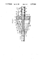
- FIG. 1 is a longitudinal section through a complete spreader head on a line I--I of FIG. 2;
- FIG. 2 is a partially cutaway end view of the FIG. 1 head seen along arrow II;
- FIG. 3 is a front view of a single cylinder
- FIG. 4 is a longitudinal section on line IV of the cylinder shown in FIG. 3.
- FIG. 1 shows a completed spreader head with a cable fully mounted thereon.
- a cable 10 is connected to a spreader head which is essentially constituted by three main components: a support part 20, a plurality of cylinders 30, and two half-shells 40.
- the cable 10 comprises a core 11 having ten helical grooves 12 (which grooves could alternatively follow an alternating or sinuous pitch), with each groove receiving a bundle 13 of optical fibers.
- the cable is fitted with a protective covering 14, but the covering is removed over a length which is substantially equal to the length of the head.
- Each end of the protective covering on either side of the window formed therein is heId in place by binding 15.
- the support part 20 comprises two main portions, a ring 21 having cylindrical cross section recesses 23 which are seen more clearly in FIG. 2, and a holding tube 22 into which the cable 10 is threaded, with the tube receiving a pointed screw 25 for locking the axial position of the cable.
- Each recess 23 receives a corresponding cylinder 30 and each cylinder is prevented from rotating by a corresponding peg 33.
- Each cylinder 30 has a plurality of spaced orifices 31 including inlets 31A or receiving individual fibers of a bundle 13 constituted by four optical fibers 13A, 13B, 13C and 13D, and outlets fitted with four respective protective flexible tubes 50 each of which encloses a single optical fiber.
- the outlet side is shown with only the optical fiber 13B and its tube 50.
- the head is covered by two half-shells 40 eaoh of which bears at one end on binding 15 and at the other end on the cylinders 30.
- the two half-shells 40 are held together by two collars 43.
- Each of the half-shells includes a groove 41 for receiving rounded portions 24 of "petals" defining the periphery of the ring 21.
- FIG. 2 shows the shape of the ring 21 with its ten recesses 23, and with each adjacent pair of recesses 23 being separated by a rounded radially projecting portion 24 of the ring 21.
- the recesses 23 and the rounded portions 24 give the ring a "daisy” shape with pairs of adjacent "petals” which are sufficiently flexible to receive the cylinders 30 in the recesses 23 by snap-fastening.
- FIG. 2 also shows the two half-shells 40 bearing against the cylinders 30 and the partially cutaway portion shows how the rounded portions 24 of "petals" at the periphery of the ring 21 is received in the groove 41 of the half-shells 40.
- These half-shells 40 each include a projection 42 (also visible in FIG. 1) which fits between two adjacent cylinders 30, said projections preventing the half-shells from rotating.
- FIG. 3 shows a single cylinder 30 in greater detail with four orifices 31 having corresponding chamfered inlets 31A. Each of these four orifices encloses a corresponding optical fiber, i.e. optical fibers 13A, 13B, 13C, and 13D of the bundle 13.
- Each cylinder also includes a blind, radial hole 32 for receiving a centering peg 33. It will be understood that if each bundle includes more than four fibers, each cylinder could include other longitudinally extending orifices 31 for receiving the extra fibers, so long as the orifices avoid the region occupied by the blind hole 32.
- FIG. 4 shows the position of a flexible tube 50 inside an orifice 31 through a cylinder 30.
- the tube 50 runs along practically the entire length of the orifice and it may be held in place by gluing, for example.
- each cylinder is greater than the corresponding width of the ring and that therefore each end of each cylinder projects slightly beyond the corresponding face of the ring, thereby facilitating extraction by means of a suitable tool.
- a cable is spread out as follows:
- the cable to be spread out is prepared by removing its protective covering 14 from a portion whose length is substantially equal to the lenqth of the spreader head, and this bare portion of cable is provided at a distance from the end of the cable which corresponds to the lengths of the optical fibers which are to be inserted into the flexible protective tubes;
- each end of the bared window of cable is bound at 15 in order to prevent the edges of the protective covering from being damaged;
- the support part 20 is threaded over the cable up to the window;
- the head is rested on a suitable support (not shown) after all of the tubes 50 have been previously threaded through the corresponding cylinders 30;
- each of the fibers from a given bundle is extracted one by one from that bundle and is coiled temporarily into an auxiliary container, and then each of the fibers is threaded into a corresponding tube 50 which is identified by a suitable color code;
- the pointed screw 24 is screwed home to hold the support part 20 relative to the cable 10;
- the two half-shells 50 are put into place and then fixed together by means of the two collars 43.
Landscapes
- Physics & Mathematics (AREA)
- General Physics & Mathematics (AREA)
- Optics & Photonics (AREA)
- Light Guides In General And Applications Therefor (AREA)
- Mechanical Coupling Of Light Guides (AREA)
- Optical Fibers, Optical Fiber Cores, And Optical Fiber Bundles (AREA)
Abstract
Description
Claims (6)
Applications Claiming Priority (2)
| Application Number | Priority Date | Filing Date | Title |
|---|---|---|---|
| FR8515342A FR2588670B1 (en) | 1985-10-16 | 1985-10-16 | BREAKING HEAD OF A FIBER OPTIC CABLE |
| FR8515342 | 1985-10-16 |
Publications (1)
| Publication Number | Publication Date |
|---|---|
| US4737010A true US4737010A (en) | 1988-04-12 |
Family
ID=9323880
Family Applications (1)
| Application Number | Title | Priority Date | Filing Date |
|---|---|---|---|
| US06/919,397 Expired - Fee Related US4737010A (en) | 1985-10-16 | 1986-10-16 | Spreader head for an optical fiber cable |
Country Status (6)
| Country | Link |
|---|---|
| US (1) | US4737010A (en) |
| EP (1) | EP0225986B1 (en) |
| JP (1) | JPS6294808A (en) |
| CA (1) | CA1270683A (en) |
| DE (1) | DE3682571D1 (en) |
| FR (1) | FR2588670B1 (en) |
Cited By (14)
| Publication number | Priority date | Publication date | Assignee | Title |
|---|---|---|---|---|
| US4830457A (en) * | 1986-12-05 | 1989-05-16 | The Furukawa Electric Co., Ltd. | Optical cable connecting section in electric power and optical composite cable |
| US4884862A (en) * | 1988-10-17 | 1989-12-05 | Minnesota Mining And Manufacturing Company | Fiber optic fan-out module |
| EP0392679A1 (en) * | 1989-04-14 | 1990-10-17 | Sumitomo Electric Industries, Ltd. | Branch device for multi-core optical fiber |
| US4978194A (en) * | 1989-08-28 | 1990-12-18 | Raynet Corporation | Stepped cable block |
| US5013125A (en) * | 1989-10-02 | 1991-05-07 | Alcatel Na Cable Systems Inc. | Pulling eye assembly for connectorized optical fiber cables |
| US5142601A (en) * | 1990-06-21 | 1992-08-25 | The Furukawa Electric Co., Ltd. | Optical connector and a method for assembling the same |
| WO1992015911A1 (en) * | 1991-03-01 | 1992-09-17 | Fibernet Research Pty. Ltd. | Fibre separator |
| US5491766A (en) * | 1993-04-16 | 1996-02-13 | Raychem Corporation | Bonding assembly for fiber optic cable and associated method |
| US5751882A (en) * | 1993-04-01 | 1998-05-12 | N.V. Raychem S.A. | Optical fibre organizer |
| US6687450B1 (en) | 2000-05-15 | 2004-02-03 | Tyco Electronics Raychem Nv | Break-out device |
| US20050084220A1 (en) * | 2002-01-09 | 2005-04-21 | Tull Michael A. | Underwater vehicles |
| US20080279506A1 (en) * | 2004-12-22 | 2008-11-13 | John Kerry | Blown Optical Fibre Multi-Tube Terminal Connectors |
| US20170357050A1 (en) * | 2015-03-18 | 2017-12-14 | Japan Aviation Electronics Industry, Limited | Optical fiber cable assembly and measurement device |
| US10359590B2 (en) | 2016-04-04 | 2019-07-23 | Opterna Technology Limited | Fiber optic cable deployment assemblies, systems, and methods |
Families Citing this family (5)
| Publication number | Priority date | Publication date | Assignee | Title |
|---|---|---|---|---|
| FR2606519B1 (en) * | 1986-11-07 | 1990-07-13 | Pouliquen Georges | SEALING DEVICE FOR PRESSURIZED OPTICAL CABLE AND DEPRESSURIZING CABLE DETECTION SYSTEM USING SUCH A DEVICE |
| IT1222135B (en) * | 1987-07-27 | 1990-09-05 | Pirelli Cavi Spa | SUBMARINE LINE FOR FIBER OPTIC TELECOMMUNICATIONS |
| FR2646928B1 (en) * | 1989-05-11 | 1993-12-24 | Etat Francais Cnet | MODULE AND CONNECTION BOX FOR FIBER OPTIC CABLES |
| GB8922355D0 (en) * | 1989-10-04 | 1989-11-22 | British Telecomm | Sealing gland |
| FR2662270B1 (en) * | 1990-05-17 | 1992-07-24 | Alcatel Cable | DEVICE AND METHOD FOR GROWING OPTICAL FIBERS BEYOND A SHEATHED CABLE END. |
Citations (11)
| Publication number | Priority date | Publication date | Assignee | Title |
|---|---|---|---|---|
| GB1470890A (en) * | 1975-10-01 | 1977-04-21 | Post Office | Cables |
| EP0017319A2 (en) * | 1979-02-27 | 1980-10-15 | THE PLESSEY COMPANY plc | Optical cable connector for sealed containers |
| JPS55138066A (en) * | 1979-04-16 | 1980-10-28 | Nippon Steel Corp | One side machined galvanized steel plate and production of the same |
| US4261640A (en) * | 1979-04-03 | 1981-04-14 | Harris Corporation | In-line optic attenuators for optical fibers |
| EP0051510A1 (en) * | 1980-11-03 | 1982-05-12 | Lignes Telegraphiques Et Telephoniques L.T.T. | Optical fibres positioning device in a piece forming ferrule destined to connect two transmission cables by optical fibres |
| JPS57160797A (en) * | 1981-03-31 | 1982-10-04 | Fuji Heavy Ind Ltd | Vtol plane |
| EP0063506A1 (en) * | 1981-04-03 | 1982-10-27 | Lignes Telegraphiques Et Telephoniques L.T.T. | Protection device for open optical fibres at the end of a cable element, cable element with said device, and application of such a cable element |
| US4359262A (en) * | 1980-06-30 | 1982-11-16 | Northern Telecom Limited | Tray for organizing optical fiber splices and enclosures embodying such trays |
| JPS58158609A (en) * | 1982-03-16 | 1983-09-20 | Nippon Telegr & Teleph Corp <Ntt> | Waterproof termination part of optical fiber cable |
| FR2534700A1 (en) * | 1982-10-19 | 1984-04-20 | Silec Liaisons Elec | Device for separating and protecting optical fibres from an optical cable. |
| JPS6061704A (en) * | 1983-09-16 | 1985-04-09 | Nippon Telegr & Teleph Corp <Ntt> | Mechanical strength holding part of optical cable sheath connecting part |
Family Cites Families (2)
| Publication number | Priority date | Publication date | Assignee | Title |
|---|---|---|---|---|
| JPS5762007A (en) * | 1980-10-02 | 1982-04-14 | Fujitsu Ltd | Stub cable dam for communication |
| JPS5950413A (en) * | 1982-09-17 | 1984-03-23 | Nippon Telegr & Teleph Corp <Ntt> | Connecting mechanism of submarine optical fiber cable |
-
1985
- 1985-10-16 FR FR8515342A patent/FR2588670B1/en not_active Expired
-
1986
- 1986-10-14 DE DE8686114214T patent/DE3682571D1/en not_active Expired - Lifetime
- 1986-10-14 EP EP86114214A patent/EP0225986B1/en not_active Expired - Lifetime
- 1986-10-14 JP JP61243992A patent/JPS6294808A/en active Pending
- 1986-10-15 CA CA000520530A patent/CA1270683A/en not_active Expired - Fee Related
- 1986-10-16 US US06/919,397 patent/US4737010A/en not_active Expired - Fee Related
Patent Citations (11)
| Publication number | Priority date | Publication date | Assignee | Title |
|---|---|---|---|---|
| GB1470890A (en) * | 1975-10-01 | 1977-04-21 | Post Office | Cables |
| EP0017319A2 (en) * | 1979-02-27 | 1980-10-15 | THE PLESSEY COMPANY plc | Optical cable connector for sealed containers |
| US4261640A (en) * | 1979-04-03 | 1981-04-14 | Harris Corporation | In-line optic attenuators for optical fibers |
| JPS55138066A (en) * | 1979-04-16 | 1980-10-28 | Nippon Steel Corp | One side machined galvanized steel plate and production of the same |
| US4359262A (en) * | 1980-06-30 | 1982-11-16 | Northern Telecom Limited | Tray for organizing optical fiber splices and enclosures embodying such trays |
| EP0051510A1 (en) * | 1980-11-03 | 1982-05-12 | Lignes Telegraphiques Et Telephoniques L.T.T. | Optical fibres positioning device in a piece forming ferrule destined to connect two transmission cables by optical fibres |
| JPS57160797A (en) * | 1981-03-31 | 1982-10-04 | Fuji Heavy Ind Ltd | Vtol plane |
| EP0063506A1 (en) * | 1981-04-03 | 1982-10-27 | Lignes Telegraphiques Et Telephoniques L.T.T. | Protection device for open optical fibres at the end of a cable element, cable element with said device, and application of such a cable element |
| JPS58158609A (en) * | 1982-03-16 | 1983-09-20 | Nippon Telegr & Teleph Corp <Ntt> | Waterproof termination part of optical fiber cable |
| FR2534700A1 (en) * | 1982-10-19 | 1984-04-20 | Silec Liaisons Elec | Device for separating and protecting optical fibres from an optical cable. |
| JPS6061704A (en) * | 1983-09-16 | 1985-04-09 | Nippon Telegr & Teleph Corp <Ntt> | Mechanical strength holding part of optical cable sheath connecting part |
Cited By (18)
| Publication number | Priority date | Publication date | Assignee | Title |
|---|---|---|---|---|
| US4830457A (en) * | 1986-12-05 | 1989-05-16 | The Furukawa Electric Co., Ltd. | Optical cable connecting section in electric power and optical composite cable |
| US4884862A (en) * | 1988-10-17 | 1989-12-05 | Minnesota Mining And Manufacturing Company | Fiber optic fan-out module |
| EP0392679A1 (en) * | 1989-04-14 | 1990-10-17 | Sumitomo Electric Industries, Ltd. | Branch device for multi-core optical fiber |
| US4978194A (en) * | 1989-08-28 | 1990-12-18 | Raynet Corporation | Stepped cable block |
| US5013125A (en) * | 1989-10-02 | 1991-05-07 | Alcatel Na Cable Systems Inc. | Pulling eye assembly for connectorized optical fiber cables |
| US5142601A (en) * | 1990-06-21 | 1992-08-25 | The Furukawa Electric Co., Ltd. | Optical connector and a method for assembling the same |
| WO1992015911A1 (en) * | 1991-03-01 | 1992-09-17 | Fibernet Research Pty. Ltd. | Fibre separator |
| US5751882A (en) * | 1993-04-01 | 1998-05-12 | N.V. Raychem S.A. | Optical fibre organizer |
| US5491766A (en) * | 1993-04-16 | 1996-02-13 | Raychem Corporation | Bonding assembly for fiber optic cable and associated method |
| US6687450B1 (en) | 2000-05-15 | 2004-02-03 | Tyco Electronics Raychem Nv | Break-out device |
| US20050084220A1 (en) * | 2002-01-09 | 2005-04-21 | Tull Michael A. | Underwater vehicles |
| US7072558B2 (en) | 2002-01-09 | 2006-07-04 | Bae Systems Plc | Splice chamber for wire link to an underwater vehicle |
| US20080279506A1 (en) * | 2004-12-22 | 2008-11-13 | John Kerry | Blown Optical Fibre Multi-Tube Terminal Connectors |
| US20170357050A1 (en) * | 2015-03-18 | 2017-12-14 | Japan Aviation Electronics Industry, Limited | Optical fiber cable assembly and measurement device |
| US10754090B2 (en) * | 2015-03-18 | 2020-08-25 | Japan Aviation Electronics Industry, Limited | Optical fiber cable assembly and measurement device |
| US10359590B2 (en) | 2016-04-04 | 2019-07-23 | Opterna Technology Limited | Fiber optic cable deployment assemblies, systems, and methods |
| US10928602B2 (en) | 2016-04-04 | 2021-02-23 | Opterna Am, Inc. | Fiber optic cable deployment assemblies, systems, and methods |
| US11899260B2 (en) | 2016-04-04 | 2024-02-13 | Opterna Am, Inc. | Fiber optic cable deployment assemblies, systems, and methods |
Also Published As
| Publication number | Publication date |
|---|---|
| CA1270683A (en) | 1990-06-26 |
| FR2588670B1 (en) | 1987-12-11 |
| JPS6294808A (en) | 1987-05-01 |
| EP0225986A1 (en) | 1987-06-24 |
| DE3682571D1 (en) | 1992-01-02 |
| FR2588670A1 (en) | 1987-04-17 |
| EP0225986B1 (en) | 1991-11-21 |
Similar Documents
| Publication | Publication Date | Title |
|---|---|---|
| US4737010A (en) | Spreader head for an optical fiber cable | |
| US5048918A (en) | Optical fiber cable termination | |
| US5473718A (en) | Fiber optic loose tube buffer to fan-out tube adapter system | |
| EP0260774B1 (en) | Fiber optic connector strain relief | |
| AU759995B2 (en) | An optical fiber cable inlet device | |
| US5313539A (en) | Branching section of a sheathed multicore optical fiber | |
| DE60212236T2 (en) | Distribution kit for fiber optic cable | |
| CA1288266C (en) | Device and process for spreading optical fibers emerging from a cable to be connected | |
| MX9300375A (en) | CABLE FOR OPTICAL FIBERS. | |
| NZ237136A (en) | Drawing head for optical ribbon cable with end connectors. | |
| DE4413597A1 (en) | Electric power or signals transmission line with marker light-guide | |
| US6130978A (en) | Coupling of optic fibers | |
| DE4405459C2 (en) | Distribution adapter for fiber optic loose tubes | |
| CA2017325A1 (en) | Optical fiber cable having optical fibers with various lengths | |
| EP0433565B1 (en) | Light wave guide end connection for a light wave guide phase conductor | |
| DE3833492A1 (en) | Device and method for fanning out optical waveguides of an optical cable | |
| EP0373340B1 (en) | Demountable connector for coupling of two optical fibers | |
| EP0390810B1 (en) | Overhead cable with guard-wire | |
| DE3148614C2 (en) | Splice closure with a receiving device for positioning fiber optic splices | |
| CN220201054U (en) | Tail fiber winding device and tail fiber storage box | |
| JPS5942511A (en) | Method for introducing fiber core into sheath juncture in part where optical fiber cable is led through | |
| DE10110571A1 (en) | Decoupling element for optical fiber cable e.g. for high data transmission rates, has clamping threaded part formed by hollow-cylindrical element equipped with clamping springs | |
| EP0591618A2 (en) | Fiber optic cable | |
| EP0184323A1 (en) | Distributor for optical cable connections | |
| SU1659950A1 (en) | Split optical fiber coupler |
Legal Events
| Date | Code | Title | Description |
|---|---|---|---|
| FEPP | Fee payment procedure |
Free format text: PAYOR NUMBER ASSIGNED (ORIGINAL EVENT CODE: ASPN); ENTITY STATUS OF PATENT OWNER: LARGE ENTITY |
|
| AS | Assignment |
Owner name: LES CABLES DE LYON, 170 QUAI DE CLICHY 92111 CLICH Free format text: ASSIGNMENT OF ASSIGNORS INTEREST.;ASSIGNORS:LE MAITRE, PATRICK;RESBEUT, JEAN-CLAUDE;REEL/FRAME:004822/0706 Effective date: 19861028 Owner name: LES CABLES DE LYON,FRANCE Free format text: ASSIGNMENT OF ASSIGNORS INTEREST;ASSIGNORS:LE MAITRE, PATRICK;RESBEUT, JEAN-CLAUDE;REEL/FRAME:004822/0706 Effective date: 19861028 |
|
| FPAY | Fee payment |
Year of fee payment: 4 |
|
| REMI | Maintenance fee reminder mailed | ||
| LAPS | Lapse for failure to pay maintenance fees | ||
| FP | Lapsed due to failure to pay maintenance fee |
Effective date: 19960417 |
|
| STCH | Information on status: patent discontinuation |
Free format text: PATENT EXPIRED DUE TO NONPAYMENT OF MAINTENANCE FEES UNDER 37 CFR 1.362 |