US4745393A - Analog-to-digital converter - Google Patents
Analog-to-digital converter Download PDFInfo
- Publication number
- US4745393A US4745393A US06/911,154 US91115486A US4745393A US 4745393 A US4745393 A US 4745393A US 91115486 A US91115486 A US 91115486A US 4745393 A US4745393 A US 4745393A
- Authority
- US
- United States
- Prior art keywords
- comparators
- comparator
- fine
- voltage
- input
- Prior art date
- Legal status (The legal status is an assumption and is not a legal conclusion. Google has not performed a legal analysis and makes no representation as to the accuracy of the status listed.)
- Expired - Lifetime
Links
Images


Classifications
-
- H—ELECTRICITY
- H03—ELECTRONIC CIRCUITRY
- H03M—CODING; DECODING; CODE CONVERSION IN GENERAL
- H03M1/00—Analogue/digital conversion; Digital/analogue conversion
- H03M1/12—Analogue/digital converters
- H03M1/14—Conversion in steps with each step involving the same or a different conversion means and delivering more than one bit
- H03M1/145—Conversion in steps with each step involving the same or a different conversion means and delivering more than one bit the steps being performed sequentially in series-connected stages
- H03M1/146—Conversion in steps with each step involving the same or a different conversion means and delivering more than one bit the steps being performed sequentially in series-connected stages all stages being simultaneous converters
- H03M1/147—Conversion in steps with each step involving the same or a different conversion means and delivering more than one bit the steps being performed sequentially in series-connected stages all stages being simultaneous converters at least two of which share a common reference generator
Definitions
- the present invention relates to an analog-to-digital (A/D) converter, and in particular to a serial-parallel (or sub-range type) A/D converter.
- A/D analog-to-digital
- serial-parallel or sub-range type
- serial-parallel A/D conversion the conversion must be repeatedly achieved as many times as there are the serial stages, and hence the conversion speed is lowered.
- serial-parallel converter has been described, for example, in JP-A-57-131123 and 1985 IEEE International Solid-State Circuits Conference WPM 7.1 which are incorporated by reference.
- a differential MOS comparator and chopper MOS comparators are utilized in ordinary cases.
- the MOS device is characterized by a low control power, however, the differential circuit requires a constant-current power supply and the chopper circuit allows a current to flow therethrough during the autozero period. Moreover, when using a great number of comparators, the power consumed by these comparators cannot be considered to be quite low.
- the differential comparator and the chopper comparator have been described in the Digests of 1984 General Meeting of the Institute of Electronics and Communication Engineers of Japan, Communication Department, page 1-94, October 1984 and ISSCC 79 Digests of Technical Papers. pp. 126-127, 1979/2, respectively, which are incorporated herein by reference.
- An object of this invention is to provide a serial-parallel A/D converter capable of a high speed operation.
- Another object of this invention is to provide a serial-parallel A/D converter which is capable of performing operations with a very low power dissipation.
- an A/D conversion is performed through a plurality of stages and a plurality of analog input processing opertions are concurrently executed in some portions. For example, while a first analog input is being processed in a second stage, a second analog input is simultaneously being processed in a first stage.
- This concurrent processing prevents the compare operations increased in the serial-parallel conversion from directly elongating the processing time.
- a group of comparators used to compare at least the low-order bits are arranged in a parallel circuit configuration of a plurality of sets of comparators, the sets being operated in turn.
- a comparator used in an A/D converter is favorably configured with switching elements connected in series, which are controlled by a clock pulse so that all the switching elements are not turned on at the same time.
- the current required is basically limited to the current necessary for charging and discharging capacitors, which greatly minimizes the power dissipation.
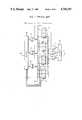
- FIG. 1 is a schematic circuit diagram of the conventional serial-parallel A/D converter
- FIG. 2 is a timing chart showing the timing of operations in the circuit of FIG. 1;
- FIG. 3 is a circuit diagram of a chopper-type comparator
- FIG. 4 is a circuit diagram of a serial-parallel A/D converter according to an embodiment of the present invention.
- FIG. 5 is a timing chart showing the timing of operations in the circuit of FIG. 4;
- FIGS. 6-8 circuit diagrams illustrating circuit examples of comparators used in the A/D converter of FIG. 4;
- FIG. 9 is a circuit diagram of a serial-parallel A/D converter according to another embodiment of the present invention.
- FIG. 10 is a timing chart showing the timing of operations in the circuit of FIG. 9;
- FIG. 11 is a circuit diagram illustrating an example of the circuit of the comparator used in the A/D converter of FIG. 9;
- FIG. 12 is a circuit diagram showing an analog-to-digital (A/D) converter according to another embodiment of the present invention.
- FIG. 13 is a circuit diagram illustrating an A/D converter according to another embodiment of the present invention.
- FIG. 14 is a timing chart showing the timing of operations in the circuit of FIG. 13;
- FIG. 15 is a circuit diagram illustrating a comparator configured by use of a clocked inverter
- FIG. 16 is a timing chart showing the timing of operations in a case where the comparator of FIG. 15 is applied to the circuit of FIG. 4;
- FIG. 17 is a circuit diagram illustrating a comparator in which the inputs and outputs of two inverters commonly connected to a switch MOS transistor are crosswise wired to form a latch circuit;
- FIG. 18 is a circuit diagram depicting a circuitry in which the comparators of FIGS. 15-17 are connected in parallel;
- FIGS. 19A-19B are configuration examples showing a case where the comparator of FIG. 15 is combined with digital logic circuits
- FIG. 20 is a circuit diagram illustrating an example in which MOS transistors are added to the circuit configuration of FIGS. 19A-19B to increase the operation speed;
- FIG. 21 is a circuit diagram showing an example in which the control means of the MOS transistors of the comparator circuit is changed
- FIG. 22 is a circuit diagram depicting an example of a comparator implemented by adding MOS transistors to the comparator of FIG. 20;
- FIG. 23 is a circuit diagram illustrating an example of another circuit configuration of the comparator.
- FIG. 24 is a circuit diagram showing a circuit example in which the comparator of FIG. 23 is partially modified.
- FIG. 25 is a circuit diagram depicting another circuit example in which the comparator of FIG. 23 is partially modified.
- a 2 n -bit parallel A/D comparator necessitates 2 2n -1 comparators.
- a serial-parallel converter constituted from an upper stage and a lower stage can be implemented by use of 2 n+1 -2 comparators.
- the number of stages however is not limited to two. Since the size of the circuit of the serial-parallel converter can be minimized, the area required for the circuit and the power dissipation can be greatly reduced as compared with the parallel converter.
- FIG. 1 shows an example of circuit configuration of the conventional serial-parallel A/D converter which is also called sub-range A/D converter.
- the digital signal is assumed to comprise four bits and the A/D conversion is to be accomplished through two stages for the two high-order bits and two low-order bits, respectively.
- three divided voltage values V R1 , V R2 , and V R3 between an input voltage V in and reference voltage values V RH and V RL are simultaneously compared by use of three comparators 10.
- An encoder 16 converts the compare result into a 2-bit digital signal to determine two high-order bits D u (coarse conversion).
- the D u indicates one of four partitions to which the input analog signal belongs.
- each partition must be further divided into for sub-partitions.
- the encoder 16 Based on the two high-order bits indicating the compare result, the encoder 16 outputs a signal SEL for selecting one of four switches 12-15.
- the selected switch circuit selectively supplies a fine division voltage to a low-order comparator.
- the input voltage V in is also being supplied to three low-order comparators 11 and is compared therein with each division voltage from a switch selected by use of the signal SEL. From the compare result, an encoder 17 determines two low-order bits D L .
- FIG. 3 shows an example of a chopper comparator
- FIG. 2 is a timing chart of the A/D converter.
- An operation of the chopper comparator is effected through an autozero cycle and a compare cycle.
- the inputs and outputs of inverters 30 and 31 are short-circuited by switches 32 and 33, respectively so as to automatically set the inverters to a zero point which is at an intermediate point between a high level and a low level, and at the same time, turns a switch 34 on to apply the input voltage V in to a capacitor C36, which is in turn charged up to the V in .
- the switches 32 and 33 are turned off to set the inverters 30 and 31 to the high amplification state, thereby turning the switch 35 on to apply the reference voltage V R to the capacitor C36.
- the difference voltage between V in and V R becomes the input signal, which is amplified by two stages of inverters 30-31 coupled in the sense of the alternate current, and an output Q from the inverter 31 of the final stage is stored in a latch 37.
- the high-order and low-order comparators 10-11 receive the input voltage V in .
- the high-order comparator 10 receives the predetermined reference voltage V R during the compare cycle of the high-order bit D u (in which the COARSE pulse is at the high level), whereas the low-order comparator 11 receives the reference voltage V R during the compare cycle of the low-order bit D L (in which the FINE pulse is at the high level); thereafter the comparators 10-11 each perform the voltage comparison between V R and V in .
- all bits of the digital data of V in are outputted after the comparison result of the low-order bit D L is obtained, namely, during a period in which the DATA pulse is at the high level.
- the circuit size and power dissipation can be reduced by adopting the serial-parallel converter, the conversion speed in lowered.
- the conversion speed has been required to be improved.
- FIGS. 4-6 show an embodiment of the present invention in which FIG. 4 depicts a circuit diagram, FIG. 5 illustrates a timing chart, and FIG. 6 demonstrates a configuration example of the comparator of FIG. 4.
- the input voltage V in is determined to be at which one of 16 levels between the reference voltage values V RH and V RL .
- FIG. 4 is a circuit diagram illustrating the circuit configuration of the serial-parallel A/D converter according to the present invention. For simplicity, a 4-bit configuration will be described.
- the input voltage V in is simultaneously compared with three division voltage values divided by use of resistors.
- the compare result is encoded by the encoder 16 into the two high-order bits D u .
- the encoder 16 Based on the compare result from the comparators 10, the encoder 16 outputs a signal SEL for selecting one of four switches 12-15.
- the SEL signal is used to select some of the finely divided voltage values, and the selected voltage values are applied to the proper reference voltage terminals of the low-order comparators 11a-11b.
- the input voltage V in is simultaneously compared with the selected division voltage value.
- the encoder 17 encodes the compare result into the two low-order bits D L .
- the high-order and low-order bits D u and D L are combined to form a digital output.
- the subsequent operation of the high-order comparators cannot be started until the operation of the low-order comparators is finished. This is because the high-order and low-order comparators receive inputs at the same time. If the next input is received to initiate converting the high-order bits before the operation of the low-order comparators is finished, the low-order comparators cannot receive the next input.
- To set the operation of the low-order comparators in the wait state means that the conversion speed is low as described in conjunction with FIGS. 1-3. If a plurality of sets of low-order comparators are provided for operation in a preset sequence, the A/D conversion of the subsequent input signal can be started before the operation of the low-order comparators is completed.
- the comparators of FIG. 4 each can keep a data input; for example, a chopper comparator of FIG. 6 may be used.
- the group of switches need only have a function to transfer a digital output from the comparator 11a or 11b to the encoder 17, namely, a multiplexer comprising logic gates is applicable.
- the circuit configuration and operation of the comparator of FIG. 6 are similar to those of the chopper comparator of FIG. 3; however, the latch circuit 38 includes a combination of two clocked inverters 39 (controlled by a clock signal) and an inverter 40 and operates in synchronism with the comparator so as to store the output therefrom.
- the latch circuit has a simple circuit configuration and is thus suitable for an integrated circuit.
- FIG. 5 shows the operation timing of the serial-parallel A/D converter of FIG. 4.
- the high-order comparators 10 perform an autozero operation according to an autozero signal AZ(U), and at the same time, effect a storing or sampling of the input voltage V in .
- a low-order comparators 11a perform an autozero operation and a data sampling in reply to a first autozero signal and achieve a compare operation in response to a first low-order bit compare signal LOWER(a). For LOWER(a), the high-order comparators have already received the next data.
- low-order comparators 11b then execute an autozero operation and a sampling in response to a second autozero signal AZ(Lb), and the compare operation is achieved according to a second low-order bit compare signal LOWER(b). At this point, the next data items are already stored in the high-order comparator 10a and the low-order comparator 11a. These two sets of low-order comparators 11a and 11b alternately operate with opposite phases.
- FIG. 7 shows another example of a comparator to be used in the serial-parallel A/D converter of FIG. 4.
- This circuit performs an operation similar to the operation of the chopper comparator of FIG. 6.
- a latch circuit 41 comprises a clocked inverter 39, a storage capacitor C S , and an inverter 42.
- the storage capacitor C S may be formed only with a parasitic capacity including the gate capacity of the inverter 42.
- the latch circuit 41 has a simple circuit configuration and is suitable for an integrated circuit.
- FIG. 8 is a circuit example of a comparator used in the series-parallel A/D converter of FIG. 4 in which the comparator comprises a differential amplifier.
- the input voltage V IN and the reference voltage V R received by the switches 34 and 35, respectively are sampled and held by capacitors C S , C S at the input terminals of the differential amplifier 43, and then the difference voltage V IN -V R is amplified and outputted.
- the output data is stored in a latch circuit comprising a composite logic gate.
- Two complementary outputs from the differential amplifier 43 are further amplified by the positive-feedback loop of the latch circuit 44, which makes at possible to obtain a sufficiently stable logic output.
- the comparators each have a function to sample and to hold an input signal. Comparators not having the data hold function may be used together with a sample-and-hold circuit S/H provided for each set of comparators.
- FIG. 9 shows a circuit diagram of the serial-parallel A/D converter according to another embodiment of the present invention.
- a set of high-order comparators 10 and two sets of low-order comparators 11a-11b each are provided with a sample-and-hold circuit.
- a sample-and-hold circuit S/H(U) is commonly linked to the input ports of three high-order comparators 10, whereas a sample-and-hold circuit S/H(La) 21 and a sample-and-hold circuit S/H(Lb) 22 are commonly linked to the input terminals of a set of three low-order comparators 11a and a set of three low-order comparators 11b, respectively, so that the input voltage V in is subjected to a sample-and-hold operation and then is supplied to each comparator.
- the sample-and-hold circuits S/H (La) 21 and SH (Lb) 22 for the low-order bits alternately operate in synchronism with the sample-and-hold circuit SH(U)20 for the high-order bits. That is, the sample-and-hold circuit SH(La) 21 samples the input voltage V in while the sample-and-hold signal S/H(La) is at the high level and holds the input voltage V in while the sample-and-hold signal S/H(La) is at the low level. Similarly, the sample-and-hold circuit S/H (Lb) 22 effects a sample-and-hold operation on the input voltage V in according to the sample-and-hold signal S/H (Lb).
- the input voltage V in sampled by the sample-and-hold circuit 21 for the low-order bits is compared with a reference voltage selected while the signal LOWERa is at the high level (a), and the data D La of the low-order bits is outputted while the signal DATA is at the high level (shadowed portion a).
- the input voltage V in sampled by the sample-and-hold circuit 22 is compared with a reference voltage selected while the signal LOWERb is at the high level (b), and the data D Lb of the low-order bits is outputted while the signal DATA is at the high level (shadowed portion b).
- FIG. 11 shows a circuit example of a comparator not having the data hold function to be used in the serial-parallel A/D converter of FIG. 9. Since sample-and-hold circuits 20 - 22 are provided, the comparator can be configured with an ordinary differential amplifier 45 without necessitating the sample-and-hold function. The output from the differential amplifier 45 is stored in a latch 44 comprising logic gates. The comparator can be constructed with simple circuits requiring only one control clock and hence this circuit configuration is suitable for an integrated circuit.
- FIG. 12 shows an analog-to-digital converter according to another embodiment of the present invention.
- This circuit configuration comprises an increased number of comparators for the conversion of low-order bits so that the conversion of high-order bits and the conversion of low-order bits are concurrently achieved in some portions.
- the other features are similar to those of the embodiment of FIG. 4.
- one of the select switch circuits 12-15 is selected.
- the switch circuits are used to select three divided voltages, however, these switches select seven divided voltages associated with three low-order bits in this embodiment. Namely, the voltage ranges each selected by the respective switch circuits are overlapped at the end portions thereof.
- the voltage ranges for the low-order bit conversion is extended with respect to the lower and upper limits of each range, even if there exists a slight mismatch between the conversion circuit for the high-order bits and the conversion circuit for the low-order bits, the correct conversion result can be obtained.
- the switch circuit 13 has been mistakenly selected in place of switch circuit 14 due to the insufficient accuracy of the high-order comparators 10.
- the conversion of the low-order bits is not so meaningful in the circuit of FIG. 4.
- the present invention even in this case, if the input voltage V in is in the extended voltage range, the comparison between the reference voltage and the input voltage V in is effectively conducted and hence the digital conversion value can be correctly extracted.
- the low-order data D' L which should comprise two bits may include three bits due to an overflow.
- the overflow bit need only be carried up to the high-order bits D u , which is simply achievable by a logic circuit 50.
- the comparators 10 have mistakenly selected the group of switches 14 in place of the group of switches 13. Also, in this case, if the input voltage V in is in the extended voltage range, the comparison of V in with the reference voltage is effectively accomplished to correctly obtain the digital conversion value.
- the digital conversion value D can be obtained by simply effecting an addition or a subtraction between the high-order two-bit data D u and the low-order three-bit data D' L .
- the method for generating the correct four bits from the combination of the configuration of three low-order bits and the two high-order bits is not restricted by this procedure.
- the mismatching between the circuit operations for converting the high-order and low-order bits can be prevented in the serial-parallel A/D converter, and a highly-accurate A/D converter capable of effecting an A/D conversion without a malfunction can be implemented in an integrated circuit.
- FIG. 13 shows an A/D converter including two sets of comparators 10a and 10b for converting the high-order bits and four sets of comparators 11a, 11b, 11c, and 11d for converting the low-order bits.
- Each comparator has the data hold function.
- the multiplexers 52 and 54 sequentially receive data into the encoders 16 and 18, respectively so as to generate a digital output.
- FIG. 14 is the timing chart of the circuit of FIG. 13.
- Two sets of comparators 10a-10b for the high-order bits alternately operate to convert the upper bits of the input signal (UPPER(a) UPPER(b)).
- the set of comparators 10a receives an input
- the set of comparators 11a or 11b for the low-order bits simultaneously receives an input.
- Two sets of comparators 11a and 11b for the low-order bits alternately operate for the same comparator set 10a (AZ(La), LOWER(a); AZ(Lb), LOWER(b)). This is the same as for the set of comparators 10 for the high-order bits and the sets of comparators 11a-11b for the low-order bits shown in FIG. 4.
- this circuit configuration performs an operation equivalent to the operation accomplished when two units of the circuits of FIG. 4 are operated with a phase difference therebetween.
- the components such as the divider resistors and encoders can be naturally shared; consequently, the operation speed can be increased and the number of parts can be minimized.
- each comparator is desired to accomplish a compare operation with a current the magnitute of which is as small as possible. Taking other aspects also into consideration, a MOS comparator is quite favorable which operates with a low power dissipation and which is suitable for an integrated circuit.
- a differential-type comparator is configured by use of a pair of clocked inverters to block the constant-current path, thereby minimizing the power dissipation.
- Two input voltages are subjected to the sample-and-hold operation at the input terminals of the clocked inverters, which are then activated; and then the difference voltage therebetween is amplified through a positive feedback loop and the compare result is outputted.
- FIG. 15 is a circuit diagram of a comparator including clocked inverters.
- the inputs and outputs of two clocked CMOS inverter,s 60 and 70 are respectively connected to form a latch.
- an input voltage V x is applied via a switch SW x .
- an input voltage V y is applied via a switch SW y .
- the comparator operation is performed according to the timing chart of FIG. 16.
- the switches SW x and SW y are turned on, the input voltages V x and V y are respectively supplied.
- the potential of the nodes Q 1 and Q 2 changes to V y and V x , respectively.
- a clock ⁇ turns the MOS transistors 62-63 on and an inverse clock ⁇ simultaneously turns the MOS transistors 64-65 on, which then activates the clocked inverters 60-70 to operate the positive feedback loop depending on the relationships between V x and V y , thereby determining the latch state.
- Q 1 and Q 2 are at the low and high levels, respectively for V x >V y and are at the high and low levels respectively for V x ⁇ V y .
- the result obtained by comparing V x with V y is outputted to the node Q 1 or Q 2 .
- the output may be obtained from P 1 , P 2 , P 3 , or P 4 .
- the difference output can be obtained through branches on the right and left sides of the diagram.
- This comparator has no path for a constant current and thus any current thereof is a transient current for charging or discharging, which makes it possible to reduce the power dissipation.
- This configuration is therefore suitable when a multiplicity of comparators are arranged in an apparatus such a series-parallel A/D converter.
- FIG. 16 shows a timing chart applied when the comparator of FIG. 15 is used in the circuit of FIG. 4.
- the comparators 10 for the high-order bits the input and reference signals are received while the clock is "1" (a in SWX, SWY), and then the conversion is achieved (a in ⁇ ).
- a comparator for the low-order bits 11a in FIG. 4
- the comparator for the high-order bits receive data (a in SWX, SWY)
- the data is simultaneously extracted (a in SWX); and after the CLOCK is set to the low level
- the reference signal is received (a in SWY) and then the comparison is effected (a in ⁇ ).
- the input signal is received when the CLOCK is set to the low level (b in SWX) and the reference signal is received when the CLOCK is set to the high level (b in SWY), and then the compare operation is executed (b in ⁇ ).
- the output data is supplied after the respective compare operation is completed.
- the two inverters 60-70 each include four MOS transistors connected in series.
- the switch transistors controlling the clock signal need not necessarily be disposed for the respective inverters.
- FIG. 17 is a circuit diagram of a comparator in which the inputs and outputs of two inverters sharing a switch MOS transistor are crosswise connected to form a latch configuration.
- the inputs and outputs of the CMOS inverters 70-71 are respectively connected to form a latch circuit and the nodes 72-73 are connected to the power source lines V SS and V DD , respectively through the clocked MOS switches 74 and 75, respectively, the switches 74-75 being controlled to be set to ON/OFF by the clock signals ⁇ and ⁇ , respectively.
- the input voltage V x is applied to the input of the inverter 70 via the switch SW x and the (reference) voltage V Y is applied to the input of the inverter 71 via the SW Y .
- the operation of the circuit of FIG. 17 is completely the same as that of the circuit of FIG. 15.
- FIG. 18 is a schematic circuit diagram in which the comparators of FIGS. 15 and 17 are connected in parallel.
- the compare result from each comparator 80 is encoded by an encoder 81 to generate a digital value D out comprising a predetermined number n of bits. Due to the low power dissipation of the comparator 80, even if the number of comparators to be connected in parallel is increased, for example, 256 comparators are integrated for an 8-bit configuration, the power dissipation will rarely become a problem.
- FIGS. 19A-19B show configuration examples in which the comparators of FIG. 15 are combine with digital logic circuits.
- a comparator 95 has outputs P 1 , P 1 , P 2 , and P 2 which are directly connected to input terminals D and D of a D-type flip-flop 92 and input terminals d and d of digital logic circuits 93-94, respectively.
- an RS flip-flop 96 comprising NAND gates is connected to the output terminals P 1 and P 1 of the comparator 95 and an RS flip-flop 97 including NOR gates is connected to the output terminals P 2 and P 2 thereof.
- the output terminals P 1 and P 2 output the different voltage levels, which then determine the state of the RS flip-flop 96 and the predetermined outputs are delivered from the output terminals Q 1 and Q 1 .
- the output terminals P 1 and P 1 hold the previous states or are set to the high level (V DD ).
- V DD the inputs of the NAND gates constituting the RS flip-flop
- the RS flip-flop 96 outputs the compare result from the comparator 95 in a stable fashion. This is also the case with the RS flip-flop 97 connected to the output terminals P 2 and P 2 .
- FIG. 20 shows a circuit example configured by adding MOS transistors to the circuit configuration of FIGS. 19A-19B to improve the operation speed.
- PMOS's 110-111 and NMOS's 112-113 are respectively connected in parallel and are controlled to be set to ON/OFF according to the clocks ⁇ and ⁇ . If two input voltages are beforehand applied to input terminals Q and Q, the clocks ⁇ and ⁇ are set to the low and high levels, respectively.
- the PMOS's 110-111 are then turned on and the nodes P 1 and P 1 are biased with a voltage V DD , which causes the NMOS's 112-113 to turn on and thus the nodes P 2 and P 2 are biased with a voltage V SS .
- the bias speed is sufficiently high because the PMOS's 110-111 and NMOS's 112-113 are rapidly turned on by the clocks ⁇ and ⁇ .
- FIG. 21 shows a circuit example in which the control means of the MOS transistors 110-113 of the comparator circuit shown in FIG. 20 is changed.
- the voltages at P 2 and P 2 are directly applied to the gates of the PMOS transistors 110-111, respectively; whereas the voltages at P 1 and P 1 are directly applied to the gates of the NMOS transistors 112-113. If the two input voltages are beforehand applied to the input terminals Q-Q, the voltage remaining at P 1 and P 1 are at a level sufficient enough to turn the NMOS's 112-113 on, while the voltages remaining at P 2 -P 2 are at a level sufficient to turn the PMOS's 110-111 on regardless of the previous compare results.
- This positive feedback enables a high-speed initial reset operation to set the respective sections to the initial voltages.
- FIG. 22 shows an example of a comparator implemented by adding MOS transistors between P 1 and P 2 and between P 1 and P 2 , respectively.
- An NMOS comparator 130 is connected between P 1 and P 2
- an NMOS comparator 131 is linked between P 1 and P 2 .
- These comparators are controlled to be set to ON/OFF by the clocks ⁇ and ⁇ ; namely, during the initial reset period after the input voltages are applied, these comparators are set to OFF. During the compare period following the initial reset period, these comparators are turned on to make the paths between P 1 and P 2 and between P 1 and P 2 conductive, which helps increasing the operation speed of the positive feedback loop comprising the clocked inverters 60 and 70.
- a PMOS gate may be used in place of the NMOS gate, or the NMOS and PMOS gates may be utilized in the same circuit configuration.
- the outputs may also be extracted from the nodes P 2 and P 2 .
- FIG. 23 shows another circuit diagram of a comparator in which the NMOS gates 130-131 are removed from the clocked inverters 60-70, respectively of FIG. 22 to p 1 to P 2 and P 1 to P 2 , then the NMOS gates 112-113 for setting the initial voltages are removed, and the V n line 140 can be changed over between a voltage V DD (high potential) and a voltage T GND (low potential) by use of a PMOS gate 141 and an NMOS gate 142.
- ⁇ 0 , ⁇ , and ⁇ are set to the high, high, and low levels, respectively, the V N line is connected to the power voltage V GND , the PMOS gates 110-111 turn off, the PMOS gates 64-65 and NMOS gates 62-63 turn on, and then a positive feedback loop for rapidly amplifying the difference between the input voltages V x and V y operates and hence the compare results are outputted to W and W. Since the transient current flows only during a slight period of time, namely, the initial reset period and the compare period, the power dissipation is sufficiently minimized. In addition, the positive feedback operation makes it possible to achieve a high-speed compare operation.
- FIG. 24 shows a circuit example implemented by partially modifying the comparator of FIG. 23.
- the voltage V N 140 and the voltage V M obtained by inverting V N through a CMOS inverter 150 are used in place of the clocks ⁇ and ⁇ , respectively.
- FIG. 25 is another circuit example in which the comparator of FIG. 23 is partially modified.
- the PMOS gates 110-111 of the circuit of FIG. 23 are removed and a PMOS gate 151 is utilized in place thereof to set the initial voltages at P 1 and P 1 to the same potential.
- the initial potential is set to the power voltage V DD by use of four MOS gates M1-M4. Althrough the ON/OFF states of the four MOS gates M1-M4 are determined by the levels of the input voltages V x and V y , at least two MOS gates are on in an ordinary case, which enables the initial voltage to be set.
Abstract
Description
output Q=Low level for V.sub.in >V.sub.R and
output Q=High level for V.sub.in <V.sub.R.
Claims (12)
Applications Claiming Priority (4)
| Application Number | Priority Date | Filing Date | Title |
|---|---|---|---|
| JP60-210012 | 1985-09-25 | ||
| JP60-210013 | 1985-09-25 | ||
| JP21001285A JPS6271321A (en) | 1985-09-25 | 1985-09-25 | Comparator |
| JP60210013A JPH0761017B2 (en) | 1985-09-25 | 1985-09-25 | A / D converter |
Publications (1)
| Publication Number | Publication Date |
|---|---|
| US4745393A true US4745393A (en) | 1988-05-17 |
Family
ID=26517808
Family Applications (1)
| Application Number | Title | Priority Date | Filing Date |
|---|---|---|---|
| US06/911,154 Expired - Lifetime US4745393A (en) | 1985-09-25 | 1986-09-24 | Analog-to-digital converter |
Country Status (1)
| Country | Link |
|---|---|
| US (1) | US4745393A (en) |
Cited By (38)
| Publication number | Priority date | Publication date | Assignee | Title |
|---|---|---|---|---|
| DE3902313A1 (en) * | 1988-01-27 | 1989-08-03 | Sony Corp | ANALOG / DIGITAL CONVERTER |
| US4893124A (en) * | 1987-03-04 | 1990-01-09 | Kabushiki Kaisha Toshiba | Pipelined serial-parallel A/D converter |
| US4939518A (en) * | 1987-09-24 | 1990-07-03 | Hitachi, Ltd. | Analog to digital converter |
| EP0383151A1 (en) * | 1989-02-13 | 1990-08-22 | National Semiconductor Corporation | Multistep flash analog to digital converter with voltage estimator |
| US4968990A (en) * | 1988-05-19 | 1990-11-06 | Samsung Electronics Co., Ltd. | Analog-to-digital converter with all parallel BiCMOS |
| US4999631A (en) * | 1988-07-01 | 1991-03-12 | Kabushiki Kaisha Toshiba | High-precision and high-speed analog/digital converter having low power consumption |
| US5019821A (en) * | 1988-12-08 | 1991-05-28 | Kabushiki Kaisha Toshiba | Bias circuit for a subranging analog to digital converter |
| US5019820A (en) * | 1988-08-29 | 1991-05-28 | Matsushita Electric Industrial Co., Ltd. | Serial-parallel type A/D converter having reference resistor chain and current source array |
| US5049882A (en) * | 1990-12-20 | 1991-09-17 | Burr-Brown Corporation | High speed analog-to-digital converter |
| US5093664A (en) * | 1989-10-02 | 1992-03-03 | Minister Of Post, Telecommunications And Space French State, Center National D'etudes Des Communication | High-speed half-flash type analog/digital converter |
| US5099240A (en) * | 1990-09-17 | 1992-03-24 | Motorola Inc. | Subranging adc with error correction through increased fine step span and noise reducing layout |
| US5134400A (en) * | 1991-01-07 | 1992-07-28 | Harris Corporation | Microwave multiplying D/A converter |
| US5138318A (en) * | 1989-10-16 | 1992-08-11 | Matsushita Electric Industrial Co., Ltd. | Differential voltage buffer amplifier circuit and serial-parallel A-D converter |
| US5138319A (en) * | 1990-08-30 | 1992-08-11 | Harris Corporation | Two stage a/d converter utilizing dual multiplexed converters with a common converter |
| US5140326A (en) * | 1991-01-29 | 1992-08-18 | Harris Corporation | Converter comparator cell with improved resolution |
| US5151700A (en) * | 1989-08-04 | 1992-09-29 | Matsushita Electric Industrial Co., Ltd. | Serial-parallel type a/d converter |
| US5231399A (en) * | 1991-09-27 | 1993-07-27 | Trw Inc. | Differential quantizer reference resistor ladder for use with an analog-to-digital converter |
| US5237326A (en) * | 1989-02-02 | 1993-08-17 | Samsung Electronics Co., Ltd. | Flash type analog-to-digital converter having MOS comparators |
| US5247301A (en) * | 1990-09-20 | 1993-09-21 | Hitachi, Ltd. | Analog-to-digital conversion method and apparatus with a controlled switch for high-speed conversion |
| EP0570099A2 (en) * | 1992-05-14 | 1993-11-18 | Advanced Micro Devices, Inc. | Apparatus for generating a digital signal output representative of a received analog signal |
| EP0604168A1 (en) * | 1992-12-19 | 1994-06-29 | Mms Space Systems Limited | Cascadable flash analog-digital converters |
| US5345234A (en) * | 1993-08-31 | 1994-09-06 | Advanced Micro Devices Inc. | Method and apparatus for combining a flash analog to digital converter with digital to analog functions |
| US5554989A (en) * | 1993-08-06 | 1996-09-10 | Mitsubishi Denki Kabushiki Kaisha | A/D converter having folded arrangement of voltage comparator |
| US5726653A (en) * | 1996-01-22 | 1998-03-10 | Industrial Technology Research Institute | Tri-step analog-to-digital converter |
| US5736948A (en) * | 1995-03-20 | 1998-04-07 | Hitachi, Ltd. | Semiconductor integrated circuit device and control system |
| US6566916B1 (en) * | 2001-11-20 | 2003-05-20 | Oki Electric Industry Co., Ltd. | Chopper type comparator |
| US20030112169A1 (en) * | 2001-12-17 | 2003-06-19 | Fujitsu Limited | A/D converter with reduced power consumption |
| US6608503B2 (en) | 2001-08-10 | 2003-08-19 | Shakti Systems, Inc. | Hybrid comparator and method |
| EP1349283A2 (en) * | 2002-03-29 | 2003-10-01 | Fujitsu Limited | A/D converter circuit |
| EP1367719A2 (en) * | 2002-05-30 | 2003-12-03 | Fujitsu Limited | AD converter circuit and AD conversion method |
| US20040189505A1 (en) * | 2003-03-25 | 2004-09-30 | Rohm Co., Ltd. | Analog-to-digital converter |
| US20060044023A1 (en) * | 2004-08-25 | 2006-03-02 | Jae-Cheol Yun | Integrated circuit comparators and devices that compensate for reference voltage fluctuations |
| US20060114140A1 (en) * | 2004-11-29 | 2006-06-01 | Taiwan Semiconductor Manufacturing Co., Ltd. | Two step flash analog to digital converter |
| US20080062733A1 (en) * | 2006-09-12 | 2008-03-13 | Michael John Gay | Dc-dc converter and method |
| EP1940031A3 (en) * | 2003-10-21 | 2008-11-05 | Fujitsu Limited | A/D conversion circuit |
| DE19946750B4 (en) * | 1998-09-30 | 2012-11-22 | National Semiconductor Corp.(N.D.Ges.D.Staates Delaware) | Two-step analog-to-digital converter and method |
| US8384578B2 (en) * | 2011-07-13 | 2013-02-26 | Imec | Stochastic analog-to-digital (A/D) converter and method for using the same |
| US10573359B2 (en) | 2012-02-13 | 2020-02-25 | Tadao Nakamura | Marching memory, a bidirectional marching memory, a complex marching memory and a computer system, without the memory bottleneck |
Citations (3)
| Publication number | Priority date | Publication date | Assignee | Title |
|---|---|---|---|---|
| GB2082410A (en) * | 1980-08-23 | 1982-03-03 | Plessey Co Ltd | Analogue-to-digital converter |
| US4417233A (en) * | 1979-02-28 | 1983-11-22 | Matsushita Electric Industrial Co., Ltd. | Fully parallel threshold type analog-to-digital converter |
| US4612531A (en) * | 1985-02-12 | 1986-09-16 | Rca Corporation | Intermeshed resistor network for analog to digital conversion |
-
1986
- 1986-09-24 US US06/911,154 patent/US4745393A/en not_active Expired - Lifetime
Patent Citations (3)
| Publication number | Priority date | Publication date | Assignee | Title |
|---|---|---|---|---|
| US4417233A (en) * | 1979-02-28 | 1983-11-22 | Matsushita Electric Industrial Co., Ltd. | Fully parallel threshold type analog-to-digital converter |
| GB2082410A (en) * | 1980-08-23 | 1982-03-03 | Plessey Co Ltd | Analogue-to-digital converter |
| US4612531A (en) * | 1985-02-12 | 1986-09-16 | Rca Corporation | Intermeshed resistor network for analog to digital conversion |
Cited By (54)
| Publication number | Priority date | Publication date | Assignee | Title |
|---|---|---|---|---|
| US4893124A (en) * | 1987-03-04 | 1990-01-09 | Kabushiki Kaisha Toshiba | Pipelined serial-parallel A/D converter |
| US4939518A (en) * | 1987-09-24 | 1990-07-03 | Hitachi, Ltd. | Analog to digital converter |
| DE3902313C3 (en) * | 1988-01-27 | 2003-07-24 | Sony Corp | Analog / digital converter |
| DE3902313A1 (en) * | 1988-01-27 | 1989-08-03 | Sony Corp | ANALOG / DIGITAL CONVERTER |
| US4968990A (en) * | 1988-05-19 | 1990-11-06 | Samsung Electronics Co., Ltd. | Analog-to-digital converter with all parallel BiCMOS |
| US4999631A (en) * | 1988-07-01 | 1991-03-12 | Kabushiki Kaisha Toshiba | High-precision and high-speed analog/digital converter having low power consumption |
| US5019820A (en) * | 1988-08-29 | 1991-05-28 | Matsushita Electric Industrial Co., Ltd. | Serial-parallel type A/D converter having reference resistor chain and current source array |
| US5019821A (en) * | 1988-12-08 | 1991-05-28 | Kabushiki Kaisha Toshiba | Bias circuit for a subranging analog to digital converter |
| US5237326A (en) * | 1989-02-02 | 1993-08-17 | Samsung Electronics Co., Ltd. | Flash type analog-to-digital converter having MOS comparators |
| EP0383151A1 (en) * | 1989-02-13 | 1990-08-22 | National Semiconductor Corporation | Multistep flash analog to digital converter with voltage estimator |
| US5151700A (en) * | 1989-08-04 | 1992-09-29 | Matsushita Electric Industrial Co., Ltd. | Serial-parallel type a/d converter |
| US5093664A (en) * | 1989-10-02 | 1992-03-03 | Minister Of Post, Telecommunications And Space French State, Center National D'etudes Des Communication | High-speed half-flash type analog/digital converter |
| US5138318A (en) * | 1989-10-16 | 1992-08-11 | Matsushita Electric Industrial Co., Ltd. | Differential voltage buffer amplifier circuit and serial-parallel A-D converter |
| US5138319A (en) * | 1990-08-30 | 1992-08-11 | Harris Corporation | Two stage a/d converter utilizing dual multiplexed converters with a common converter |
| US5099240A (en) * | 1990-09-17 | 1992-03-24 | Motorola Inc. | Subranging adc with error correction through increased fine step span and noise reducing layout |
| US5247301A (en) * | 1990-09-20 | 1993-09-21 | Hitachi, Ltd. | Analog-to-digital conversion method and apparatus with a controlled switch for high-speed conversion |
| US5049882A (en) * | 1990-12-20 | 1991-09-17 | Burr-Brown Corporation | High speed analog-to-digital converter |
| US5134400A (en) * | 1991-01-07 | 1992-07-28 | Harris Corporation | Microwave multiplying D/A converter |
| US5140326A (en) * | 1991-01-29 | 1992-08-18 | Harris Corporation | Converter comparator cell with improved resolution |
| US5231399A (en) * | 1991-09-27 | 1993-07-27 | Trw Inc. | Differential quantizer reference resistor ladder for use with an analog-to-digital converter |
| EP0570099A2 (en) * | 1992-05-14 | 1993-11-18 | Advanced Micro Devices, Inc. | Apparatus for generating a digital signal output representative of a received analog signal |
| EP0570099A3 (en) * | 1992-05-14 | 1994-09-07 | Advanced Micro Devices Inc | Apparatus for generating a digital signal output representative of a received analog signal |
| US5296858A (en) * | 1992-05-14 | 1994-03-22 | Advanced Micro Devices, Inc. | Improved two-stage analog-to-digital converter |
| EP0604168A1 (en) * | 1992-12-19 | 1994-06-29 | Mms Space Systems Limited | Cascadable flash analog-digital converters |
| US5554989A (en) * | 1993-08-06 | 1996-09-10 | Mitsubishi Denki Kabushiki Kaisha | A/D converter having folded arrangement of voltage comparator |
| US5345234A (en) * | 1993-08-31 | 1994-09-06 | Advanced Micro Devices Inc. | Method and apparatus for combining a flash analog to digital converter with digital to analog functions |
| US5736948A (en) * | 1995-03-20 | 1998-04-07 | Hitachi, Ltd. | Semiconductor integrated circuit device and control system |
| US5726653A (en) * | 1996-01-22 | 1998-03-10 | Industrial Technology Research Institute | Tri-step analog-to-digital converter |
| DE19946750B4 (en) * | 1998-09-30 | 2012-11-22 | National Semiconductor Corp.(N.D.Ges.D.Staates Delaware) | Two-step analog-to-digital converter and method |
| US6608503B2 (en) | 2001-08-10 | 2003-08-19 | Shakti Systems, Inc. | Hybrid comparator and method |
| US6566916B1 (en) * | 2001-11-20 | 2003-05-20 | Oki Electric Industry Co., Ltd. | Chopper type comparator |
| US6888488B2 (en) * | 2001-12-17 | 2005-05-03 | Fujitsu Limited | A/D converter with reduced power consumption |
| US20030112169A1 (en) * | 2001-12-17 | 2003-06-19 | Fujitsu Limited | A/D converter with reduced power consumption |
| EP1349283A2 (en) * | 2002-03-29 | 2003-10-01 | Fujitsu Limited | A/D converter circuit |
| CN1326329C (en) * | 2002-03-29 | 2007-07-11 | 富士通株式会社 | A/d converter circuit |
| EP1349283A3 (en) * | 2002-03-29 | 2004-05-06 | Fujitsu Limited | A/D converter circuit |
| EP1367719A3 (en) * | 2002-05-30 | 2004-05-06 | Fujitsu Limited | AD converter circuit and AD conversion method |
| US20030222806A1 (en) * | 2002-05-30 | 2003-12-04 | Fujitsu Limited | AD converter circuit and AD conversion method |
| EP1367719A2 (en) * | 2002-05-30 | 2003-12-03 | Fujitsu Limited | AD converter circuit and AD conversion method |
| US6836237B2 (en) * | 2003-03-25 | 2004-12-28 | Rohm Co., Ltd. | Analog-to-digital converter |
| US20040189505A1 (en) * | 2003-03-25 | 2004-09-30 | Rohm Co., Ltd. | Analog-to-digital converter |
| US7760125B2 (en) | 2003-10-21 | 2010-07-20 | Fujitsu Microelectronics Limited | A/D conversion circuit for use with low-potential and high-potential power supplies |
| EP1940031A3 (en) * | 2003-10-21 | 2008-11-05 | Fujitsu Limited | A/D conversion circuit |
| US20090015450A1 (en) * | 2003-10-21 | 2009-01-15 | Fujitsu Limited | D/a conversion circuit and a/d conversion circuit |
| US20100225512A1 (en) * | 2003-10-21 | 2010-09-09 | Fujitsu Semiconductor Limited | A/d conversion circuit for use with low-potential and high-potential power supplies |
| US7876253B2 (en) | 2003-10-21 | 2011-01-25 | Fujitsu Semiconductor Limited | A/D conversion circuit for use with low-potential and high-potential power supplies |
| US20060044023A1 (en) * | 2004-08-25 | 2006-03-02 | Jae-Cheol Yun | Integrated circuit comparators and devices that compensate for reference voltage fluctuations |
| US20060114140A1 (en) * | 2004-11-29 | 2006-06-01 | Taiwan Semiconductor Manufacturing Co., Ltd. | Two step flash analog to digital converter |
| US20080062733A1 (en) * | 2006-09-12 | 2008-03-13 | Michael John Gay | Dc-dc converter and method |
| US7439716B2 (en) * | 2006-09-12 | 2008-10-21 | Semiconductor Components Industries, L.L.C. | DC-DC converter and method |
| TWI406489B (en) * | 2006-09-12 | 2013-08-21 | Semiconductor Components Ind | Dc-dc converter and method |
| US8384578B2 (en) * | 2011-07-13 | 2013-02-26 | Imec | Stochastic analog-to-digital (A/D) converter and method for using the same |
| US10573359B2 (en) | 2012-02-13 | 2020-02-25 | Tadao Nakamura | Marching memory, a bidirectional marching memory, a complex marching memory and a computer system, without the memory bottleneck |
| US11164612B2 (en) | 2012-02-13 | 2021-11-02 | Tadao Nakamura | Marching memory, a bidirectional marching memory, a complex marching memory and a computer system, without the memory bottleneck |
Similar Documents
| Publication | Publication Date | Title |
|---|---|---|
| US4745393A (en) | Analog-to-digital converter | |
| US7265705B1 (en) | Opamp and capacitor sharing scheme for low-power pipeline ADC | |
| US4893124A (en) | Pipelined serial-parallel A/D converter | |
| US7324038B2 (en) | Subranging analog to digital converter with multi-phase clock timing | |
| EP0976198B1 (en) | A method and device to convert an analog current to a digital signal | |
| US7443333B2 (en) | Single stage cyclic analog to digital converter with variable resolution | |
| KR0173858B1 (en) | Analog-to digital conversion method and apparatus with a controlled switch for high-speed conversion | |
| US9473163B1 (en) | Preamplifier circuit and SAR ADC using the same | |
| JP2006517765A (en) | Automatic zeroing in critical continuous time applications | |
| US20160112058A1 (en) | Ad converter | |
| US6031480A (en) | Method and apparatus for implementing a pipelined A/D converter with inter-stage amplifiers having no common mode feedback circuitry | |
| JPH10285037A (en) | Analog to digital converter circuit | |
| US7791523B2 (en) | Two-step sub-ranging analog-to-digital converter and method for performing two-step sub-ranging in an analog-to-digital converter | |
| US7154423B2 (en) | Successive approximation A/D converter comparing analog input voltage to reference voltages and a comparator for use therein | |
| US4667180A (en) | Continuous time domain analog-digital converter | |
| US5684485A (en) | Multi-comparison analog-to-digital converters using the interpolation principle | |
| JPH0681048B2 (en) | A / D converter | |
| US6927723B2 (en) | A/D converter and A/D conversion method | |
| US6700523B2 (en) | Analog to digital converter selecting reference voltages in accordance with feedback from prior stages | |
| JPS6271336A (en) | Analog-digital converter | |
| WO2008109107A1 (en) | Charge-domain pipelined charge-redistribution analog-to-digital converter | |
| JPH0212416B2 (en) | ||
| US20230155603A1 (en) | Ad converter | |
| JP3630796B2 (en) | Switched capacitor arithmetic circuit | |
| JP2775805B2 (en) | A / D conversion circuit composed of CMOS |
Legal Events
| Date | Code | Title | Description |
|---|---|---|---|
| AS | Assignment |
Owner name: HITACHI, LTD., 6, KANDA SURUGADAI 4-CHOME, CHIYODA Free format text: ASSIGNMENT OF ASSIGNORS INTEREST.;ASSIGNORS:TSUKADA, TOSHIRO;UEDA, SEIICHI;MATSUURA, TATSUJI;AND OTHERS;REEL/FRAME:004608/0577 Effective date: 19860916 Owner name: HITACHI VLSI ENGINEERING CORPORATION, 1448, JOUSUI Free format text: ASSIGNMENT OF ASSIGNORS INTEREST.;ASSIGNORS:TSUKADA, TOSHIRO;UEDA, SEIICHI;MATSUURA, TATSUJI;AND OTHERS;REEL/FRAME:004608/0577 Effective date: 19860916 Owner name: HITACHI, LTD., 6, KANDA SURUGADAI 4-CHOME, CHIYODA Free format text: ASSIGNMENT OF ASSIGNORS INTEREST;ASSIGNORS:TSUKADA, TOSHIRO;UEDA, SEIICHI;MATSUURA, TATSUJI;AND OTHERS;REEL/FRAME:004608/0577 Effective date: 19860916 Owner name: HITACHI VLSI ENGINEERING CORPORATION, 1448, JOUSUI Free format text: ASSIGNMENT OF ASSIGNORS INTEREST;ASSIGNORS:TSUKADA, TOSHIRO;UEDA, SEIICHI;MATSUURA, TATSUJI;AND OTHERS;REEL/FRAME:004608/0577 Effective date: 19860916 |
|
| STCF | Information on status: patent grant |
Free format text: PATENTED CASE |
|
| FPAY | Fee payment |
Year of fee payment: 4 |
|
| FPAY | Fee payment |
Year of fee payment: 8 |
|
| FEPP | Fee payment procedure |
Free format text: PAYOR NUMBER ASSIGNED (ORIGINAL EVENT CODE: ASPN); ENTITY STATUS OF PATENT OWNER: LARGE ENTITY |
|
| FPAY | Fee payment |
Year of fee payment: 12 |