US4754255A - User identifying vehicle control and security device - Google Patents
User identifying vehicle control and security device Download PDFInfo
- Publication number
- US4754255A US4754255A US07/050,319 US5031987A US4754255A US 4754255 A US4754255 A US 4754255A US 5031987 A US5031987 A US 5031987A US 4754255 A US4754255 A US 4754255A
- Authority
- US
- United States
- Prior art keywords
- vehicle
- transmitter
- signal
- valid
- intrusion
- Prior art date
- Legal status (The legal status is an assumption and is not a legal conclusion. Google has not performed a legal analysis and makes no representation as to the accuracy of the status listed.)
- Expired - Fee Related
Links
- 230000006870 function Effects 0.000 claims abstract description 17
- 238000000034 method Methods 0.000 claims abstract description 12
- 230000004044 response Effects 0.000 claims abstract description 10
- 238000013479 data entry Methods 0.000 claims abstract description 9
- 238000012545 processing Methods 0.000 claims abstract description 6
- 230000005540 biological transmission Effects 0.000 claims description 8
- 230000033001 locomotion Effects 0.000 claims description 8
- 230000008569 process Effects 0.000 claims description 7
- 239000011521 glass Substances 0.000 claims description 4
- 230000002401 inhibitory effect Effects 0.000 claims 2
- 238000001514 detection method Methods 0.000 claims 1
- 230000008054 signal transmission Effects 0.000 claims 1
- 230000000881 depressing effect Effects 0.000 description 10
- 238000010586 diagram Methods 0.000 description 10
- 230000000994 depressogenic effect Effects 0.000 description 9
- 238000012544 monitoring process Methods 0.000 description 5
- 230000035939 shock Effects 0.000 description 4
- 230000008901 benefit Effects 0.000 description 3
- 230000004397 blinking Effects 0.000 description 3
- 230000009545 invasion Effects 0.000 description 3
- 239000011159 matrix material Substances 0.000 description 3
- 230000002093 peripheral effect Effects 0.000 description 3
- 238000003491 array Methods 0.000 description 2
- 230000001413 cellular effect Effects 0.000 description 2
- 238000004891 communication Methods 0.000 description 2
- 239000007858 starting material Substances 0.000 description 2
- 229930091051 Arenine Natural products 0.000 description 1
- 230000001684 chronic effect Effects 0.000 description 1
- 230000001010 compromised effect Effects 0.000 description 1
- 230000003750 conditioning effect Effects 0.000 description 1
- 230000001186 cumulative effect Effects 0.000 description 1
- 230000004069 differentiation Effects 0.000 description 1
- 230000000694 effects Effects 0.000 description 1
- 239000000284 extract Substances 0.000 description 1
- 125000000524 functional group Chemical group 0.000 description 1
- 230000010354 integration Effects 0.000 description 1
- 230000006386 memory function Effects 0.000 description 1
- 230000001172 regenerating effect Effects 0.000 description 1
- 239000004065 semiconductor Substances 0.000 description 1
- 230000003068 static effect Effects 0.000 description 1
- 230000001702 transmitter Effects 0.000 description 1
- 230000001960 triggered effect Effects 0.000 description 1
Images


Classifications
-
- B—PERFORMING OPERATIONS; TRANSPORTING
- B60—VEHICLES IN GENERAL
- B60R—VEHICLES, VEHICLE FITTINGS, OR VEHICLE PARTS, NOT OTHERWISE PROVIDED FOR
- B60R25/00—Fittings or systems for preventing or indicating unauthorised use or theft of vehicles
- B60R25/01—Fittings or systems for preventing or indicating unauthorised use or theft of vehicles operating on vehicle systems or fittings, e.g. on doors, seats or windscreens
- B60R25/04—Fittings or systems for preventing or indicating unauthorised use or theft of vehicles operating on vehicle systems or fittings, e.g. on doors, seats or windscreens operating on the propulsion system, e.g. engine or drive motor
- B60R25/045—Fittings or systems for preventing or indicating unauthorised use or theft of vehicles operating on vehicle systems or fittings, e.g. on doors, seats or windscreens operating on the propulsion system, e.g. engine or drive motor by limiting or cutting the electrical supply to the propulsion unit
-
- B—PERFORMING OPERATIONS; TRANSPORTING
- B60—VEHICLES IN GENERAL
- B60R—VEHICLES, VEHICLE FITTINGS, OR VEHICLE PARTS, NOT OTHERWISE PROVIDED FOR
- B60R25/00—Fittings or systems for preventing or indicating unauthorised use or theft of vehicles
- B60R25/20—Means to switch the anti-theft system on or off
- B60R25/24—Means to switch the anti-theft system on or off using electronic identifiers containing a code not memorised by the user
-
- B—PERFORMING OPERATIONS; TRANSPORTING
- B60—VEHICLES IN GENERAL
- B60R—VEHICLES, VEHICLE FITTINGS, OR VEHICLE PARTS, NOT OTHERWISE PROVIDED FOR
- B60R25/00—Fittings or systems for preventing or indicating unauthorised use or theft of vehicles
- B60R25/01—Fittings or systems for preventing or indicating unauthorised use or theft of vehicles operating on vehicle systems or fittings, e.g. on doors, seats or windscreens
- B60R25/04—Fittings or systems for preventing or indicating unauthorised use or theft of vehicles operating on vehicle systems or fittings, e.g. on doors, seats or windscreens operating on the propulsion system, e.g. engine or drive motor
-
- B—PERFORMING OPERATIONS; TRANSPORTING
- B60—VEHICLES IN GENERAL
- B60R—VEHICLES, VEHICLE FITTINGS, OR VEHICLE PARTS, NOT OTHERWISE PROVIDED FOR
- B60R25/00—Fittings or systems for preventing or indicating unauthorised use or theft of vehicles
- B60R25/10—Fittings or systems for preventing or indicating unauthorised use or theft of vehicles actuating a signalling device
- B60R25/1003—Alarm systems characterised by arm or disarm features
-
- B—PERFORMING OPERATIONS; TRANSPORTING
- B60—VEHICLES IN GENERAL
- B60R—VEHICLES, VEHICLE FITTINGS, OR VEHICLE PARTS, NOT OTHERWISE PROVIDED FOR
- B60R25/00—Fittings or systems for preventing or indicating unauthorised use or theft of vehicles
- B60R25/10—Fittings or systems for preventing or indicating unauthorised use or theft of vehicles actuating a signalling device
- B60R25/1004—Alarm systems characterised by the type of sensor, e.g. current sensing means
-
- B—PERFORMING OPERATIONS; TRANSPORTING
- B60—VEHICLES IN GENERAL
- B60R—VEHICLES, VEHICLE FITTINGS, OR VEHICLE PARTS, NOT OTHERWISE PROVIDED FOR
- B60R25/00—Fittings or systems for preventing or indicating unauthorised use or theft of vehicles
- B60R25/20—Means to switch the anti-theft system on or off
- B60R25/2009—Antitheft state indicator
-
- B—PERFORMING OPERATIONS; TRANSPORTING
- B60—VEHICLES IN GENERAL
- B60R—VEHICLES, VEHICLE FITTINGS, OR VEHICLE PARTS, NOT OTHERWISE PROVIDED FOR
- B60R25/00—Fittings or systems for preventing or indicating unauthorised use or theft of vehicles
- B60R25/20—Means to switch the anti-theft system on or off
- B60R25/2081—Means to switch the anti-theft system on or off combined with personal settings of other vehicle devices, e.g. mirrors, seats, steering wheels
-
- B—PERFORMING OPERATIONS; TRANSPORTING
- B60—VEHICLES IN GENERAL
- B60R—VEHICLES, VEHICLE FITTINGS, OR VEHICLE PARTS, NOT OTHERWISE PROVIDED FOR
- B60R25/00—Fittings or systems for preventing or indicating unauthorised use or theft of vehicles
- B60R25/20—Means to switch the anti-theft system on or off
- B60R25/23—Means to switch the anti-theft system on or off using manual input of alphanumerical codes
-
- B—PERFORMING OPERATIONS; TRANSPORTING
- B60—VEHICLES IN GENERAL
- B60R—VEHICLES, VEHICLE FITTINGS, OR VEHICLE PARTS, NOT OTHERWISE PROVIDED FOR
- B60R25/00—Fittings or systems for preventing or indicating unauthorised use or theft of vehicles
- B60R25/20—Means to switch the anti-theft system on or off
- B60R25/24—Means to switch the anti-theft system on or off using electronic identifiers containing a code not memorised by the user
- B60R25/241—Means to switch the anti-theft system on or off using electronic identifiers containing a code not memorised by the user whereby access privileges are related to the identifiers
-
- G—PHYSICS
- G07—CHECKING-DEVICES
- G07C—TIME OR ATTENDANCE REGISTERS; REGISTERING OR INDICATING THE WORKING OF MACHINES; GENERATING RANDOM NUMBERS; VOTING OR LOTTERY APPARATUS; ARRANGEMENTS, SYSTEMS OR APPARATUS FOR CHECKING NOT PROVIDED FOR ELSEWHERE
- G07C9/00—Individual registration on entry or exit
- G07C9/00174—Electronically operated locks; Circuits therefor; Nonmechanical keys therefor, e.g. passive or active electrical keys or other data carriers without mechanical keys
- G07C9/00182—Electronically operated locks; Circuits therefor; Nonmechanical keys therefor, e.g. passive or active electrical keys or other data carriers without mechanical keys operated with unidirectional data transmission between data carrier and locks
- G07C2009/00206—Electronically operated locks; Circuits therefor; Nonmechanical keys therefor, e.g. passive or active electrical keys or other data carriers without mechanical keys operated with unidirectional data transmission between data carrier and locks the keyless data carrier being hand operated
- G07C2009/00222—Electronically operated locks; Circuits therefor; Nonmechanical keys therefor, e.g. passive or active electrical keys or other data carriers without mechanical keys operated with unidirectional data transmission between data carrier and locks the keyless data carrier being hand operated by more than one push button
-
- G—PHYSICS
- G07—CHECKING-DEVICES
- G07C—TIME OR ATTENDANCE REGISTERS; REGISTERING OR INDICATING THE WORKING OF MACHINES; GENERATING RANDOM NUMBERS; VOTING OR LOTTERY APPARATUS; ARRANGEMENTS, SYSTEMS OR APPARATUS FOR CHECKING NOT PROVIDED FOR ELSEWHERE
- G07C9/00—Individual registration on entry or exit
- G07C9/00174—Electronically operated locks; Circuits therefor; Nonmechanical keys therefor, e.g. passive or active electrical keys or other data carriers without mechanical keys
- G07C9/00182—Electronically operated locks; Circuits therefor; Nonmechanical keys therefor, e.g. passive or active electrical keys or other data carriers without mechanical keys operated with unidirectional data transmission between data carrier and locks
- G07C2009/00261—Electronically operated locks; Circuits therefor; Nonmechanical keys therefor, e.g. passive or active electrical keys or other data carriers without mechanical keys operated with unidirectional data transmission between data carrier and locks the keyless data carrier having more than one function
-
- G—PHYSICS
- G07—CHECKING-DEVICES
- G07C—TIME OR ATTENDANCE REGISTERS; REGISTERING OR INDICATING THE WORKING OF MACHINES; GENERATING RANDOM NUMBERS; VOTING OR LOTTERY APPARATUS; ARRANGEMENTS, SYSTEMS OR APPARATUS FOR CHECKING NOT PROVIDED FOR ELSEWHERE
- G07C9/00—Individual registration on entry or exit
- G07C9/00174—Electronically operated locks; Circuits therefor; Nonmechanical keys therefor, e.g. passive or active electrical keys or other data carriers without mechanical keys
- G07C2009/00753—Electronically operated locks; Circuits therefor; Nonmechanical keys therefor, e.g. passive or active electrical keys or other data carriers without mechanical keys operated by active electrical keys
- G07C2009/00769—Electronically operated locks; Circuits therefor; Nonmechanical keys therefor, e.g. passive or active electrical keys or other data carriers without mechanical keys operated by active electrical keys with data transmission performed by wireless means
-
- G—PHYSICS
- G07—CHECKING-DEVICES
- G07C—TIME OR ATTENDANCE REGISTERS; REGISTERING OR INDICATING THE WORKING OF MACHINES; GENERATING RANDOM NUMBERS; VOTING OR LOTTERY APPARATUS; ARRANGEMENTS, SYSTEMS OR APPARATUS FOR CHECKING NOT PROVIDED FOR ELSEWHERE
- G07C2209/00—Indexing scheme relating to groups G07C9/00 - G07C9/38
- G07C2209/04—Access control involving a hierarchy in access rights
Abstract
A vehicle control and/or access control and/or anti-theft system for motor vehicles including data entry apparatus designed to enter a predetermined signal, a decoder for processing the signal, apparatus to recognize which one of a plurality of valid signals was entered, and apparatus to control vehicle electrical functions in response to which valid signal was recognized. In the anti-theft system, operation of the vehicle is disabled by interrupting an essential vehicle circuit, and a method is provided together with the decoder for preventing the operation of the vehicle disabling system so that when the operator enters his specific signal the automobile can then be started and operated. In addition, the system monitors all points of entry into the vehicle, and also monitors various sensors for unusual disturbances. The system sounds a siren alarm and/or flashes the vehicle's interior lights, parking lights, and/or headlights, in the event of unauthorized entry or unusual disturbance. The system has the ability to differentiate between a plurality of authorized operators of the vehicle, and contains a logic processing device adapted to interface to automotive electrical functions such as memory devices programmed to adapt specific automotive functions to a plurality of operators. The system provides a diagnostics mode, enhanced exit supervision and a plurality of user-programmable features.
Description
This application is a continuation-in-part of our copending application Ser. No. 588,575 filed Mar. 12, 1984 now abandoned.
In recent years there has been a tremendous increase in the rate of automobile thefts and vandalism and theft from automobiles throughout the nation. Many different types of automobiles anti-theft systems have been designed and marketed. Early systems utilized a unique key-operated switch located on the vehicle's exterior to arm and disarm the system. These keyswitch controlled systems had many shortcomings, including the fact that the connecting wires of the key-switch itself could be bypassed by anyone with knowledge of the automobile system. In addition, the key could be stolen or easily duplicated and used by the thief himself.
Later systems sought to remedy the shortcomings of the earlier key-switch systems, by eliminating the key-switch itself. These "keyless" systems utilized various means to control arming and disarming, including switches hidden from plain view within the passenger compartment, the vehicle's own ignition switch, and digital keypads. However, these "keyless" systems also suffered from a significant shortcoming: if a door to the passenger compartment were opened, the alarm would only sound after an entry delay time, so as to allow the owner enough time to enter the passenger compartment and disarm the system. During this delay time, a thief could steal the stereo unit or other contents of the automobile, and furthermore damage the automobile or even defeat the alarm system, and steal the automobile.
Most recent systems attempt to remedy the entry delay shortcoming by employing remote control techniques. The vehicle owner utilizes a small transmitter to disarm the system from outside of the vehicle prior to entry. However, even these systems suffer the disadvantage of the earliest key-switch types: a lost or stolen transmitter could be used by the thief himself.
It is an object of the present invention to provide a vehicle control and/or anti-theft system which is highly effective and easy to use.
It is a further object of the invention to provide a new and novel vehicle anti-theft system providing more security than any system previously manufactured. This is accomplished by the use of a programmable owner input digital code system in which the code may be entered to disarm the system by remote control, so as to eliminate the need for any entry delay time. In addition, the system of this invention provides added optional convenience and security featuers heretofore unavailable. It is a further object to provide a new and special type of "user identification" which identifies which of several different legitimate operators is using the system, and thus the automobile, at any given time. The system can differentiate between several different legitimate operators and interface to a plurality of operator-specific memory controlled automotive functions such as driver's seat position, steering wheel tilt and telescope position, mirror position, radio station presets, climate control settings, maximum vehicle speed, cellular mobile telephone operation, phone number selections, etc.
It is still a further object of the invention to provide a diagnostics mode of operation which provides the means to evaluate the integrity of the system and its various peripheral components at any given time.
The operational characteristics of this invention are divided into two major functional groups: (1) security and system control functions, and (2) user identification functions, i.e. identification of, and differentiation between, several individuals who are each authorized to operate the vehicle. This application describes one possible embodiment of this invention. One of the components comprising this embodiment is a Keypad/Transmitter, which is slightly larger than a pocket watch and which may be attached to the operator's keychain if desired. The Keypad/Transmitter features twelve pushbuttons labeled with the numbers zero through nine, asterisk (*), and pound (#) symbol. The Keypad/Transmitter is used to broadcast a personal multi-digit code to disarm the system from outside of the vehicle prior to entry. In addition to, or as an alternative to the Keypad/Transmitter, several Single-Button Transmitters may also be utilized. Each of the single-button transmitters is encoded so as to broadcast a unique digital code whenever the transmitter's button is depressed.
As a back-up in the event that the Keypad/Transmitter or the Single-Button Transmitters are lost, a Keypad Command Center is mounted within the passenger compartment of the vehicle. The Keypad Command Center provides an array of pushbuttons similar to those of the Keypad/Transmitter, along with a plurality of indicator LEDs and a piezo element audio sounding device.
The integrity of the system of this invention is not compromised should a Keypad/Transmitter be lost or stolen. The Keypad/Transmitter can be used to disarm the system only if its owner's personal multi-digit code is entered correctly. The code may contain from as few as 3 to as many as 9 digits. In this manner, the remote digital system provides more than one billion possible codes from which the owner can choose. In addition, each system is factory-assigned to any one of a plurality of different digital channels. As a result, billions and billions of unique disarm codes are available.
Once the system has been armed by means of either the Keypad/Transmitter or an encoded single-button transmitter, a loud electronic siren alarm will be tripped instantly upon any unauthorized entry into or disturbance of the vehicle unless the system is first disarmed by the owner. Therefore, the vehicle and its contents are far more secure from theft than with less sophisticated, entry-delay-type alarms.
The system's Microprocessor or other logic processing device can be set up to decode a multiple number of codes, so that for instance there can be a master code for the "master operator", a separate code for a second operator, such as a spouse, and separate codes for other operators, such as employees, or even a temporary code for the mechanic. Only the "master operator" can program the system. That is, only the master code will allow the "master operator" to engage the programming mode, whereas the other user codes do not allow programming. Once the program mode has been engaged, the master operator may then establish (program) the other access codes, as well as alter the master code itself.
Upon entry of any of the valid access codes (upon either the Keypad/Transmitter or the Keypad Command Center), or receipt of the predetermined digital signal from any of the single-button transmitters, a binary output from the system's Microprocessor represents which of the valid codes was decoded, or which one of the Single-Button Transmitters was used. This is intended as an identification of the person operating the vehicle at that time. With that information, the system is capable of interfacing with and controlling things such as memory seat positions, mirror position, steering wheel tilt/telescope position, radio station presets, climate control settings, navigation control or speed control. The system can also control whether or not certain items will operate, such as a mobile telephone or an audio entertainment system, based upon which operator is using the vehicle at that time.
Another benefit of the unique Keypad/Transmitter is that multi-car families may protect all of their vehicles by installing an additional system in each of the other vehicles. They can then selectively disarm the system in any one vehicle so protected, with any one Keypad/Transmitter, simply by entering the specific multi-digit code for that vehicle and authorized operator.
The arming method of this invention categorizes it as a "passive" system. This means that if the system is not actively armed by the operator through the use of either the Keypad/Transmitter or one of the Single-Button Transmitters, the system will automatically arm itself after an exit delay time whenever the ignition key is turned off. The exit delay time allows the driver and passengers enough time to exit the vehicle and take with them any packages or belongings. The exit delay time may be set by the master operator from 10 to 120 seconds. If the system has been armed in this manner, and any of the doors to the passenger compartment is subsequently opened, the system will provide an entry delay time (instead of tripping the alarm siren instantly), to allow the authorized operator to disarm the system by entering his personal access code upon the Keypad Command Center. If the system is not disarmed prior to the expiration of the entry delay time, the system's alarm siren is then tripped. The entry delay time may be set by the master operator from 1 to 45 seconds. Unauthorized opening of the vehicle's engine compartment or luggage compartment will cause the system's alarm siren to be tripped instantly (without any entry delay) regardless of the method used to alarm the system.
If, after the system has been armed, it detects a disturbance to a sensor (sound, motion, impact, shock, etc.), the alarm siren will be tripped after a one second delay. However, if the system had been armed passively, rather than actively with a transmitter, and subsequently detects the opening of a passenger compartment door during the one second delay initiated by a disturbance to a sensor, the alarm siren will not be tripped at the end of the one-second delay. Instead, the entry delay is begun. This one-second delay is intended to prevent false alarms that might otherwise occur if a sensor responds, for example, to a key being inserted into the vehicle's door to unlock it upon normal entry.
In addition, a "valet mode" is provided to override the automatic passive arming feature to allow for extended loading and unloading, vehicle service, parking attendants, etc.
The automatic "passive" arming feature of this invention provides enhanced exit supervision in a manner that has heretofore never been accomplished in this field. This system allows a much shorter exit delay time than is now common, thereby providing greater security. It does this by monitoring the state of all trigger inputs in several protection "zones." These zones are the passenger compartment, the engine compartment, the trunk, and additional "sensor zones" for such devices as motion, impact, and/or glass breakage sensors. The system monitors all zones continuously. When the ignition key is turned off, the system automatically begins its passive arming process. If all of the zones are secure at that time, normal arming takes place. If all the zones are secure for the duration of the exit delay, the system will arm. If during the exit delay, any one of the zones become active (such as if a door is opened), the exit delay is temporarily suspended and reset to its maximum time value and when the vehicle is again secure, the exit delay begins again. In this way, the operator can remove the ignition key, open the door and exit from the car, leaving the door open to remove personal belongings from the car and the system will not activate until all doors are closed. The danger of this feature is that there could be a point of entry such as the hood, which if open (or if it "appeared" to the system to be open as the result of a pinched wire), would interrupt the passive arming cycle without the knowledge of the operator. If this were allowed to continue, the system would never arm.
The system of this invention solves this serious problem by continuously monitoring all protected zones many times per second. If any of the protected zones are not secure when the ignition key is turned off, that information is stored in the Microprocessor. The passive arming cycle proceeds with the exit delay "counting down," ignoring the unsecured zone. When the exit delay time lapses, the system would be allowed to arm and protect all zones other than the one that was not secured when the ignition key was turned off. If the unsecured zone becomes secure during the exit delay period, the Microprocessor automatically begins monitoring that zonen for supervised exit. If the unsecured zone becomes secure after the exit delay time has lapsed and the system has armed, the Microprocessor automatically begins monitoring that zone for unauthorized entry.
During the arming cycle, the red LED on the Keypad Command Center is on but blinks off once per second, and the Keypad Command Center's piezo element beeps once per second. If any door is opened, the piezo element stops beeping but the red LED continues to blink off at the once-per-second rate. If the door is then closed, the piezo starts beeping again, once per second during the arming cycle, then stops when the system is armed.
If there is an unsecured zone at the time the ignition key is turned off, the piezo element will beep 3 times per second (instead of once per second) to warn the operator that at least one zone will not be protected when the system arms. If the zone is subsequently secured during the exit delay time, the piezo will beep at its normal rate of once per second for the remainder of the exit delay time.
If the vehicle operator actively arms the system utilizing one of the transmitters, there is no entry delay or exit delay. If all zones are secure when the system receives the arming command broadcast from the transmitter, the alarm siren will "chirp" once and the vehicle's interior lights, parking and/or headlights will flash once as multiple acknowledgements that the system has armed and the vehicle is protected. However, if there is a zone that is not secure when the operator attempts to arm the system with a transmitter, the system will immediately arm and protect the secured zones, leaving the unsecured zone(s) unprotected. In this instance, upon receipt of the arming command broadcast from the transmitter, the alarm siren will "chirp" three times instead of the usual single chirp, and the vehicle's interior lights, parking and/or headlights will flash three times instead of their usual single flash. The operator can then return to the vehicle and check to see which zone is not secure, perhaps utilizing the system's diagnostics mode discussed in detail later.
As an extension of the system's ability to monitor the zones individually and continuously, if the alarm siren is tripped in response to unauthorized entry or disturbance, it will continue to sound for the specific time duration programed by the master operator. Once this time duration has lapsed, the alarm siren will stop sounding, unless a zone is not secure. In this instance, the alarm siren will continue to sound. If the alarm sounds for 8 minutes continuously, the zone causing it to sound is then ignored by the Microprocessor, allowing the system to reset (stop sounding the alarm) and continue monitoring the remaining zones for unauthorized entry. The ignored zone is not completely ignored, however. If it subsequently becomes secured, it will again be monitored for unauthorized entry.
This maximum alarm sounding time feature is handled somewhat differently with regard to sensors such as glass breakage detector, shock, vibration or motion sensors. Since the output response from these devices, when stimulated, is a short duration pulse, as opposed to the continuous trigger condition presented by an open door, the system will accumulate the overall length of time that the alarm sounds if tripped repeatedly by such sensors. When the cumulative time reaches a total of 8 minutes, the sensor zone responsible will then be ignored until the system is disarmed by the operator. The benefit of this feature is the minimization of chronic false alarms resulting from, for example, a motion sensor adjusted too sensitively which reacts unnecessarily to passing traffic.
Additional features of this invention include the following:
Ignition or starter bypass. The engine cannot be started unless the system is disarmed.
If, when the system is armed, it detects an attempt in progress to disarm the system by means of either random or sequential broadcast of digital data representing possible disarm codes, the alarm siren will be tripped if the attempt continues beyond a predetermined time limit.
As a back-up in the event that the Keypad/Transmitter or the Single-Button Transmitters are lost, an internally mounted keypad command center with a plurality of indicator LEDs and a piezo audio sounding device is provided. One LED flashes when the system is armed to provide notice to any thief that the car is protected by an alarm system. Other LEDs indicate the valet mode and program mode.
Outputs are provided to engage electromechanical actuators so as to lock and unlock the doors to the passenger compartment concurrent with remote control arming and disarming, respectively.
Additional outputs are provided to enable remote control functions such as trunk or rear hatch opening, garage door opening and closing, and engine starting, using the Keypad/Transmitter.
Automatic memory functions such as seat position settings, radio station presets and climate control settings can be preset for each user, and initiated remotely from the Keypad/Transmitter, any one of the Single-Button Transmitters, or other data entry means such as a vehicle mounted data entry device.
The nominal operating range of the system is approximately fifty feet in line of sight. No receiver antenna is required on the outside of the vehicle. The batteries used in the transmitters are commonly available batteries. The battery life is normally about one year.
The system's parameters programmed by the master operator are maintained virtually forever by a nonvolatile random access memory device such as one sold under the name "Novram", a trademark of XICOR Corp. No reserve battery is needed to maintain the memory. If the vehicle's battery is disconnected or becomes exhausted, all system parameters, plus the arm, disarm, or valet status of the system at the time of power loss, will be intact when power is restored to the system.
There are various two-button combinations that can be entered upon either the Keypad/Transmitter or the internally-mounted Keypad Command Center as commands to the system. These are, for instance, depressing buttons 5 and 8 simultaneously for a panic alarm which will instantly trip the alarm siren (from up to fifty feet away if initiated from the remote Keypad/Transmitter) regardless of the operating mode that the system is in. Depressing buttons 4 and 6 simultaneously is an auxiliary command which could be used to open the trunk. Depressing buttons 6 and 9 simultaneously is a second auxiliary command which could be used, for instance, for starting of the automobile. Depressing buttons 8 and 9 simultaneously could activate a separate garage door opener transmitter. The system is designed so that these particular commands can be initiated at any time from the internal keypad command center in the automobile. However, these 2-button commands, with the exception of the panic command, can only be initiated with the Keypad/Transmitter within 30 seconds after a valid access code is entered. This is a safety feature so that other Keypad/Transmitters on the same channel won't activate these particular commands.
The system is designed to provide additional two-button commands that can only be initiated from the Keypad Command Center within the passenger compartment. These commands are used to alter the system's operating characteristics. For example, depressing the numbers 8 and 0 simultaneously engages the diagnostics mode which provides a means of evaluating the integrity of the system and its peripheral components. Depressing buttons 2 and 4 simultaneously will allow a pager to be active even if the system is not armed. That is, if the operator carries a remote pager which signals when the alarm sounds, this command will enable the pager to respond to unauthorized entry or disturbances even if the siren itself does not sound. Thus, the pager reacts to all trigger inputs that would activate the alarm siren if armed. This is called the silent mode of operation and can be used, for instance, when parking in a hospital zone or if the operator is in a restaurant and wants to know if the vehicle is entered even though the alarm system is not armed.
An additional two-button command that can be used is, for instance, depressing numbers 2 and 6 simultaneously which causes the system to ignore any disturbances, such as noise, motion, impact, or ultrasonic, that might be detected by one or more of the sensors that comprise the system's sensor zones of protection. In this mode, the system will only monitor points of entry, such as passenger compartment doors, trunk and hood. This could be used for example when parking in a high noise or vibration area.
When the system's diagnostics mode is engaged (by simultaneously depressing the numbers 8 and 0 on the Keypad Command Center), the LEDs on the Keypad Command Center will display the status of the trigger input zones. The yellow LED, which is normally the valet mode indicator, will illuminate when the hood and/or trunk is open. The red LED, which is normally the arm/disarm status indicator, will illuminate when any door to the passenger compartment is open, and the green LED, normally the program mode indicator, will illuminate whenever any one of the sensors that comprise the sensor zones, such as the glass breakage detector, shock, vibration or motion sensor detects a disturbance. The operator can thus monitor how the system is operating and if there is an intrusion indication, which zone or zones of the system are causing the intrusion indication.
In the diagnostics mode, the Keypad Command Center's piezo element provides an audible indication of the performance of the transmitter and receiver sections of the system. The piezo element converts signals received by the system's receiver into an audio tone. Under normal conditions, if the system's receiver is functioning properly, and no transmitter is broadcasting, random background static will be heard from the Keypad Command Center's piezo element. If a button is depressed on a transmitter and an audio tone is heard from the Keypad Command Center's piezo element, then the system's transmitter is working properly; but if no audio tone is heard, either the system is not receiving the signal from the transmitter, or the transmitter itself is not functioning properly. In this way, using the diagnostics mode, the operator can evaluate how the system's transmitter and receiver are operating. The diagnostics mode can also be utilized so that all output devices of the system can be individually tested. For instance, depressing a predetermined button on the Keypad Command Center would cause the siren to sound, another button might cause the headlights to flash. In this manner all output aspects of the system may be evaluated for their operability.
If the system's alarm siren is tripped in response to unauthorized entry or unusual disturbance during the operator's absence, the system will inform the operator of this fact when he or she returns to the vehicle. This "attempted theft indication" is comprised of several elements:
1. The red status LED on the Keypad Command Center will be blinking rapidly rather than slowly, and
2. If the operator disarms the system by entering a disarm code upon the Keypad Command Center, the Keypad Command Center's piezo element will emit eight beeps in rapid succession, or
3. If the operator disarms the system using a transmitter, the alarm siren will issue a long blast, instead of the usual two "chirps," and the vehicle's interior lights and parking and/or headlights will flash on for one full second, instead of the usual two short flashes.
The red status LED on the internal keypad of the system gives several indications:
1. If it is on continuously, it is indicating that the system is disarmed;
2. If it is blinking on slowly, it is indicating that the system is armed;
3. If the inverse of (2) occurs, that is, if the red LED is blinking off slowly, it is indicating that the arming cycle is in progress;
4. If it is flashing rapidly, it is indicating that the alarm siren has been tripped during the operator's absence;
5. If it is off, either the Valet Mode or the Program Mode of the system is engaged. If the Valet Mode is engaged, the yellow LED will be illuminated. If the Program Mode is engaged, the green LED will be illuminated.
When the Program Mode is engaged, the "master operator" has the ability to program various operating characteristics or parameters of the system. There are a multiple number of programmable parameters of the system. For example, the following are nine programmable parameters:
1 through 4 are the four access codes available to the system, that is, the one master code and three additional subordinate access codes;
5. Whether or not the sensor zones are monitored;
6. Whether or not the siren chirps to acknowledge arm and disarm commands received from a transmitter. In an area such as a hospital zone, this could be turned off, leaving only the flashing of the vehicle's interior lights and parking and/or headlights as acknowledgements of remote arm/disarm commands;
7. The entry delay time can be programmed;
8. The exit delay time can be programmed. The entry delay time (7) and the exit delay time (8) are defaults, that is, they are time periods that the system provides only when the system is armed passively. When the system is armed actively using a transmitter, the entry delay time and exit delay time are not utilized.
9. The alarm sounding duration time can also be programmed.
Other objects and features of the invention will be described in reference to the drawings in which:
FIG. 1 is a block diagram showing the keypad/transmit ter of the present invention;
FIG. 2 is a block diagram showing the single-button transmitter;
FIG. 3 is a block diagram showing the remote communication elements of the present invention;
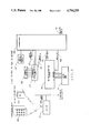
FIG. 4 is a block diagram showing the input-output system of the present invention;
FIG. 5 is a block diagram of the user identification system of the present invention.
Referring now to FIG. 1, there is shwon the block diagram of the Keypad/Transmitter. A battery 12 provides the power for the Keypad/Transmitter. The battery 12 is connected to a power switch 13 which operates as the power supply switch for the unit. The switch 13 is a transistor or other active semi-conductor device which receives a turn-on control signal whenever any button or buttons of the keypad 11 is (are) depressed. The keypad 11 of the Keypad/Transmitter is normally a simple one-of-twelve/common buss keypad. A diode matrix 14 encodes the depression of a specific button or buttons of the keypad 11 into specific binary coded data for processing by a serial data generator 15. The binary coded data from the diode matrix 14 is fed into a predetermined plurality of the address inputs of the serial data generator 15. Remaining address inputs of the serial data generator 15 comprise the channel assignment means 17. Each of the address inputs of the serial data generator 15 that comprise the channel assignment means 17 may be selectively connected to the positive side of the battery 12, or to the negative side of the battery 12, or left unconnected. The serial data generator 15 is compatible to the Keypad/Transmitter decoder 33 as shown on FIG. 3 and described later. The serial data generator 15 is designed to convert the binary coded data from diode matrix 14, and the data comprising the channel assignment, into a specific digital pulse train, unique to the keypad button or buttons depressed. Serial data generator 15 incorporates an oscillator which is used to establish the encoding and pulse train timing. This oscillator signal is also connected to a piezo disk 16 to produce an audible tone whenever a button or buttons of the keypad 11 is (are) depressed. A transmitter 18, for instance, is a high frequency colpits oscillator, or other similar oscillator configurations. It is activated by base bias established by the pulse train output generated by the serial data generator 15.
Referring now to FIG. 2, there is shown the single-button transmitter block diagram. The Single-Button Transmitter is powered by a battery 21 connected to a power switch 22. The switch is depressed by the operator to activate the single-button transmitter. A predetermined plurality of the address inputs of the serial data generator 25 are connected to the access code encoder 23, while the remaining address inputs of the serial data generator 25 are connected to the user identification assignment means 24. The access code encoder 23 and the user identification assignment means 24 are used to selectively connect each of the address inputs of the serial data generator 25 to either the positive side of the battery 21, or negative side of the battery 21, or left unconnected. The access code for all of the Single-Button Transmitters associated with a particular system, as determined by the access code encoder 23, will be the same, while the user identification assignment of each of the Single-Button Transmitters associated with a particular system, as determined by the user identification assignment means 24, will vary. Thus, a plurality of unique Single-Button Transmitters could be used to provide system access to a plurality of different operators, while each operator could be uniquely detected and identified by the system. The serial data generator 25 is compatible to the single-button transmitter decoder 34 as shown on FIG. 3 and described later. The serial data generator 25 is designed to convert the information represented by the configuration of the access code encoder 23, and the user identification assignment 24, into a specific serial digital pulse train, unique to that particular single-button transmitter. Serial data generator 25 incorporates an oscillator which is used to establish the encoding and pulse train timing. This oscillator signal is also connected to a piezo disk 26 to produce an audible tone whenever the power switch 22 is depressed. A transmitter 27, for instance, is a high frequency colpits oscillator, or other similar oscillator configurations. It is activated by base bias established by the pulse train output generated by the serial data generator 25.
Referring now to FIG. 3, there is shown a block diagram of the remote communications system of the invention. Keypad/Transmitters 30, of the type described in FIG. 1, and Single-Button Transmitters 31, of the type described in FIG. 2, are shown. A vehicle mounted data entry device 30A may also be used. When activated, the transmitter(s) 30 and/or 31 broadcast their signals on an infrared, RF, or other carrier to a Receiver 32. The Receiver 32 is adapted to receive the broadcast from both Keypad/Transmitters 30 and single-button transmitters 31. The Receiver 32 can, if it is an RF receiver, include a super regenerative amplifier and detector or other RF receiver which reproduces the transmitted pulse coded information. A signal conditioner and level shifter can be biased to greatly amplify the signal. Also, hysteresis can be provided to reduce the effects of background noise and increase range. The vehicle mounted data entry device 30A is connected directly to the Microprocessor 38.
When the Receiver 32 receives a broadcast signal, the serial digital data it extracts from the broadcast signal is simultaneously fed to Keypad/Transmitter decoder 33, to the single-button transmitter decoder 34, and to the diagnostics logic circuits, described later.
Address inputs of the Keypad/Transmitter Decoder 33 are connected to the channel assignment means 35. The channel assignment means 35 is used to configure the address inputs of the Keypad/Transmitter decoder 33 so as to match the configuration of the channel assignment means 17 (described in FIG. 1) of the Keypad/Transmitter 30. This is done to prevent the recognition of serial digital data from the Receiver 32 unless the data was broadcast from a Keypad/Transmitter whose channel assignment means 17 had been configured so as to match the configuration of the channel assignment means 35 of the Keypad/Transmitter Decoder 33.
When the Keypad/Transmitter decoder 33 processes matching-channel serial digital data from the Receiver 32, a valid transmission signal 36 is generated, along with binary coded Keypad/Transitter data 37 that is representative of the specific keypad button or buttons depressed on the Keypad/Transmitter. The valid transmission signal 36, and the binary coded Keypad/Transmitter data 37 is fed to a Microprocessor 38, which then processes the binary coded Keypad/Transmitter data 37 to determine which specific button or buttons of the Keypad/Transmitter was (were) depressed. The Microprocessor 38 continues to process data from the Keypad/Transmitter Decoder 33 to determine if a valid sequential multi-digit access code has been broadcast. A plurality of specific sequential multi-digit access codes used to operate the system may be programmed into the memory of the microprocessor 38 by the operator. Other logic processing devices such as gate arrays, programmable logic arrays, or transistor and integrated circuit logic can be used in place of a microprocessor.
The Microprocessor 38 can be programmed to cause the alarm to sound whenever a valid transmission signal 36 from the Keypad/Transmitter decoder 33 is present in excess of a predetermined anti-scan integration time (approximately 10 seconds). If a Keypad/Transmitter 30 were used to randomly broadcast different codes, in an attempt to determine the proper code sequence, and this attempt exceeded approximately 10 seconds in duration, the alarm would sound.
The Microprocessor 38 can also be programmed to provide a panic alarm which will cause the alarm to sound for whatever period of time is preset by the user or until reset. The panic alarm can be triggered, for example, by simultaneously depressing 2 predetermined Keypad/Transmitter buttons. The panic alarm can be set to sound even if a valid access code has been entered to disarm the system.
Single-button transmitter decoder 34 processes serial digital data from the Receiver 32 when the data is broadcast by a single-button transmitter 31. The access code data means 39 is used to configure a predetermined plurality of the address inputs of the Single-Button Transmitter Decoder 34 so as to match the configuration of the access code encoder 23 (described in FIG. 2) of the Single-Button Transmitter 31. This is done to prevent the recognition of serial digital data from the Receiver 32 unless the data was broadcast from a Single-Button Transmitter 31 whose access code encoder 23 had been configured so as to match the configuration of the access code data means 39 of the Single-Button Transmitter Decoder 34.
A user identification system is provided to identify which of the plurality of single-button transmitters 31 has activated the system, or which of a plurality of valid sequential multi-digit access codes has been entered upon either the Keypad/Transmitter 30 or the Keypad Command Center 44 (described in FIG. 4) located within the vehicle. This can be done, for example, by reserving the address inputs of the single-button transmitter decoder 34 that correspond to the address inputs comprising the user identification assignment means 24 of the serial data generator 25 (described in FIG. 2) of the single-button transmitter 31. The reserved address of the single-button Transmitter Decoder 34 comprise the user identification data 40. The address inputs of the single-button transmitter decoder 34 comprising the user identification data 40 are connected to the Microprocessor 38. The Microprocessor continuously cycles these addresses through all of the possible logical states.
When the Single-Button Transmitter Decoder 34 recognizes that a signal broadcast by a Single-Button Transmitter 31 matches both the preprogrammed addresses comprising the access code data 39 and one of the possible logic states of the addresses comprising the user ID data 39, a valid transmission signal 41 is generated by the Single-Button Transmitter Decoder 34 and sent to the Microprocessor 38. The Microprocessor 38 determines which one of the plurality of single-button transmitters has been activated, based upon the logic state of the address inputs of the Single-Button Transmitter Decoder 34 comprising the user ID data 40 at the time the match was detected. A serial digital data signal representing the particular Single-Button Transmitter, and thus the user identification, is generated by the Microprocessor 38 at its user ID output 42. Additionally, when a valid multidigit access code has been received from the Keypad/Transmitter 30 or keypad command center 44 (described in FIG. 4), the Microprocessor 38 generates a serial digital data signal at its user ID output 42 that represents the user member assigned by the operator to the specific multi-digit access code received.
Referring now to FIG. 4, there is shown the input-output block diagram of the invention. The serial digital data output from the Receiver 32 (described in FIG. 3) is fed into the diagnostics logic, LED and piezo driver circuitry 43. The Keypad Command Center 44 incorporates 3 LEDS (yellow 45, red 46, and green 47) and a piezo 48. Control signals for the 3 LEDs 45, 46, and 47 and the piezo 48 are also connected to the diagnostics logic, LED and piezo driver circuitry 43. The individual buttons 49 of the Keypad Command Center 44 comprise a simple one-of-twelve/common buss keypad. Signals from the one-of-twelve/common buss keypad 49 connect directly to the Microprocessor 38.
An input signal conditioner 50 connects trigger input signals, which signal the system when invasion of the system has occurred, to the Microprocessor 38. The trigger inputs include signals from the hood 51, the trunk 52, the sound and/or shock sensor(s) 53, the ignition 54, and door sensors 55 and 56. When the system is disarmed, either by a broadcast from the Keypad/Transmitter of one of the plurality of valid multi-digit access codes, or the broadcast from one of the plurality of encoded single-button transmitters, the vehicle's dome light illuminates for 30 seconds or until the ignition is turned on. This is done through the dome light relay 57, and provides a convenience for the operator.
These signals are fed to the Microprocessor which controls the output signal conditioning 58 to operate all the various peripheral components of the system. These components include the siren 59 if an invasion has occurred, a pulse circuit 60 to flash the vehicle's parking lights if an invasion has occurred, a silent paging transmitter 61, if desired; the release of the hood lock 62, door lock 63, door unlock 64, an engine interrupt relay 65, trunk release 66, an auxiliary for other functions 67, an external LED 68, and garage door opener control 69. Other functions, of course, can be programmed into the system.
Referring to FIG. 5, there is shown a block diagram of the invention's user identification system. The Microprocessor 38 monitors valid transmission signals 36 and 41 from the Keypad/Transmitter decoder 33 and the single-button transmitter decoder 34 (described in FIG. 3). Whenever a valid transmission signal 36 is recognized by the Microprocessor 38, or whenever a valid sequential multi-digit access code is entered (either upon the Keypad Command Center within the vehicle or upon the Keypad/Transmitter), a serial digital data signal from the user ID output 42 of the Microprocessor 38 is presented to a user ID decoder 70. There can also be a User, Data, Time, and Odometer Recorder 71 to record which one of the plurality of authorized operators used the automobile, along with the date, time, and vehicle odometer reading at that time. Additionally, at the time of determination of the specific user operating the system, a systems interface processor 72 can automatically control, through the automobile memory system:
the electronic entertainment systems 73;
the positions of the driver's seat, mirrors, and steering wheel 74;
the climate control 75;
the engine control such as maximum permissible speed 76;
as well as any other specific user identification function 77, such as a cellular phone.
The engine interrupt relay 65, of the present invention can be connected to various parts of the automobile such as the starter and/or the ignition system to disable the vehicle until such time as the system is disarmed by the operator. These various disabling methods are well known in prior vehicle alarm systems when utilized with a key or other single-button device as shown in U.S. Pat. Nos. 3,987,408 or 4,143,368. In addition, the various sensors for detecting intrusion into the vehicle placed in the doors, the trunk, the hood and including devices such as motion detectors or sound detector devices are also well known in the art.
As stated, the advantage of the device of the present invention is the use of a user-specific digital access code, which may be input from within the vehicle or broadcast by remote control. With the device of the present invention, an owner can use one Keypad/Transmitter to arm or disarm any number of automobiles within a group such as a family, each with a different keypad code and have in his possession only the one Keypad/Transmitter. In addition, each of the members of the family can have a separate access code identifiable by the system which can automatically control various automatic automobile functions such as seal position, mirror position, radio station preset control, etc. In addition, the Keypad/Transmitter allows the operator to broadcast a variety of signals to the system including signals to open the trunk, lock and/or unlock the doors, trip a panic alarm in the event of attack or assault, and even start the vehicle's engine by remote control if desired. These functions, as well as the entry and exit delay time, are all programmable through the Microprocessor, thus giving the operator control over his vehicle never before achieved.
Having thus described the invention, it is desired that the invention be limited only by the scope of the appended claims.
Claims (54)
1. A vehicle security system for a vehicle having an electrical system comprising, a transmitter designed to transmit a specially encoded predetermined digital signal, which constitutes a valid signal, a receiver for receiving the digital signal, means to determine whether the digital signal transmitted is one of a plurality of valid signals, means adapted to process valid signals, means to identify which one of the plurality of valid signals was received, means to control vehicle functions or system functions in response to which valid signal was received.
2. The device of claim 1 in which the transmitter comprises a keypad containing a plurality of individually labeled keys adapted to transmit a plurality of predetermined digital signals.
3. The device of claim 1 in which the transmitter comprises single button transmitter means containing means to differentiate among a plurality of single button transmitters, each from the other.
4. The device of claim 1 in which the transmitter comprises vehicle mounted data entry means adatped to enter specific encoded signals.
5. The device of claim 3 in which said means to differentiate among single button transmitters comprises user identification assignment means.
6. A vehicle security system for a vehicle having an electrical system comprising, a transmitter designed to transmit a specially encoded predetermined digital signal, which constitutes a valid signal, a receiver for receiving the digital signal, means to determine whether the digital signal transmitted is one of a plurality of valid signals, means adapted to process valid signals, means to identify which one of the plurality of valid signals was received, means connected to the vehicle electrical system to disable the vehicle by inhibiting an essential vehicle electrical circuit, means to prevent the operation of the vehicle disabling system, means to detect an intrusion into the vehicle, means to signal that an intrusion has occurred, and means to engage or arm the vehicle security system.
7. The device of claim 6 in which the transmitter comprises a keypad containing a plurality of individually labeled keys adapted to transmit a plurality of predetermined digital signals.
8. The device of claim 6 in which the transmitter comprises single button transmitter means containing means to differentiate among a plurality of single button transmitters, each from the other.
9. The device of claim 6 in which the transmitter comprises vehicle mounted data entry means adapted to enter specific encoded signals.
10. The device of claim 8 in which said means to differentiate among single button transmitters comprises user identification assignment means.
11. The device of claim 1 comprising recorder means to record pertinent data at the time of valid signal recognition.
12. The device of claim 11 in which said recorder means records at the time of valid signal recognition, the identity of the user, the date, time, location, and/or odometer reading of the vehicle.
13. The device of claim 6 comprising an alarm siren and means to activate said alarm siren upon detection of an intrusion.
14. The device of claim 13 comprising means to generate a plurality of audible siren chirps to indicate the arm to disarm or disarm to arm change of status of the system.
15. The device of claim 6 wherein the means to detect intrusions comprises a plurality of trigger means located at points of entry of the vehicle, and/or sensors adapted to detect sound, motion, vibration or glass breakage.
16. The device of claim 6 wherein the vehicle comprises a key activated ingition system, and entry doors, comprising means to automatically arm the system when the key has been turned to its off position, or removed from the ignition.
17. The device of claim 16 comprising an exit delay timer means adapted to delay the arming of the system for a predetermined exit delay time period after the last door of the vehicle has been closed.
18. The device of claim 17 comprising means to program the length of the exit delay time period.
19. The device of claim 17 comprising means to suspend the exit delay time period if any intrusion into the vehicle is detected prior to the expiration of the exit delay time period.
20. The device of claim 15 comprising means to continuously monitor all intrusion trigger means and store all intrusion occurances and means to notify the operator that an intrusion has occurred.
21. The device of claim 20 wherein the means to notify the operator of an intrusion comprises means to cause the siren alarm to sound a long blast upon entry of a valid disarm signal.
22. The device of claim 6 comprising a vehicle mounted keypad, said key pad comprising a plurality of light signal devices, one of which is adapted to glow constantly when the system is disarmed, flash slow-blinking-on when the system is armed, flash slow-blinking-off during the exit delay period and flash quickly when an intrusion has occurred.
23. The device of claim 22 wherein the means to notify the operator of an intrusion comprises an audio transducer located in the vehicle mounted keypad.
24. The device of claim 22 in which the vehicle mounted keypad comprises three LEDS, one to indicate the arm/disarm status, a second LED to indicate a valet mode, and a third LED to indicate a programming mode.
25. The device of claim 1 comprising means to conrol vehicle functions or vehicle accessory devices in response to which valid signal was recognized.
26. The device of claim 2 or 4 comprising means to open the trunk of the vehicle in response to recognition of a predetermined valid signal.
27. The device of claim 2 or 4 comprising means to lock and unlock the vehicle doors in response to recognition of predetermined valid signal.
28. The device of claim 2 or 4 comprising means to activate the alarm siren in response to recognition of a predetermined valid signal.
29. The device of claim 2 or 4 comprising anti-scan means adapted to activate an alarm siren whenever transmission of signals occurs in excess of a predetermined maximum time.
30. The device of claim 13 comprising means to reset the system and stop the alarm siren after a predetermined time period if no further intrusion is detected.
31. The device of claim 13 comprising means to flash the vehicle lights during the time the alarm siren is activated.
32. The device of claim 13 comprising means to silence the alarm but flash the vehicle lights to either indicate arm/disarm status or to indicate an intrusion.
33. The device of claim 1 comprising means to allow the operator to program features of the system.
34. The device of claim 33 in which said means to program the system comprises means to program: the disarm codes, whether or not specific trigger means are monitored, whether or not the alarm siren chirps to acknowledge arm and disarm commands, the entry and exit delay time periods and the alarm sounding duration time period.
35. The device of claim 33 where only one of the plurality of valid signals will permit programming of the system.
36. The device of claim 1 comprising means to override the selected parts of the system, and to place those parts in a non-operating state.
37. The device of claim 6 comprising means to automatically arm the system when the ignition key has been turned to its off position, or, in the alternative, to automatically arm the system from the remote transmitter.
38. The device of claim 15 comprising means to arm the system but ignore an unsecured trigger zone and monitor all remaining trigger zones.
39. The device of claim 1 or 6 comprising a non-volatile random access memory device adapted to retain the memory of all system parameters in the event power is disconnected or discharged.
40. The device of claim 22 comprising diagnostics mode means adapted to test the operability of a plurality of aspects of the system.
41. The device of claim 40 comprising an audio transducer device adapted to evaluate the quality of the transmitted signal received by the receiver from the transmitter.
42. The device of claim 40 comprising means to activate the LEDs to indicate which trigger zones show an intrusion.
43. An anti-theft vehicle security system for a vehicle having an electrical system comprising a radio frequency transmitter designed to transmit a series of predetermined digital pulses by modulating a predetermined RF carrier initiated by a remote keypad containing a plurality of individually labeled keys or a uniquely coded single button transmitter, a receiver for receiving the digital signals, a data decoder for decoding the transmitted pulses to determine any one of a plurality of valid transmissions which constitute a disarm code, a microprocessor adapted to receive a valid transmission signal, means to identify which one of a plurality of valid signals was transmitted, means connected to the vehicle electrical system to disable the vehicle by inhibiting an essential vehicle electrical ciruit, means to prevent the operation of the vehicle disabling system, means to detect an intrusion into the vehicle, means to signal that an intrusion has occurred.
44. The device of claim 43 wherein the vehicle comprises a key activated ignition system, comprising an exit time delay period means adapted to automatically arm the system at a predetermined time period after the ignition key is turned off.
45. The device of claim 44 comprising means to suspend the exit time delay period during any period in which an open door is detected during the exit time delay period.
46. The device of claim 43 in which the microprocessor scans the means to detect an intrusion continuously to determine whether an intrusion has occurred.
47. The device of claim 46 comprising means for the microprocessor to ignore a non-door intrusion if detected during the entry time delay period.
48. The device of claim 45 comprising means to terminate the automatic exit time delay period, by the use of the remote transmitter.
49. The device of claim 45 comprising an entry delay time period and means to ignore the entry delay time period as a result of arming the system by the use of the remote transmitter.
50. A vehicle control system for a vehicle having an electrical system and electrically controlled automotive functions comprising, a data entry means designed to transmit a specially encoded predetermined signal, a receiver for receiving the signal, means to determine whether the signal transmitted is one of a plurality of valid signals, a logic processing device adapted to receive valid signals, means to identify which one of a plurality of valid signals was transmitted, means connected to the vehicle electrical system to control the electrically controlled automotive functions in response to which one of the valid signals was received.
51. The device of claim 50 in which the transmitter comprises a keypad containing a plurality of individually labeled keys adapted to transmit a plurality of predetermined digital signals.
52. The device of claim 50 in which the transmitter comprises single button transmitter means containing means to differentiate among a plurality of single button transmitter, each from the other.
53. The device of claim 50 in which the transmitter comprises a vehicle mounted data entry means.
54. The device of claim 50 comprising recorder means to record pertinent vehicle data at the time of valid signal reception.
Priority Applications (8)
| Application Number | Priority Date | Filing Date | Title |
|---|---|---|---|
| US07/050,319 US4754255A (en) | 1984-03-12 | 1987-05-14 | User identifying vehicle control and security device |
| GB8725312A GB2204542B (en) | 1987-05-14 | 1987-10-29 | User identifying vehicle control and security device |
| KR1019870012868A KR940002682B1 (en) | 1987-05-14 | 1987-11-16 | User identifying vehicle control and security device |
| DE19873740638 DE3740638A1 (en) | 1987-05-14 | 1987-12-01 | VEHICLE CONTROL AND SAFETY DEVICE WITH OPERATOR IDENTIFICATION |
| FR878717582A FR2615152B1 (en) | 1987-05-14 | 1987-12-16 | VEHICLE CONTROL AND SECURITY DEVICE AND USER IDENTIFICATION |
| JP63021829A JPS63287644A (en) | 1987-05-14 | 1988-02-01 | Car safety device |
| CA000566683A CA1306042C (en) | 1987-05-14 | 1988-05-13 | User identifying vehicle control and security device |
| IT83384/88A IT1221835B (en) | 1987-05-14 | 1988-05-13 | SAFETY AND CONTROL DEVICE FOR VEHICLES THAT IDENTIFIES THE USER |
Applications Claiming Priority (2)
| Application Number | Priority Date | Filing Date | Title |
|---|---|---|---|
| US58857584A | 1984-03-12 | 1984-03-12 | |
| US07/050,319 US4754255A (en) | 1984-03-12 | 1987-05-14 | User identifying vehicle control and security device |
Related Parent Applications (1)
| Application Number | Title | Priority Date | Filing Date |
|---|---|---|---|
| US58857584A Continuation-In-Part | 1984-03-12 | 1984-03-12 |
Publications (1)
| Publication Number | Publication Date |
|---|---|
| US4754255A true US4754255A (en) | 1988-06-28 |
Family
ID=21964575
Family Applications (1)
| Application Number | Title | Priority Date | Filing Date |
|---|---|---|---|
| US07/050,319 Expired - Fee Related US4754255A (en) | 1984-03-12 | 1987-05-14 | User identifying vehicle control and security device |
Country Status (8)
| Country | Link |
|---|---|
| US (1) | US4754255A (en) |
| JP (1) | JPS63287644A (en) |
| KR (1) | KR940002682B1 (en) |
| CA (1) | CA1306042C (en) |
| DE (1) | DE3740638A1 (en) |
| FR (1) | FR2615152B1 (en) |
| GB (1) | GB2204542B (en) |
| IT (1) | IT1221835B (en) |
Cited By (343)
| Publication number | Priority date | Publication date | Assignee | Title |
|---|---|---|---|---|
| US4876649A (en) * | 1986-05-06 | 1989-10-24 | Aisin Seiki Kabushikikaisha | Harm preventing apparatus for vehicle |
| US4884055A (en) * | 1986-12-03 | 1989-11-28 | Delta Elettronica S.P.A. | Antitheft system |
| US4887064A (en) * | 1987-12-28 | 1989-12-12 | Clifford Electronics, Inc. | Multi-featured security system with self-diagnostic capability |
| US4888575A (en) * | 1986-12-31 | 1989-12-19 | Automobiles Peugeot | Device having a modifiable code for protecting against theft of automobile vehicles |
| US4914314A (en) * | 1986-06-16 | 1990-04-03 | Helmut Hirtz | Anti-theft device for motor vehicles using an electronic engine control |
| US4920338A (en) * | 1987-06-04 | 1990-04-24 | Nissan Motor Co., Ltd. | Automatic seat positioning device for automotive vehicle and the like |
| US4922224A (en) * | 1987-12-28 | 1990-05-01 | Clifford Electronics, Inc. | Electronic vehicle security system |
| US4928778A (en) * | 1987-12-09 | 1990-05-29 | Remote Automation & Control Electronics Inc. | Remote control car starter |
| US4931789A (en) * | 1983-11-01 | 1990-06-05 | Universal Photonix, Inc. | Apparatus and method for a universal electronic locking system |
| US4963856A (en) * | 1987-04-03 | 1990-10-16 | Mazda Motor Corporation | Theft deterrent system |
| US4963876A (en) * | 1989-08-21 | 1990-10-16 | Sanders Rudy T | Thin programmable remote control transmitter |
| EP0414121A2 (en) * | 1989-08-24 | 1991-02-27 | Blaupunkt-Werke GmbH | Car radio |
| US4997053A (en) * | 1990-02-15 | 1991-03-05 | Clifford Electronics, Inc. | Remote control vehicle seat and steering wheel positioning system |
| US5023591A (en) * | 1989-11-15 | 1991-06-11 | Allen V. Edwards | Anti-theft control apparatus |
| US5033000A (en) * | 1988-06-09 | 1991-07-16 | Natco Corporation | Variable keyed power distribution and control system for motorized wheelchair |
| US5049867A (en) * | 1988-11-30 | 1991-09-17 | Code-Alarm, Inc. | Vehicle security apparatus |
| US5081707A (en) * | 1989-08-08 | 1992-01-14 | Motorola, Inc. | Knowledge based radio |
| US5081667A (en) * | 1989-05-01 | 1992-01-14 | Clifford Electronics, Inc. | System for integrating a cellular telephone with a vehicle security system |
| EP0469333A1 (en) * | 1990-07-31 | 1992-02-05 | Dr.Ing.h.c. F. Porsche Aktiengesellschaft | Motor vehicle with a central locking device and an anti-theft alarm system |
| US5086868A (en) * | 1988-08-23 | 1992-02-11 | William G. Fontaine | Automotive protection system with a telescoping protective sleeve between brake pedal and brake actuator |
| WO1992002390A1 (en) * | 1990-07-31 | 1992-02-20 | Dr. Ing. H.C. F. Porsche Aktiengesellschaft | Motor vehicle with a central locking installation and a theft alarm system |
| US5113182A (en) * | 1990-01-19 | 1992-05-12 | Prince Corporation | Vehicle door locking system detecting that all doors are closed |
| US5132660A (en) * | 1991-01-09 | 1992-07-21 | Nutek Corporation | Vehicle security system |
| US5146215A (en) * | 1987-09-08 | 1992-09-08 | Clifford Electronics, Inc. | Electronically programmable remote control for vehicle security system |
| US5157375A (en) * | 1987-12-28 | 1992-10-20 | Clifford Electronics, Inc. | Electronic vehicle security system |
| US5172094A (en) * | 1991-12-02 | 1992-12-15 | Stadler David M | Automatically armed vehicle anti-theft system |
| WO1993001072A1 (en) * | 1991-07-03 | 1993-01-21 | Pierre Edmond Tuffet | Method and device for verifying the capacity of a driver to drive a vehicle |
| US5182551A (en) * | 1989-04-27 | 1993-01-26 | Matsushita Electric Industrial Co., Ltd. | Remote control system for audio/video devices |
| GB2264188A (en) * | 1992-02-12 | 1993-08-18 | Advance Security Inc | A portable vehicle burglar alarm device |
| US5243322A (en) * | 1991-10-18 | 1993-09-07 | Thompson Stephen S | Automobile security system |
| US5252965A (en) * | 1991-03-15 | 1993-10-12 | Delco Electronics Corporation | Changing one of many access codes upon removal of ignition key |
| US5252960A (en) * | 1991-08-26 | 1993-10-12 | Stanley Home Automation | Secure keyless entry system for automatic garage door operator |
| US5278452A (en) * | 1991-02-13 | 1994-01-11 | Koito Manufacturing Co., Ltd. | Lighting apparatus for vehicular discharge lamp |
| US5280267A (en) * | 1991-07-01 | 1994-01-18 | Medardo Reggiani | Passive action antitheft device |
| US5304812A (en) * | 1990-11-21 | 1994-04-19 | Sharp Kabushiki Kaisha | Optoelectronic device, information apparatus and data transmission system using optoelectronic device for simplifying wirings and reducing size, and method of controlling the optoelectronic device |
| US5307048A (en) * | 1992-12-18 | 1994-04-26 | Protect & Defend, Inc. | Vehicle security system including an anti-carjacking system |
| US5349459A (en) * | 1992-05-18 | 1994-09-20 | Rockwell International Corporation | Secure remote control system |
| WO1994021483A1 (en) * | 1993-03-19 | 1994-09-29 | Pekka Niukkanen | Apparatus for monitoring a vehicle/driver |
| DE4317114A1 (en) * | 1993-05-21 | 1994-11-24 | Audi Ag | Anti-theft device as an immobiliser on a motor vehicle |
| DE4317119A1 (en) * | 1993-05-21 | 1994-11-24 | Audi Ag | Anti-theft device as an immobiliser on a motor vehicle |
| FR2706394A1 (en) * | 1993-06-18 | 1994-12-23 | Peugeot | Device for protection against theft, in particular for motor vehicles |
| EP0637529A1 (en) * | 1993-08-06 | 1995-02-08 | MAGNETI MARELLI S.p.A. | Safety device for a vehicle antitheft system |
| EP0637528A1 (en) * | 1993-08-06 | 1995-02-08 | MAGNETI MARELLI S.p.A. | Control device for a vehicle antitheft system |
| EP0642959A1 (en) * | 1993-09-11 | 1995-03-15 | Volkswagen Aktiengesellschaft | Anti-theft system for automotive vehicle |
| US5406270A (en) * | 1992-06-29 | 1995-04-11 | Prince Corporation | Dead switch vehicle operator identification |
| WO1995013944A1 (en) * | 1993-11-16 | 1995-05-26 | Mobile Security Communications, Inc. | Programmable multi-access verification vehicle monitoring system |
| US5422632A (en) * | 1992-10-28 | 1995-06-06 | Intellitouch 2000, Inc. | Electronic security system |
| US5432495A (en) * | 1990-01-29 | 1995-07-11 | Tompkins; Eugene | Beeper controlled auto security system |
| US5444444A (en) * | 1993-05-14 | 1995-08-22 | Worldwide Notification Systems, Inc. | Apparatus and method of notifying a recipient of an unscheduled delivery |
| US5455716A (en) * | 1990-08-14 | 1995-10-03 | Prince Corporation | Vehicle mirror with electrical accessories |
| US5459448A (en) * | 1994-06-27 | 1995-10-17 | Dortenzio; Christopher J. | Automotive continuous protection anti-theft system |
| US5479157A (en) * | 1990-01-19 | 1995-12-26 | Prince Corporation | Remote vehicle programming system |
| US5479155A (en) * | 1988-12-05 | 1995-12-26 | Prince Corporation | Vehicle accessory trainable transmitter |
| US5479148A (en) * | 1989-10-12 | 1995-12-26 | Alpine Electronics, Inc. | Remote controller for security system |
| US5479162A (en) * | 1993-07-09 | 1995-12-26 | United Beechcraft, Inc. | Aircraft anti-theft system |
| US5513107A (en) * | 1992-12-17 | 1996-04-30 | Ford Motor Company | Methods and apparatus for controlling operating subsystems of a motor vehicle |
| US5513105A (en) * | 1994-05-31 | 1996-04-30 | Krones; Daniel K. | Vehicle security system |
| US5525977A (en) * | 1993-12-06 | 1996-06-11 | Prince Corporation | Prompting system for vehicle personalization |
| US5534845A (en) * | 1992-09-16 | 1996-07-09 | Issa; Darrell E. | Advanced automotive automation and security system |
| WO1996022202A1 (en) * | 1995-01-20 | 1996-07-25 | Coms21 Limited | Vehicle security system |
| US5559491A (en) * | 1991-12-02 | 1996-09-24 | Stadler; David M. | Automatically armed vehicle anti-theft system |
| US5563576A (en) * | 1992-11-05 | 1996-10-08 | Clifford Electronics, Inc. | Vehicle security system siren with backup rechargeable battery |
| WO1996032830A2 (en) * | 1995-04-14 | 1996-10-17 | Flick Kenneth E | Vehicle security system having enhanced door locking features |
| US5574424A (en) * | 1994-05-09 | 1996-11-12 | Nguyen; Duc M. | Anti-car jacking/theft device |
| US5581464A (en) * | 1992-08-14 | 1996-12-03 | Vorad Safety Systems, Inc. | Recording of operational events in an automotive vehicle |
| US5583485A (en) * | 1988-12-05 | 1996-12-10 | Prince Corporation | Trainable transmitter and receiver |
| US5583479A (en) * | 1992-09-28 | 1996-12-10 | Temic Telefunken Microelectronic Gmbh | Method of operating a motor vehicle alarm system having a central control unit |
| US5602425A (en) * | 1993-11-16 | 1997-02-11 | Mercedes-Benz Ag | Motor vehicle seat-occupancy-detection device |
| US5604384A (en) * | 1993-02-08 | 1997-02-18 | Winner International Royalty Corporation | Anti-theft device for motor vehicle |
| US5610574A (en) * | 1995-02-17 | 1997-03-11 | Honda Giken Kogyo Kabushiki Kaisha | Data processing apparatus for vehicle |
| US5612669A (en) * | 1995-04-14 | 1997-03-18 | Kenneth E. Flick | Vehicle security system having enhanced false alarm compensation |
| US5614885A (en) * | 1988-12-05 | 1997-03-25 | Prince Corporation | Electrical control system for vehicle options |
| US5619190A (en) * | 1994-03-11 | 1997-04-08 | Prince Corporation | Trainable transmitter with interrupt signal generator |
| WO1997013208A1 (en) * | 1995-10-06 | 1997-04-10 | Scientific-Atlanta, Inc. | Electronic vehicle log |
| US5625338A (en) * | 1993-12-16 | 1997-04-29 | Digital Security Controls Ltd. | Wireless alarm system |
| US5630159A (en) * | 1994-12-29 | 1997-05-13 | Motorola, Inc. | Method and apparatus for personal attribute selection having delay management method and apparatus for preference establishment when preferences in a donor device are unavailable |
| US5633484A (en) * | 1994-12-26 | 1997-05-27 | Motorola, Inc. | Method and apparatus for personal attribute selection and management using a preference memory |
| US5635913A (en) * | 1990-07-16 | 1997-06-03 | The Chamberlain Group, Inc. | Remote actuating apparatus with long and short operating codes |
| US5638270A (en) * | 1995-02-17 | 1997-06-10 | Honda Giken Kogyo Kabushiki Kaisha | Engine control system with vehicle anti-theft function |
| US5650774A (en) * | 1987-09-08 | 1997-07-22 | Clifford Electronics, Inc. | Electronically programmable remote control access system |
| US5654688A (en) * | 1995-04-14 | 1997-08-05 | Omega Research And Development, Inc. | Vehicle security system having enhanced remote transmitter security |
| US5661804A (en) * | 1995-06-27 | 1997-08-26 | Prince Corporation | Trainable transceiver capable of learning variable codes |
| US5673017A (en) * | 1993-09-02 | 1997-09-30 | Astroflex Inc. | Remote vehicle starting system |
| WO1997036772A1 (en) * | 1996-04-03 | 1997-10-09 | Telectronics, Inc. | Wide area vehicular control system operating over paging networks for foiling fleet and individual vehicle thefts and carjacking |
| US5677664A (en) * | 1995-10-10 | 1997-10-14 | Jon Snyder, Inc. | Controlling automobile alarm systems |
| US5686903A (en) * | 1995-05-19 | 1997-11-11 | Prince Corporation | Trainable RF transceiver |
| US5696998A (en) * | 1992-06-02 | 1997-12-09 | Canon Kabushiki Kaisha | Optical apparatus equipped with sight line detector |
| US5699054A (en) * | 1995-05-19 | 1997-12-16 | Prince Corporation | Trainable transceiver including a dynamically tunable antenna |
| US5699055A (en) * | 1995-05-19 | 1997-12-16 | Prince Corporation | Trainable transceiver and method for learning an activation signal that remotely actuates a device |
| US5698906A (en) * | 1995-09-29 | 1997-12-16 | Hughes Electronics | Remotely-controlled locking systems employing a holographic display |
| US5714948A (en) * | 1993-05-14 | 1998-02-03 | Worldwide Notifications Systems, Inc. | Satellite based aircraft traffic control system |
| EP0822127A1 (en) * | 1996-07-31 | 1998-02-04 | Toyota Jidosha Kabushiki Kaisha | Vehicle theft prevention device |
| US5717387A (en) * | 1990-01-19 | 1998-02-10 | Prince Corporation | Remote vehicle programming system |
| US5719551A (en) * | 1996-08-22 | 1998-02-17 | Flick; Kenneth E. | Vehicle security system for a vehicle having a data communications bus and related methods |
| US5729191A (en) * | 1995-04-14 | 1998-03-17 | Kenneth E. Flick | Vehicle security system having enhanced control features |
| US5774051A (en) * | 1995-11-27 | 1998-06-30 | Detection Systems, Inc. | Security system with multi-function transmitter |
| US5793300A (en) * | 1993-03-15 | 1998-08-11 | Prince Corporation | Trainable RF receiver for remotely controlling household appliances |
| US5805056A (en) * | 1993-05-28 | 1998-09-08 | Code-Alarm, Inc. | Vehicle security system |
| US5812067A (en) * | 1994-05-10 | 1998-09-22 | Volkswagen Ag | System for recognizing authorization to use a vehicle |
| US5835020A (en) * | 1993-05-19 | 1998-11-10 | Alps Electric Co., Ltd | Multiple communication system and apparatus |
| US5854593A (en) * | 1996-07-26 | 1998-12-29 | Prince Corporation | Fast scan trainable transmitter |
| US5859593A (en) * | 1989-03-31 | 1999-01-12 | Aisin Seiki Kabushiki Kaisha | Method and apparatus for controlling positions of members provided on a car |
| US5864297A (en) * | 1994-12-16 | 1999-01-26 | Chrysler Corporation | Reprogrammable remote keyless entry system |
| US5870017A (en) * | 1997-11-05 | 1999-02-09 | Ranes; Kristopher W. | Accessory channel expander for vehicle alarm system |
| DE19741643A1 (en) * | 1997-09-22 | 1999-03-25 | Klaus Dr Keck | Bicycle or motorcycle locking device |
| US5949349A (en) * | 1997-02-19 | 1999-09-07 | The Chamberlain Group, Inc. | Code responsive radio receiver capable of operation with plural types of code transmitters |
| WO1999045717A1 (en) * | 1998-03-03 | 1999-09-10 | Ituran Location And Control Ltd. | Personal access code remote control |
| US5955981A (en) * | 1995-12-12 | 1999-09-21 | Rangan; Karur S. | Security for remote operation devices |
| US5969433A (en) * | 1997-04-23 | 1999-10-19 | Maggiora; David Raymond | Theft preventing and deterring system and method using a remote station |
| WO1999047393A3 (en) * | 1998-03-17 | 1999-10-21 | Bosch Gmbh Robert | Authorisation verification system for vehicles |
| US5986542A (en) * | 1997-07-08 | 1999-11-16 | Chrysler Corporation | Vehicle anti-theft method |
| US5999561A (en) * | 1997-05-20 | 1999-12-07 | Sanconix, Inc. | Direct sequence spread spectrum method, computer-based product, apparatus and system tolerant to frequency reference offset |
| US6011460A (en) * | 1996-08-22 | 2000-01-04 | Flick; Kenneth E. | Vehicle security system for a vehicle having a data communications bus and related methods |
| US6025785A (en) * | 1996-04-24 | 2000-02-15 | The Chamberlain Group, Inc. | Multiple code formats in a single garage door opener including at least one fixed code format and at least one rolling code format |
| US6035054A (en) * | 1992-10-29 | 2000-03-07 | Canon Kabushiki Kaisha | Visual axis detection apparatus and optical apparatus provided therewith |
| US6043734A (en) * | 1998-10-14 | 2000-03-28 | Code Alarm, Inc. | Optical shock sensor |
| USRE36703E (en) * | 1984-05-30 | 2000-05-16 | The Chamberlain Group, Inc. | Coding system for multiple transmitters and a single receiver for a garage door opener |
| US6067007A (en) * | 1999-04-02 | 2000-05-23 | Ford Motor Company | Method and apparatus for detection, notification and location of vehicle theft |
| US6078264A (en) * | 1989-08-09 | 2000-06-20 | Fujitsu Ten Limited | Apparatus for remotely controlling a door locking state and theft prevention alarm state of an automobile |
| US6100811A (en) * | 1997-12-22 | 2000-08-08 | Trw Inc. | Fingerprint actuation of customized vehicle features |
| US6104309A (en) * | 1989-12-15 | 2000-08-15 | Alpine Electronics Inc. | Anti-theft system for automotive electronic accessory with coded interlock |
| US6108326A (en) * | 1997-05-08 | 2000-08-22 | Microchip Technology Incorporated | Microchips and remote control devices comprising same |
| US6106576A (en) * | 1994-07-19 | 2000-08-22 | Maxwell Products, Inc. | Adjustable massage bed assembly with handheld control unit having automatic stop safety feature |
| WO2000054007A1 (en) | 1999-03-08 | 2000-09-14 | Kabushiki Kaisha Tokai-Rika-Denki-Seisakusho | Navigation device |
| US6140938A (en) * | 1995-04-14 | 2000-10-31 | Flick; Kenneth E. | Remote control system suitable for a vehicle and having remote transmitter verification |
| US6140956A (en) * | 1997-06-25 | 2000-10-31 | Cellutrac, Inc. | Vehicle tracking and security system incorporating simultaneous voice and data communication |
| US6154544A (en) * | 1995-05-17 | 2000-11-28 | The Chamberlain Group, Inc. | Rolling code security system |
| US6166650A (en) * | 1991-05-29 | 2000-12-26 | Microchip Technology, Inc. | Secure self learning system |
| US6175312B1 (en) | 1990-05-29 | 2001-01-16 | Microchip Technology Incorporated | Encoder and decoder microchips and remote control devices for secure unidirectional communication |
| US6198996B1 (en) * | 1999-01-28 | 2001-03-06 | International Business Machines Corporation | Method and apparatus for setting automotive performance tuned preferences set differently by a driver |
| US6243004B1 (en) | 1996-08-22 | 2001-06-05 | Kenneth E. Flick | Vehicle security system with inductive coupling to a vehicle having a data communications bus and related methods |
| US6246130B1 (en) * | 1998-10-24 | 2001-06-12 | Bayerische Motoren Werke Aktiengesellschaft | Process for deactivating pyrotechnic actuators in a vehicle |
| US6249216B1 (en) | 1996-08-22 | 2001-06-19 | Kenneth E. Flick | Vehicle security system including adaptor for data communications bus and related methods |
| US6255944B1 (en) | 1997-12-26 | 2001-07-03 | Pittway Corp. | Remote indication device for use in wireless security systems |
| US6271745B1 (en) * | 1997-01-03 | 2001-08-07 | Honda Giken Kogyo Kabushiki Kaisha | Keyless user identification and authorization system for a motor vehicle |
| US6275141B1 (en) * | 1998-05-11 | 2001-08-14 | Gerhard Walter | Single-key security system |
| US6288635B1 (en) | 1999-01-05 | 2001-09-11 | Code Alarm, Inc. | Vehicle security system |
| US6297731B1 (en) | 1996-08-22 | 2001-10-02 | Kenneth E. Flick | Vehicle remote control system having keyless entry and piggyback control features and associated methods |
| US6310537B1 (en) * | 1991-03-07 | 2001-10-30 | Siemens Aktiegesellschaft | System with optical or radio remote control for closing motor vehicles |
| US6314366B1 (en) | 1993-05-14 | 2001-11-06 | Tom S. Farmakis | Satellite based collision avoidance system |
| US6346876B1 (en) | 1996-08-22 | 2002-02-12 | Kenneth E. Flick | Multi-vehicle compatible control system generating command signals on a data bus and associated methods |
| US6373381B2 (en) * | 2000-01-20 | 2002-04-16 | Lite-On Automotive Corporation | Vehicle security system and control method therefor |
| US6373380B1 (en) * | 2000-01-10 | 2002-04-16 | Ford Motor Company | Communication method and system for configuring electric powered vehicles |
| US6392534B1 (en) | 1996-08-22 | 2002-05-21 | Kenneth E. Flick | Remote control system for a vehicle having a data communications bus and related methods |
| US20020075133A1 (en) * | 1995-04-14 | 2002-06-20 | Flick Kenneth E. | Remote control system for an access door having remote transmitter verification |
| US20020118579A1 (en) * | 2000-05-12 | 2002-08-29 | Siemens Automotive Corporation | Auto setting of memory preference settings from remote vehicle entry device |
| US6443604B1 (en) * | 1997-05-30 | 2002-09-03 | Murray Rudenberg | Remotely activated high-candle power illumination |
| US6462648B1 (en) | 1999-03-13 | 2002-10-08 | Code Systems, Inc. | Vehicle security system |
| US20020153994A1 (en) * | 2001-04-18 | 2002-10-24 | Fedex Corporation | System and method for controlling access to designated area |
| US6480095B1 (en) | 1995-04-14 | 2002-11-12 | Omega Patents, L.L.C. | Vehicle control system including multi-digit control switch and associated methods |
| US6512461B1 (en) * | 1996-09-26 | 2003-01-28 | Lear Automotive Dearborn, Inc. | Method of teaching transmitter codes to remote receivers |
| US20030030548A1 (en) * | 2001-06-15 | 2003-02-13 | Alex Kovacs | Vehicle alarm system |
| US6522265B1 (en) | 1997-06-25 | 2003-02-18 | Navox Corporation | Vehicle tracking and security system incorporating simultaneous voice and data communication |
| US6529124B2 (en) | 1996-08-22 | 2003-03-04 | Omega Patents, L.L.C. | Remote vehicle function control system using data bus adaptor cartridge and associated methods |
| US6531837B1 (en) * | 1998-09-28 | 2003-03-11 | Siemens Aktiengesellschaft | Control circuit between a port of a microprocessor and an actuator and method of maintaining the momentary state of an actuator during a dip in the supply voltage |
| US6531955B1 (en) * | 1999-03-23 | 2003-03-11 | Henry Tzvi Brendzel | Arrangement for prevention of motor vehicle thefts |
| US20030070525A1 (en) * | 2001-10-12 | 2003-04-17 | Barnhart Everett E. | Meat slicer device |
| US6570486B1 (en) | 1999-04-09 | 2003-05-27 | Delphi Automotive Systems | Passive remote access control system |
| US20030112121A1 (en) * | 2001-12-19 | 2003-06-19 | Lear Corporation | Universal garage door operating system and method |
| US20030141986A1 (en) * | 1996-08-22 | 2003-07-31 | Omega Patents, L.L.C. | Vehicle window control system for a vehicle having a data communications bus and associated methods |
| US20030154027A1 (en) * | 2000-05-17 | 2003-08-14 | Omega Patents, L.L.C. | Vehicle tracker including input/output features and related methods |
| EP1060963A3 (en) * | 1999-06-14 | 2003-08-20 | Siemens VDO Automotive Corporation | Fob command mechanization |
| US20030169150A1 (en) * | 1999-03-23 | 2003-09-11 | Brendzel Henry Tzvi | Arrangement for prevention of motor vehicle thefts |
| US20030210131A1 (en) * | 1999-12-20 | 2003-11-13 | Fitzgibbon James J. | Garage door operator having thumbprint identification system |
| US6650234B1 (en) * | 2000-03-01 | 2003-11-18 | Robert D. Soto | Vehicular anti-theft system with brake line valve |
| US20030214392A1 (en) * | 1996-08-22 | 2003-11-20 | Omega Patents, L.L.C. | Remote start control system for starting an engine of a vehicle based on selected vehicle data carried by a data communications bus and associated methods |
| EP1376481A2 (en) * | 2002-06-21 | 2004-01-02 | Kabushiki Kaisha Tokai Rika Denki Seisakusho | Electronic key system |
| US20040017292A1 (en) * | 2002-07-29 | 2004-01-29 | Johnson Controls Technology Company | System and method of communicating home security data between a vehicle and a home |
| US20040017284A1 (en) * | 1996-08-22 | 2004-01-29 | Omega Patents, L.L.C. | Vehicle security system including pre-warning features for a vehicle having a data communications bus and related methods |
| US6690796B1 (en) | 1995-05-17 | 2004-02-10 | The Chamberlain Group, Inc. | Rolling code security system |
| US6696927B2 (en) | 1996-08-22 | 2004-02-24 | Omega Patents, L.L.C. | Vehicle security system for a vehicle having a data communications bus and related methods |
| US20040036584A1 (en) * | 2002-08-26 | 2004-02-26 | Briick David Douglas | Motor vehicle verification and control system |
| US20040066277A1 (en) * | 2002-10-07 | 2004-04-08 | Murray James S. | Systems and related methods for learning a radio control transmitter to an operator |
| US6756885B1 (en) | 1996-08-22 | 2004-06-29 | Omega Patents, L.L.C. | Multi-vehicle compatible control system for reading from a data bus and associated methods |
| US6756886B2 (en) | 1996-08-22 | 2004-06-29 | Omega Patents, L.L.C. | Remote start system including an engine speed data bus reader and related methods |
| US20040135435A1 (en) * | 2002-07-05 | 2004-07-15 | Automobility Distribution Inc. | System and method for preventing unauthorized bypass of an OEM security system |
| US20040145458A1 (en) * | 2003-01-27 | 2004-07-29 | Audiovox Corporation | Vehicle security system and method for programming an arming delay |
| US6798342B2 (en) | 2002-06-26 | 2004-09-28 | Honeywell International Inc. | Security system with remote indication device |
| US20040217850A1 (en) * | 2003-04-29 | 2004-11-04 | Visteon Global Technologies, Inc. | Multistage vehicle security system |
| US20040243813A1 (en) * | 1995-05-17 | 2004-12-02 | The Chamberlain Group, Inc. | Rolling code security system |
| US20040257199A1 (en) * | 2000-01-12 | 2004-12-23 | Fitzgibbon James J. | Entry control system |
| US20040263317A1 (en) * | 2003-06-30 | 2004-12-30 | Shih-Ming Hwang | Mobile remote burglarproof learning system |
| US20050012640A1 (en) * | 2003-07-15 | 2005-01-20 | Qin Kong | Wireless security, telemetry and control system |
| US20050024254A1 (en) * | 2003-07-30 | 2005-02-03 | Lear Corporation | Radio relay appliance activation |
| US20050024255A1 (en) * | 2003-07-30 | 2005-02-03 | Lear Corporation | Bus-based appliance remote control |
| US20050026601A1 (en) * | 2003-07-30 | 2005-02-03 | Lear Corporation | User-assisted programmable appliance control |
| US20050024229A1 (en) * | 2003-07-30 | 2005-02-03 | Lear Corporation | Programmable appliance remote control |
| US20050026604A1 (en) * | 2003-07-30 | 2005-02-03 | Christenson Keith A. | Programmable interoperable appliance remote control |
| US20050024184A1 (en) * | 2003-07-30 | 2005-02-03 | Lear Corporation | Wireless appliance activation transceiver |
| US20050040933A1 (en) * | 2003-08-19 | 2005-02-24 | Huntzicker Fred W. | Keyless entry module and method |
| US20050046553A1 (en) * | 2003-08-27 | 2005-03-03 | Omega Patents, L.L.C. | Vehicle security device including pre-warn indicator and related methods |
| US20050046552A1 (en) * | 2003-08-27 | 2005-03-03 | Omega Patents, L.L.C. | Vehicle security device having pre-warn features and related methods |
| US20050088280A1 (en) * | 2003-10-23 | 2005-04-28 | Ryan Beehler | System and method for controlling a vehicle security system |
| US20050140496A1 (en) * | 2002-08-06 | 2005-06-30 | Trimark Corporation | Keypad and method for electronic access security and keyless entry of a vehicle |
| US20050162254A1 (en) * | 2003-11-06 | 2005-07-28 | Tatsuya Michishige | Keyless entry device |
| US20050179322A1 (en) * | 1996-08-22 | 2005-08-18 | Omega Patents, L.L.C. | Remote start control system including an engine speed data bus reader and related methods |
| US6933833B1 (en) * | 1987-10-14 | 2005-08-23 | Universal Electronics Inc. | Remote control with LED capabilities |
| US20050222720A1 (en) * | 2004-03-30 | 2005-10-06 | Omega Patents, L.L.C. | Vehicle control system including multi-vehicle controller using vehicle code learning index and related methods |
| US20050242920A1 (en) * | 2004-04-30 | 2005-11-03 | Mack Trucks, Inc. | Vehicle anti-theft entry system |
| US20050280529A1 (en) * | 2004-06-17 | 2005-12-22 | Honeywell International, Inc. | Alarm status voice annunciation using broadcast band transmissions |
| US6992593B2 (en) * | 1997-07-14 | 2006-01-31 | Toymax, Inc. | Toy with remotely controlled security alarm |
| US20060077035A1 (en) * | 2004-10-08 | 2006-04-13 | Wayne-Dalton Corp. | System for automatically moving access barriers and methods for adjusting system sensitivity |
| US7084781B2 (en) | 2003-07-30 | 2006-08-01 | Lear Corporation | Programmable vehicle-based appliance remote control |
| US20060181409A1 (en) * | 2005-02-17 | 2006-08-17 | Honda Motor Co., Ltd. | Moving body, and electronic key system for moving body |
| US7106171B1 (en) * | 1998-04-16 | 2006-09-12 | Burgess James P | Keyless command system for vehicles and other applications |
| US7116242B2 (en) | 2002-11-27 | 2006-10-03 | Lear Corporation | Programmable transmitter and receiver including digital radio frequency memory |
| US7135958B1 (en) * | 1998-12-31 | 2006-11-14 | Nokia Corporation | Portable controller |
| US20070001826A1 (en) * | 2005-06-30 | 2007-01-04 | Key Control Technologies, Inc. | Electronic key system for vehicles |
| US20070001824A1 (en) * | 2005-06-23 | 2007-01-04 | Fell Donna L | Personalized vehicle alarm |
| US20070001804A1 (en) * | 2005-06-30 | 2007-01-04 | Key Control Technologies, Inc. | Electronic key system for golf carts |
| US7161466B2 (en) | 2003-07-30 | 2007-01-09 | Lear Corporation | Remote control automatic appliance activation |
| US20070008085A1 (en) * | 2005-07-07 | 2007-01-11 | Toyota Jidosha Kabushiki Kaisha | Antitheft apparatus |
| US20070030136A1 (en) * | 2005-08-03 | 2007-02-08 | Denso Corporation | On-board illumination controlling system and method |
| US20070126561A1 (en) * | 2000-09-08 | 2007-06-07 | Automotive Technologies International, Inc. | Integrated Keyless Entry System and Vehicle Component Monitoring |
| US20070143440A1 (en) * | 2005-11-04 | 2007-06-21 | Reckamp Steven R | Application updating in a home automation data transfer system |
| US20070182166A1 (en) * | 2003-10-16 | 2007-08-09 | Mirko Schindler | External door handle, in particular for vehicles |
| US20070205878A1 (en) * | 2006-03-06 | 2007-09-06 | Fujitsu Ten Limited | Antitheft apparatus |
| US7269416B2 (en) | 2003-07-30 | 2007-09-11 | Lear Corporation | Universal vehicle based garage door opener control system and method |
| US7280031B1 (en) * | 2004-06-14 | 2007-10-09 | Wayne-Dalton Corp. | Barrier operator system with enhanced transmitter storage capacity and related methods of storage and retrieval |
| US20070236328A1 (en) * | 2006-04-03 | 2007-10-11 | Lear Corporation | All trinary rolling code generation method and system |
| US20070250592A1 (en) * | 2005-11-04 | 2007-10-25 | Steven Reckamp | Messaging in a home automation data transfer system |
| US20070255856A1 (en) * | 2005-11-04 | 2007-11-01 | Reckamp Steven R | Proxy commands and devices for a home automation data transfer system |
| US20070264964A1 (en) * | 2006-04-07 | 2007-11-15 | Airbiquity, Inc. | Time diversity voice channel data communications |
| US20070279186A1 (en) * | 1997-05-20 | 2007-12-06 | Johnson Controls Technology Company | Trainable transceiver |
| WO2008033079A1 (en) * | 2006-09-15 | 2008-03-20 | Volvo Lastvagnar Ab | Method for adapting an automatic mechanical transmission on a heavy vehicle |
| US20080122603A1 (en) * | 2006-11-07 | 2008-05-29 | Smartdrive Systems Inc. | Vehicle operator performance history recording, scoring and reporting systems |
| US20080195306A1 (en) * | 2005-06-15 | 2008-08-14 | Airbiquity Inc. | Remote destination programming for vehicle navigation |
| US20080246608A1 (en) * | 2007-04-06 | 2008-10-09 | Chen-Kuei Hsieh | Multi-functional burglar-proof lockset assembly structure |
| US20080245118A1 (en) * | 2007-04-06 | 2008-10-09 | Chen-Kuei Hsieh | Multi-functional burglar-proof lockset assembly structure |
| US20090016548A1 (en) * | 2007-07-10 | 2009-01-15 | Pavel Monat | Super regenerative (sr) apparatus having plurality of parallel sr amplifiers tuned to distinct frequencies |
| US7492905B2 (en) | 1995-05-17 | 2009-02-17 | The Chamberlain Group, Inc. | Rolling code security system |
| US7508810B2 (en) | 2005-01-31 | 2009-03-24 | Airbiquity Inc. | Voice channel control of wireless packet data communications |
| US20090117947A1 (en) * | 2007-10-20 | 2009-05-07 | Airbiquity Inc. | Wireless in-band signaling with in-vehicle systems |
| US7538655B1 (en) * | 2006-05-02 | 2009-05-26 | King Kevin M | Interactive wireless vehicle immobilizer |
| US20090149196A1 (en) * | 2001-11-01 | 2009-06-11 | Airbiquity Inc. | Method for pulling geographic location data from a remote wireless telecommunications mobile unit |
| US20090211157A1 (en) * | 2008-02-21 | 2009-08-27 | Gm Global Technology Operations, Inc. | Flexdoor status display |
| US20100052850A1 (en) * | 2008-08-28 | 2010-03-04 | Disalvo Jason | Remote vehicle activation device |
| US20100067565A1 (en) * | 2008-09-15 | 2010-03-18 | Airbiquity Inc. | Methods for in-band signaling through enhanced variable-rate codecs |
| US7694005B2 (en) | 2005-11-04 | 2010-04-06 | Intermatic Incorporated | Remote device management in a home automation data transfer system |
| US7747281B2 (en) | 1997-05-19 | 2010-06-29 | Airbiquity Inc. | Method for in-band signaling of data over digital wireless telecommunications networks |
| US20100179709A1 (en) * | 2009-01-15 | 2010-07-15 | Daniel Joseph Abshire | Method and a system for controlling and monitoring operation of a device |
| US20100222939A1 (en) * | 2009-02-27 | 2010-09-02 | Toyota Motor Engineering & Manufacturing North America, Inc. | Methods and Systems for Remotely Managing A Vehicle |
| US7822514B1 (en) | 2004-12-30 | 2010-10-26 | Polaris Industries Inc. | System for controlling vehicle parameters |
| US20100273470A1 (en) * | 2009-04-27 | 2010-10-28 | Airbiquity Inc. | Automatic gain control in a personal navigation device |
| US20110029832A1 (en) * | 2009-08-03 | 2011-02-03 | Airbiquity Inc. | Efficient error correction scheme for data transmission in a wireless in-band signaling system |
| US20110087404A1 (en) * | 2008-06-17 | 2011-04-14 | Continental Automotive Gmbh | Method for Operating A Control Device of A Motor Vehicle and Control Device of A Motor Vehicle for Carrying Out The Method |
| US20110125488A1 (en) * | 2009-11-23 | 2011-05-26 | Airbiquity Inc. | Adaptive data transmission for a digital in-band modem operating over a voice channel |
| US20110238237A1 (en) * | 2007-04-30 | 2011-09-29 | Ford Motor Company | System and method for updating vehicle computing platform configuration information |
| US8068792B2 (en) | 1998-05-19 | 2011-11-29 | Airbiquity Inc. | In-band signaling for data communications over digital wireless telecommunications networks |
| WO2012054431A2 (en) * | 2010-10-19 | 2012-04-26 | Santos Jeffrey M | Cellular telephone detection and alarm activator for vehicular safety |
| US8328582B1 (en) | 2009-02-01 | 2012-12-11 | MagicLux, LLC | Shortened adapter for light bulb sockets with miniature remote controller |
| US8429095B1 (en) | 1995-03-10 | 2013-04-23 | Michael C. Ryan | Fluid delivery control nozzle |
| US8594138B2 (en) | 2008-09-15 | 2013-11-26 | Airbiquity Inc. | Methods for in-band signaling through enhanced variable-rate codecs |
| US8690591B2 (en) | 2011-06-09 | 2014-04-08 | GM Global Technology Operations LLC | Electric vehicle with secondary charge cord release mechanism |
| US8712648B2 (en) | 2011-03-08 | 2014-04-29 | Gm Global Technology Operations | Passive charge cord release system for an electric vehicle |
| US8848825B2 (en) | 2011-09-22 | 2014-09-30 | Airbiquity Inc. | Echo cancellation in wireless inband signaling modem |
| US8868288B2 (en) | 2006-11-09 | 2014-10-21 | Smartdrive Systems, Inc. | Vehicle exception event management systems |
| WO2014172312A2 (en) * | 2013-04-15 | 2014-10-23 | Flextronics Ap, Llc | User interface and virtual personality presentation based on user profile |
| US8880279B2 (en) | 2005-12-08 | 2014-11-04 | Smartdrive Systems, Inc. | Memory management in event recording systems |
| US8892310B1 (en) | 2014-02-21 | 2014-11-18 | Smartdrive Systems, Inc. | System and method to detect execution of driving maneuvers |
| US9020697B2 (en) | 2012-03-14 | 2015-04-28 | Flextronics Ap, Llc | Vehicle-based multimode discovery |
| US20150127683A1 (en) * | 2013-11-01 | 2015-05-07 | Chih-Cheng Lin | Vehicle-end database management system |
| US9061645B2 (en) | 2013-02-15 | 2015-06-23 | Clever Devices, Ltd | Methods and apparatus for transmission control of a transit vehicle |
| US9082238B2 (en) | 2012-03-14 | 2015-07-14 | Flextronics Ap, Llc | Synchronization between vehicle and user device calendar |
| US9082239B2 (en) | 2012-03-14 | 2015-07-14 | Flextronics Ap, Llc | Intelligent vehicle for assisting vehicle occupants |
| US9147298B2 (en) | 2012-03-14 | 2015-09-29 | Flextronics Ap, Llc | Behavior modification via altered map routes based on user profile information |
| US9183679B2 (en) | 2007-05-08 | 2015-11-10 | Smartdrive Systems, Inc. | Distributed vehicle event recorder systems having a portable memory data transfer system |
| US9201842B2 (en) | 2006-03-16 | 2015-12-01 | Smartdrive Systems, Inc. | Vehicle event recorder systems and networks having integrated cellular wireless communications systems |
| US9373207B2 (en) | 2012-03-14 | 2016-06-21 | Autoconnect Holdings Llc | Central network for the automated control of vehicular traffic |
| US9378601B2 (en) | 2012-03-14 | 2016-06-28 | Autoconnect Holdings Llc | Providing home automation information via communication with a vehicle |
| US9384609B2 (en) | 2012-03-14 | 2016-07-05 | Autoconnect Holdings Llc | Vehicle to vehicle safety and traffic communications |
| US9402060B2 (en) | 2006-03-16 | 2016-07-26 | Smartdrive Systems, Inc. | Vehicle event recorders with integrated web server |
| US20160217633A1 (en) * | 2013-10-01 | 2016-07-28 | Continental Automotive Gmbh | Card-type smart key apparatus and control method thereof |
| US9412273B2 (en) | 2012-03-14 | 2016-08-09 | Autoconnect Holdings Llc | Radar sensing and emergency response vehicle detection |
| US9501878B2 (en) | 2013-10-16 | 2016-11-22 | Smartdrive Systems, Inc. | Vehicle event playback apparatus and methods |
| US9516398B2 (en) | 2008-07-26 | 2016-12-06 | Enforcement Video, Llc | Method and system of extending battery life of a wireless microphone unit |
| US9554080B2 (en) | 2006-11-07 | 2017-01-24 | Smartdrive Systems, Inc. | Power management systems for automotive video event recorders |
| US9560309B2 (en) | 2004-10-12 | 2017-01-31 | Enforcement Video, Llc | Method of and system for mobile surveillance and event recording |
| US9602761B1 (en) | 2015-01-22 | 2017-03-21 | Enforcement Video, Llc | Systems and methods for intelligently recording a live media stream |
| US9610955B2 (en) | 2013-11-11 | 2017-04-04 | Smartdrive Systems, Inc. | Vehicle fuel consumption monitor and feedback systems |
| US9633318B2 (en) | 2005-12-08 | 2017-04-25 | Smartdrive Systems, Inc. | Vehicle event recorder systems |
| US9660744B1 (en) | 2015-01-13 | 2017-05-23 | Enforcement Video, Llc | Systems and methods for adaptive frequency synchronization |
| US9663127B2 (en) | 2014-10-28 | 2017-05-30 | Smartdrive Systems, Inc. | Rail vehicle event detection and recording system |
| US9728228B2 (en) | 2012-08-10 | 2017-08-08 | Smartdrive Systems, Inc. | Vehicle event playback apparatus and methods |
| US20170267213A1 (en) * | 2016-03-15 | 2017-09-21 | GM Global Technology Operations LLC | Keyless entry and start system |
| US9860536B2 (en) | 2008-02-15 | 2018-01-02 | Enforcement Video, Llc | System and method for high-resolution storage of images |
| US9865154B2 (en) | 2015-12-31 | 2018-01-09 | Google Llc | Adaptive exit arm times based on real time events and historical data in a home security system |
| US9928734B2 (en) | 2016-08-02 | 2018-03-27 | Nio Usa, Inc. | Vehicle-to-pedestrian communication systems |
| US9946906B2 (en) | 2016-07-07 | 2018-04-17 | Nio Usa, Inc. | Vehicle with a soft-touch antenna for communicating sensitive information |
| US9963106B1 (en) | 2016-11-07 | 2018-05-08 | Nio Usa, Inc. | Method and system for authentication in autonomous vehicles |
| US9984572B1 (en) | 2017-01-16 | 2018-05-29 | Nio Usa, Inc. | Method and system for sharing parking space availability among autonomous vehicles |
| US10031521B1 (en) | 2017-01-16 | 2018-07-24 | Nio Usa, Inc. | Method and system for using weather information in operation of autonomous vehicles |
| US10074223B2 (en) | 2017-01-13 | 2018-09-11 | Nio Usa, Inc. | Secured vehicle for user use only |
| CN108701408A (en) * | 2016-03-05 | 2018-10-23 | 奥迪股份公司 | Method for running the communication network for including multiple motor vehicles and motor vehicle |
| US10124767B1 (en) * | 2018-01-29 | 2018-11-13 | Ford Global Technologies, Llc | Vehicle exterior keypad having interior lamp |
| US10234302B2 (en) | 2017-06-27 | 2019-03-19 | Nio Usa, Inc. | Adaptive route and motion planning based on learned external and internal vehicle environment |
| US10250433B1 (en) | 2016-03-25 | 2019-04-02 | WatchGuard, Inc. | Method and system for peer-to-peer operation of multiple recording devices |
| US10249104B2 (en) | 2016-12-06 | 2019-04-02 | Nio Usa, Inc. | Lease observation and event recording |
| US10279659B2 (en) | 2017-01-12 | 2019-05-07 | Ford Global Technologies, Llc | Vehicle keypad formed in a window |
| US10286915B2 (en) | 2017-01-17 | 2019-05-14 | Nio Usa, Inc. | Machine learning for personalized driving |
| US10341605B1 (en) | 2016-04-07 | 2019-07-02 | WatchGuard, Inc. | Systems and methods for multiple-resolution storage of media streams |
| US10369974B2 (en) | 2017-07-14 | 2019-08-06 | Nio Usa, Inc. | Control and coordination of driverless fuel replenishment for autonomous vehicles |
| US10369966B1 (en) | 2018-05-23 | 2019-08-06 | Nio Usa, Inc. | Controlling access to a vehicle using wireless access devices |
| US10410064B2 (en) | 2016-11-11 | 2019-09-10 | Nio Usa, Inc. | System for tracking and identifying vehicles and pedestrians |
| US10410250B2 (en) | 2016-11-21 | 2019-09-10 | Nio Usa, Inc. | Vehicle autonomy level selection based on user context |
| US10464530B2 (en) | 2017-01-17 | 2019-11-05 | Nio Usa, Inc. | Voice biometric pre-purchase enrollment for autonomous vehicles |
| US10471829B2 (en) | 2017-01-16 | 2019-11-12 | Nio Usa, Inc. | Self-destruct zone and autonomous vehicle navigation |
| US10606274B2 (en) | 2017-10-30 | 2020-03-31 | Nio Usa, Inc. | Visual place recognition based self-localization for autonomous vehicles |
| US10635109B2 (en) | 2017-10-17 | 2020-04-28 | Nio Usa, Inc. | Vehicle path-planner monitor and controller |
| US10652743B2 (en) | 2017-12-21 | 2020-05-12 | The Chamberlain Group, Inc. | Security system for a moveable barrier operator |
| WO2020101721A1 (en) * | 2018-11-15 | 2020-05-22 | Didi Research America, Llc | Detection of unauthorized access to vehicle compartments |
| US10673621B2 (en) * | 2015-03-26 | 2020-06-02 | Kddi Corporation | Management device, vehicle, management method, and computer program |
| US10692126B2 (en) | 2015-11-17 | 2020-06-23 | Nio Usa, Inc. | Network-based system for selling and servicing cars |
| US10694357B2 (en) | 2016-11-11 | 2020-06-23 | Nio Usa, Inc. | Using vehicle sensor data to monitor pedestrian health |
| US10708547B2 (en) | 2016-11-11 | 2020-07-07 | Nio Usa, Inc. | Using vehicle sensor data to monitor environmental and geologic conditions |
| US10710633B2 (en) | 2017-07-14 | 2020-07-14 | Nio Usa, Inc. | Control of complex parking maneuvers and autonomous fuel replenishment of driverless vehicles |
| US10717412B2 (en) | 2017-11-13 | 2020-07-21 | Nio Usa, Inc. | System and method for controlling a vehicle using secondary access methods |
| US10720045B2 (en) | 2018-01-04 | 2020-07-21 | Directed, Llc | Remote vehicle system configuration, control, and telematics |
| US10752243B2 (en) | 2016-02-23 | 2020-08-25 | Deka Products Limited Partnership | Mobility device control system |
| US10802495B2 (en) | 2016-04-14 | 2020-10-13 | Deka Products Limited Partnership | User control device for a transporter |
| US10837790B2 (en) | 2017-08-01 | 2020-11-17 | Nio Usa, Inc. | Productive and accident-free driving modes for a vehicle |
| US10862924B2 (en) | 2005-06-30 | 2020-12-08 | The Chamberlain Group, Inc. | Method and apparatus to facilitate message transmission and reception using different transmission characteristics |
| US10897469B2 (en) | 2017-02-02 | 2021-01-19 | Nio Usa, Inc. | System and method for firewalls between vehicle networks |
| US10908045B2 (en) * | 2016-02-23 | 2021-02-02 | Deka Products Limited Partnership | Mobility device |
| US10930093B2 (en) | 2015-04-01 | 2021-02-23 | Smartdrive Systems, Inc. | Vehicle event recording system and method |
| US10926756B2 (en) | 2016-02-23 | 2021-02-23 | Deka Products Limited Partnership | Mobility device |
| US10935978B2 (en) | 2017-10-30 | 2021-03-02 | Nio Usa, Inc. | Vehicle self-localization using particle filters and visual odometry |
| US10944559B2 (en) | 2005-01-27 | 2021-03-09 | The Chamberlain Group, Inc. | Transmission of data including conversion of ternary data to binary data |
| US10997810B2 (en) | 2019-05-16 | 2021-05-04 | The Chamberlain Group, Inc. | In-vehicle transmitter training |
| US11050754B2 (en) * | 2018-10-11 | 2021-06-29 | Signify Holding B.V. | Secure remote control of integrated controls for electrical devices |
| US11062590B2 (en) | 2014-12-30 | 2021-07-13 | Google Llc | Systems and methods of providing allowances for a security system |
| US11069257B2 (en) | 2014-11-13 | 2021-07-20 | Smartdrive Systems, Inc. | System and method for detecting a vehicle event and generating review criteria |
| US11074773B1 (en) | 2018-06-27 | 2021-07-27 | The Chamberlain Group, Inc. | Network-based control of movable barrier operators for autonomous vehicles |
| US20220108120A1 (en) * | 2020-10-01 | 2022-04-07 | Ford Global Technologies, Llc | Biometric wireless vehicle entry system |
| US11399995B2 (en) | 2016-02-23 | 2022-08-02 | Deka Products Limited Partnership | Mobility device |
| US11423717B2 (en) | 2018-08-01 | 2022-08-23 | The Chamberlain Group Llc | Movable barrier operator and transmitter pairing over a network |
| US11441919B2 (en) * | 2007-09-26 | 2022-09-13 | Apple Inc. | Intelligent restriction of device operations |
| IT202100024508A1 (en) * | 2021-09-23 | 2023-03-23 | Keyline S P A | Vehicle key. |
| US11681293B2 (en) | 2018-06-07 | 2023-06-20 | Deka Products Limited Partnership | System and method for distributed utility service execution |
| US11722398B2 (en) | 2021-12-06 | 2023-08-08 | Ford Global Technologies, Llc | Systems and methods for optimizing an antenna topology of a vehicle |
| US11772601B2 (en) * | 2008-10-10 | 2023-10-03 | Polaris Industries Inc. | Vehicle security system |
| US20230382347A1 (en) * | 2022-05-25 | 2023-11-30 | Avo Demirjian | Vehicle anti-theft device |
| US11897403B2 (en) | 2021-12-06 | 2024-02-13 | Ford Global Technologies, Llc | Group identity-driven system and method for adjusting an adjustable component of a vehicle |
Families Citing this family (22)
| Publication number | Priority date | Publication date | Assignee | Title |
|---|---|---|---|---|
| GB8808055D0 (en) * | 1988-04-06 | 1988-05-05 | Auto Tracer Ltd | Vehicle tracer |
| JP2602080B2 (en) * | 1988-11-30 | 1997-04-23 | 株式会社アルファ | Remote control device |
| JPH03118250A (en) * | 1989-09-29 | 1991-05-20 | Pioneer Electron Corp | Burglarproof device of on-vehicle electric apparatus |
| JPH0456546U (en) * | 1990-09-26 | 1992-05-14 | ||
| GB2265415A (en) * | 1992-03-23 | 1993-09-29 | * Rondish Company Limited | Preventing unauthorised use of engines. |
| NO921830D0 (en) * | 1992-05-08 | 1992-05-08 | Defa Electronic As | DEVICE FOR ALARM SYSTEMS, SPECIAL CAR ALARM SYSTEMS |
| DE4240596C2 (en) | 1992-12-03 | 2002-11-21 | Bayerische Motoren Werke Ag | Vehicle theft prevention method |
| US5467070A (en) * | 1993-02-16 | 1995-11-14 | Clifford Electronics, Inc. | Vehicle security system with secure valet switch |
| GB2298071B (en) * | 1993-02-16 | 1997-01-22 | Clifford Electronics Inc | Vehicle security system having a secure valet mode of operation |
| DE9312460U1 (en) * | 1993-08-19 | 1994-12-15 | Siemens Ag | Electronic arrangement for monitoring a condition of one or more objects, e.g. one thing and / or person |
| DE4415019C1 (en) * | 1994-04-29 | 1995-04-20 | Hella Kg Hueck & Co | Security device, which can be remote-controlled by radio, for motor vehicles |
| DE4430315C2 (en) * | 1994-08-26 | 1997-10-23 | Telefunken Microelectron | Method for operating a locking system for lockable objects |
| DE19503756A1 (en) * | 1995-02-04 | 1996-08-08 | Audi Ag | Remote control installation or device for locking car doors |
| US5774858A (en) * | 1995-10-23 | 1998-06-30 | Taubkin; Vladimir L. | Speech analysis method of protecting a vehicle from unauthorized accessing and controlling |
| US5969637A (en) * | 1996-04-24 | 1999-10-19 | The Chamberlain Group, Inc. | Garage door opener with light control |
| US5790065A (en) * | 1997-02-28 | 1998-08-04 | Ford Motor Company | Remote control for vehicular audio systems |
| AU739172B2 (en) * | 1997-10-10 | 2001-10-04 | Robert Bosch Gmbh | An entry system |
| JPH11195094A (en) * | 1998-01-05 | 1999-07-21 | Nec Corp | Feeble radio wave communication system |
| DE10028419B4 (en) * | 2000-06-08 | 2005-05-19 | Daimlerchrysler Ag | Control device for a glazing with variable light transmission of a vehicle |
| DE102012020855A1 (en) * | 2012-10-24 | 2014-04-24 | GM Global Technology Operations LLC (n. d. Gesetzen des Staates Delaware) | Method for adjusting setting arrangement of seat of motor vehicle i.e. passenger car, involves playing seat position video by display device for vehicle training occupant to adjust seat setting in cooperation with seat position module |
| CN104724057B (en) * | 2015-02-13 | 2017-01-04 | 中国第一汽车股份有限公司 | A kind of hybrid vehicle electronic locking theft preventing method of high security |
| DE102016014843A1 (en) | 2016-12-13 | 2017-07-06 | Daimler Ag | Method for checking the operational readiness of passenger doors of a bus |
Citations (9)
| Publication number | Priority date | Publication date | Assignee | Title |
|---|---|---|---|---|
| US3703714A (en) * | 1970-08-17 | 1972-11-21 | Maurice Andrews | Remote alarm system |
| US3969709A (en) * | 1969-06-26 | 1976-07-13 | Roger Isaacs | Wireless burglar alarm system |
| US3978478A (en) * | 1975-05-29 | 1976-08-31 | Westinghouse Electric Corporation | Reset circuit for a security system |
| US4159466A (en) * | 1976-08-03 | 1979-06-26 | Troyonics, Inc. | Burglar alarm system |
| GB2051442A (en) * | 1979-03-30 | 1981-01-14 | Howard J A | A security system |
| US4333090A (en) * | 1980-05-05 | 1982-06-01 | Hirsch Steven B | Secure keyboard input terminal |
| US4342024A (en) * | 1980-01-29 | 1982-07-27 | R.B.M. S.R.L. | Vehicle burglar alarm apparatus with electronic memory and digital disabling combination |
| US4383242A (en) * | 1979-06-04 | 1983-05-10 | Tmx Systems Limited | Automobile anti-theft system |
| US4463340A (en) * | 1981-09-18 | 1984-07-31 | Darrell E. Issa | Anti-theft control system |
Family Cites Families (14)
| Publication number | Priority date | Publication date | Assignee | Title |
|---|---|---|---|---|
| US3987408A (en) * | 1973-01-30 | 1976-10-19 | Tmx, Inc. | Vehicle anti-theft system |
| US4143368A (en) * | 1977-12-05 | 1979-03-06 | General Motors Corporation | Vehicle operator security system |
| US4327353A (en) * | 1978-03-06 | 1982-04-27 | George W. Beard | Security system |
| IT1094352B (en) * | 1978-04-06 | 1985-08-02 | Rossi Giovanni | ELECTRONIC ANTI-THEFT SYSTEM, SUITABLE FOR COMMANDING THE POWER SUPPLY OF A GENERIC USER DEVICE |
| IL55057A (en) * | 1978-07-02 | 1984-01-31 | Zuck Or Ltd | Apparatus for preventing vehicle theft |
| DE2911160A1 (en) * | 1979-03-22 | 1980-10-02 | Daimler Benz Ag | DEVICE FOR PREVENTING UNAUTHORIZED STARTING OF VEHICLES |
| DE2926304A1 (en) * | 1979-06-29 | 1981-01-29 | Daimler Benz Ag | Security lock and theft alarm for motor vehicle - has electronic transmitter and receiver linked by non-electrical circuit |
| JPS577737A (en) * | 1980-06-13 | 1982-01-14 | Aisin Seiki Co Ltd | Controller of door and seat on vehicle |
| DE3308803A1 (en) * | 1983-03-12 | 1984-09-13 | Hans-Hellmut Dipl.-Ing. 2061 Sülfeld Ernst | START OPERATING AND CONTROL UNIT FOR MOTOR VEHICLES |
| DE3323269A1 (en) * | 1983-06-28 | 1985-01-10 | Siemens AG, 1000 Berlin und 8000 München | DEVICE FOR THE OPERATION OF A COMPUTER-CONTROLLED ACTUATOR |
| US4742327A (en) * | 1983-12-07 | 1988-05-03 | Essex-Tec Corporation | Keyless access control and security system |
| JPS619361A (en) * | 1984-06-22 | 1986-01-16 | Toyota Motor Corp | Antitheft device for vehicles |
| EP0203262A3 (en) * | 1985-05-28 | 1987-09-30 | David Arlasky | Anti-theft system for a vehicle |
| US4706064A (en) * | 1986-08-25 | 1987-11-10 | Hwang Shih Ming | Burglar alarm with a multi-phase circuit, fail-safe control circuit, automatic rearm circuit and two-step disarming circuit |
-
1987
- 1987-05-14 US US07/050,319 patent/US4754255A/en not_active Expired - Fee Related
- 1987-10-29 GB GB8725312A patent/GB2204542B/en not_active Expired - Lifetime
- 1987-11-16 KR KR1019870012868A patent/KR940002682B1/en active IP Right Grant
- 1987-12-01 DE DE19873740638 patent/DE3740638A1/en not_active Withdrawn
- 1987-12-16 FR FR878717582A patent/FR2615152B1/en not_active Expired - Fee Related
-
1988
- 1988-02-01 JP JP63021829A patent/JPS63287644A/en active Pending
- 1988-05-13 CA CA000566683A patent/CA1306042C/en not_active Expired - Lifetime
- 1988-05-13 IT IT83384/88A patent/IT1221835B/en active
Patent Citations (9)
| Publication number | Priority date | Publication date | Assignee | Title |
|---|---|---|---|---|
| US3969709A (en) * | 1969-06-26 | 1976-07-13 | Roger Isaacs | Wireless burglar alarm system |
| US3703714A (en) * | 1970-08-17 | 1972-11-21 | Maurice Andrews | Remote alarm system |
| US3978478A (en) * | 1975-05-29 | 1976-08-31 | Westinghouse Electric Corporation | Reset circuit for a security system |
| US4159466A (en) * | 1976-08-03 | 1979-06-26 | Troyonics, Inc. | Burglar alarm system |
| GB2051442A (en) * | 1979-03-30 | 1981-01-14 | Howard J A | A security system |
| US4383242A (en) * | 1979-06-04 | 1983-05-10 | Tmx Systems Limited | Automobile anti-theft system |
| US4342024A (en) * | 1980-01-29 | 1982-07-27 | R.B.M. S.R.L. | Vehicle burglar alarm apparatus with electronic memory and digital disabling combination |
| US4333090A (en) * | 1980-05-05 | 1982-06-01 | Hirsch Steven B | Secure keyboard input terminal |
| US4463340A (en) * | 1981-09-18 | 1984-07-31 | Darrell E. Issa | Anti-theft control system |
Cited By (598)
| Publication number | Priority date | Publication date | Assignee | Title |
|---|---|---|---|---|
| US4931789A (en) * | 1983-11-01 | 1990-06-05 | Universal Photonix, Inc. | Apparatus and method for a universal electronic locking system |
| USRE36703E (en) * | 1984-05-30 | 2000-05-16 | The Chamberlain Group, Inc. | Coding system for multiple transmitters and a single receiver for a garage door opener |
| USRE37986E1 (en) | 1984-05-30 | 2003-02-11 | The Chamberlain Group, Inc. | Coding system for multiple transmitters and a single receiver |
| US4876649A (en) * | 1986-05-06 | 1989-10-24 | Aisin Seiki Kabushikikaisha | Harm preventing apparatus for vehicle |
| US4914314A (en) * | 1986-06-16 | 1990-04-03 | Helmut Hirtz | Anti-theft device for motor vehicles using an electronic engine control |
| US4884055A (en) * | 1986-12-03 | 1989-11-28 | Delta Elettronica S.P.A. | Antitheft system |
| US4888575A (en) * | 1986-12-31 | 1989-12-19 | Automobiles Peugeot | Device having a modifiable code for protecting against theft of automobile vehicles |
| US4963856A (en) * | 1987-04-03 | 1990-10-16 | Mazda Motor Corporation | Theft deterrent system |
| US4920338A (en) * | 1987-06-04 | 1990-04-24 | Nissan Motor Co., Ltd. | Automatic seat positioning device for automotive vehicle and the like |
| US5650774A (en) * | 1987-09-08 | 1997-07-22 | Clifford Electronics, Inc. | Electronically programmable remote control access system |
| US5146215A (en) * | 1987-09-08 | 1992-09-08 | Clifford Electronics, Inc. | Electronically programmable remote control for vehicle security system |
| US6933833B1 (en) * | 1987-10-14 | 2005-08-23 | Universal Electronics Inc. | Remote control with LED capabilities |
| US4928778A (en) * | 1987-12-09 | 1990-05-29 | Remote Automation & Control Electronics Inc. | Remote control car starter |
| US4887064A (en) * | 1987-12-28 | 1989-12-12 | Clifford Electronics, Inc. | Multi-featured security system with self-diagnostic capability |
| US5157375A (en) * | 1987-12-28 | 1992-10-20 | Clifford Electronics, Inc. | Electronic vehicle security system |
| US4922224A (en) * | 1987-12-28 | 1990-05-01 | Clifford Electronics, Inc. | Electronic vehicle security system |
| US5033000A (en) * | 1988-06-09 | 1991-07-16 | Natco Corporation | Variable keyed power distribution and control system for motorized wheelchair |
| US5086868A (en) * | 1988-08-23 | 1992-02-11 | William G. Fontaine | Automotive protection system with a telescoping protective sleeve between brake pedal and brake actuator |
| US5049867A (en) * | 1988-11-30 | 1991-09-17 | Code-Alarm, Inc. | Vehicle security apparatus |
| US5479155A (en) * | 1988-12-05 | 1995-12-26 | Prince Corporation | Vehicle accessory trainable transmitter |
| US5661455A (en) * | 1988-12-05 | 1997-08-26 | Prince Corporation | Electrical control system for vehicle options |
| US5614891A (en) * | 1988-12-05 | 1997-03-25 | Prince Corporation | Vehicle accessory trainable transmitter |
| US5614885A (en) * | 1988-12-05 | 1997-03-25 | Prince Corporation | Electrical control system for vehicle options |
| US5691848A (en) * | 1988-12-05 | 1997-11-25 | Prince Corporation | Electrical control system for vehicle options |
| US5699044A (en) * | 1988-12-05 | 1997-12-16 | Prince Corporation | Electrical control system for vehicle options |
| US5583485A (en) * | 1988-12-05 | 1996-12-10 | Prince Corporation | Trainable transmitter and receiver |
| US5708415A (en) * | 1988-12-05 | 1998-01-13 | Prince Corporation | Electrical control system for vehicle options |
| US5859593A (en) * | 1989-03-31 | 1999-01-12 | Aisin Seiki Kabushiki Kaisha | Method and apparatus for controlling positions of members provided on a car |
| US5182551A (en) * | 1989-04-27 | 1993-01-26 | Matsushita Electric Industrial Co., Ltd. | Remote control system for audio/video devices |
| US5081667A (en) * | 1989-05-01 | 1992-01-14 | Clifford Electronics, Inc. | System for integrating a cellular telephone with a vehicle security system |
| US5081707A (en) * | 1989-08-08 | 1992-01-14 | Motorola, Inc. | Knowledge based radio |
| US6624740B2 (en) | 1989-08-09 | 2003-09-23 | Fujitsu Ten Limited | Receiving apparatus |
| US6078264A (en) * | 1989-08-09 | 2000-06-20 | Fujitsu Ten Limited | Apparatus for remotely controlling a door locking state and theft prevention alarm state of an automobile |
| US6091341A (en) * | 1989-08-09 | 2000-07-18 | Fujitsu Ten Limited | Remote control security system for determining that identification data has been repetitively received continuously during a period of time |
| US4963876A (en) * | 1989-08-21 | 1990-10-16 | Sanders Rudy T | Thin programmable remote control transmitter |
| EP0414121A2 (en) * | 1989-08-24 | 1991-02-27 | Blaupunkt-Werke GmbH | Car radio |
| EP0414121A3 (en) * | 1989-08-24 | 1993-12-22 | Blaupunkt Werke Gmbh | Car radio |
| US5479148A (en) * | 1989-10-12 | 1995-12-26 | Alpine Electronics, Inc. | Remote controller for security system |
| US5023591A (en) * | 1989-11-15 | 1991-06-11 | Allen V. Edwards | Anti-theft control apparatus |
| US6104309A (en) * | 1989-12-15 | 2000-08-15 | Alpine Electronics Inc. | Anti-theft system for automotive electronic accessory with coded interlock |
| US5479157A (en) * | 1990-01-19 | 1995-12-26 | Prince Corporation | Remote vehicle programming system |
| US5113182A (en) * | 1990-01-19 | 1992-05-12 | Prince Corporation | Vehicle door locking system detecting that all doors are closed |
| US5278547A (en) * | 1990-01-19 | 1994-01-11 | Prince Corporation | Vehicle systems control with vehicle options programming |
| US5717387A (en) * | 1990-01-19 | 1998-02-10 | Prince Corporation | Remote vehicle programming system |
| US5432495A (en) * | 1990-01-29 | 1995-07-11 | Tompkins; Eugene | Beeper controlled auto security system |
| US5600299A (en) * | 1990-01-29 | 1997-02-04 | Tompkins; Eugene | Beeper controlled auto security system |
| US4997053A (en) * | 1990-02-15 | 1991-03-05 | Clifford Electronics, Inc. | Remote control vehicle seat and steering wheel positioning system |
| EP0442627A3 (en) * | 1990-02-15 | 1992-01-08 | Clifford Electronics, Inc. | Remote control vehicle seat and steering wheel positioning system |
| EP0442627A2 (en) * | 1990-02-15 | 1991-08-21 | Clifford Electronics, Inc. | Remote control vehicle seat and steering wheel positioning system |
| US6175312B1 (en) | 1990-05-29 | 2001-01-16 | Microchip Technology Incorporated | Encoder and decoder microchips and remote control devices for secure unidirectional communication |
| US5635913A (en) * | 1990-07-16 | 1997-06-03 | The Chamberlain Group, Inc. | Remote actuating apparatus with long and short operating codes |
| US5387897A (en) * | 1990-07-31 | 1995-02-07 | Porsche Ag | Motor vehicle with a central locking system and an anti-theft alarm system |
| EP0469333A1 (en) * | 1990-07-31 | 1992-02-05 | Dr.Ing.h.c. F. Porsche Aktiengesellschaft | Motor vehicle with a central locking device and an anti-theft alarm system |
| WO1992002390A1 (en) * | 1990-07-31 | 1992-02-20 | Dr. Ing. H.C. F. Porsche Aktiengesellschaft | Motor vehicle with a central locking installation and a theft alarm system |
| US5216406A (en) * | 1990-07-31 | 1993-06-01 | Dr. Ing. H.C.F. Porsche Ag | Motor vehicle having a central locking system and an anti-theft alarm system |
| US5646701A (en) * | 1990-08-14 | 1997-07-08 | Prince Corporation | Trainable transmitter with transmit/receive switch |
| US5455716A (en) * | 1990-08-14 | 1995-10-03 | Prince Corporation | Vehicle mirror with electrical accessories |
| US5304812A (en) * | 1990-11-21 | 1994-04-19 | Sharp Kabushiki Kaisha | Optoelectronic device, information apparatus and data transmission system using optoelectronic device for simplifying wirings and reducing size, and method of controlling the optoelectronic device |
| US5132660A (en) * | 1991-01-09 | 1992-07-21 | Nutek Corporation | Vehicle security system |
| US5278452A (en) * | 1991-02-13 | 1994-01-11 | Koito Manufacturing Co., Ltd. | Lighting apparatus for vehicular discharge lamp |
| US6310537B1 (en) * | 1991-03-07 | 2001-10-30 | Siemens Aktiegesellschaft | System with optical or radio remote control for closing motor vehicles |
| US5252965A (en) * | 1991-03-15 | 1993-10-12 | Delco Electronics Corporation | Changing one of many access codes upon removal of ignition key |
| US6166650A (en) * | 1991-05-29 | 2000-12-26 | Microchip Technology, Inc. | Secure self learning system |
| US5280267A (en) * | 1991-07-01 | 1994-01-18 | Medardo Reggiani | Passive action antitheft device |
| WO1993001072A1 (en) * | 1991-07-03 | 1993-01-21 | Pierre Edmond Tuffet | Method and device for verifying the capacity of a driver to drive a vehicle |
| US5252960A (en) * | 1991-08-26 | 1993-10-12 | Stanley Home Automation | Secure keyless entry system for automatic garage door operator |
| US5243322A (en) * | 1991-10-18 | 1993-09-07 | Thompson Stephen S | Automobile security system |
| WO1993011004A1 (en) * | 1991-12-02 | 1993-06-10 | Stadler David M | Automatically armed vehicle anti-theft system |
| US5559491A (en) * | 1991-12-02 | 1996-09-24 | Stadler; David M. | Automatically armed vehicle anti-theft system |
| US5172094A (en) * | 1991-12-02 | 1992-12-15 | Stadler David M | Automatically armed vehicle anti-theft system |
| GB2264188A (en) * | 1992-02-12 | 1993-08-18 | Advance Security Inc | A portable vehicle burglar alarm device |
| US5349459A (en) * | 1992-05-18 | 1994-09-20 | Rockwell International Corporation | Secure remote control system |
| US5696998A (en) * | 1992-06-02 | 1997-12-09 | Canon Kabushiki Kaisha | Optical apparatus equipped with sight line detector |
| US5406270A (en) * | 1992-06-29 | 1995-04-11 | Prince Corporation | Dead switch vehicle operator identification |
| US5581464A (en) * | 1992-08-14 | 1996-12-03 | Vorad Safety Systems, Inc. | Recording of operational events in an automotive vehicle |
| US5534845A (en) * | 1992-09-16 | 1996-07-09 | Issa; Darrell E. | Advanced automotive automation and security system |
| US5583479A (en) * | 1992-09-28 | 1996-12-10 | Temic Telefunken Microelectronic Gmbh | Method of operating a motor vehicle alarm system having a central control unit |
| US5422632A (en) * | 1992-10-28 | 1995-06-06 | Intellitouch 2000, Inc. | Electronic security system |
| US5635916A (en) * | 1992-10-28 | 1997-06-03 | Intellitouch 2000, Inc. | Electronic security system |
| US6035054A (en) * | 1992-10-29 | 2000-03-07 | Canon Kabushiki Kaisha | Visual axis detection apparatus and optical apparatus provided therewith |
| US5563576A (en) * | 1992-11-05 | 1996-10-08 | Clifford Electronics, Inc. | Vehicle security system siren with backup rechargeable battery |
| US5513107A (en) * | 1992-12-17 | 1996-04-30 | Ford Motor Company | Methods and apparatus for controlling operating subsystems of a motor vehicle |
| US5307048A (en) * | 1992-12-18 | 1994-04-26 | Protect & Defend, Inc. | Vehicle security system including an anti-carjacking system |
| US5604384A (en) * | 1993-02-08 | 1997-02-18 | Winner International Royalty Corporation | Anti-theft device for motor vehicle |
| US5793300A (en) * | 1993-03-15 | 1998-08-11 | Prince Corporation | Trainable RF receiver for remotely controlling household appliances |
| US5903226A (en) * | 1993-03-15 | 1999-05-11 | Prince Corporation | Trainable RF system for remotely controlling household appliances |
| WO1994021483A1 (en) * | 1993-03-19 | 1994-09-29 | Pekka Niukkanen | Apparatus for monitoring a vehicle/driver |
| US5444444A (en) * | 1993-05-14 | 1995-08-22 | Worldwide Notification Systems, Inc. | Apparatus and method of notifying a recipient of an unscheduled delivery |
| US6314366B1 (en) | 1993-05-14 | 2001-11-06 | Tom S. Farmakis | Satellite based collision avoidance system |
| US5714948A (en) * | 1993-05-14 | 1998-02-03 | Worldwide Notifications Systems, Inc. | Satellite based aircraft traffic control system |
| US5835020A (en) * | 1993-05-19 | 1998-11-10 | Alps Electric Co., Ltd | Multiple communication system and apparatus |
| DE4317114A1 (en) * | 1993-05-21 | 1994-11-24 | Audi Ag | Anti-theft device as an immobiliser on a motor vehicle |
| DE4317119A1 (en) * | 1993-05-21 | 1994-11-24 | Audi Ag | Anti-theft device as an immobiliser on a motor vehicle |
| US5905431A (en) * | 1993-05-28 | 1999-05-18 | Mueller; Rand W. | Vehicle security system |
| US5805056A (en) * | 1993-05-28 | 1998-09-08 | Code-Alarm, Inc. | Vehicle security system |
| US6140914A (en) * | 1993-05-28 | 2000-10-31 | Mueller; Rand W. | Vehicle security system |
| FR2706394A1 (en) * | 1993-06-18 | 1994-12-23 | Peugeot | Device for protection against theft, in particular for motor vehicles |
| US5479162A (en) * | 1993-07-09 | 1995-12-26 | United Beechcraft, Inc. | Aircraft anti-theft system |
| EP0637529A1 (en) * | 1993-08-06 | 1995-02-08 | MAGNETI MARELLI S.p.A. | Safety device for a vehicle antitheft system |
| EP0637528A1 (en) * | 1993-08-06 | 1995-02-08 | MAGNETI MARELLI S.p.A. | Control device for a vehicle antitheft system |
| US5673017A (en) * | 1993-09-02 | 1997-09-30 | Astroflex Inc. | Remote vehicle starting system |
| EP0642959A1 (en) * | 1993-09-11 | 1995-03-15 | Volkswagen Aktiengesellschaft | Anti-theft system for automotive vehicle |
| US5682133A (en) * | 1993-11-16 | 1997-10-28 | Mobile Security Communications, Inc. | Programmable vehicle monitoring and security system having multiple access verification devices |
| WO1995013944A1 (en) * | 1993-11-16 | 1995-05-26 | Mobile Security Communications, Inc. | Programmable multi-access verification vehicle monitoring system |
| US5557254A (en) * | 1993-11-16 | 1996-09-17 | Mobile Security Communications, Inc. | Programmable vehicle monitoring and security system having multiple access verification devices |
| US5602425A (en) * | 1993-11-16 | 1997-02-11 | Mercedes-Benz Ag | Motor vehicle seat-occupancy-detection device |
| US5525977A (en) * | 1993-12-06 | 1996-06-11 | Prince Corporation | Prompting system for vehicle personalization |
| US5625338A (en) * | 1993-12-16 | 1997-04-29 | Digital Security Controls Ltd. | Wireless alarm system |
| US5627529A (en) * | 1994-03-11 | 1997-05-06 | Prince Corporation | Vehicle control system with trainable transceiver |
| US5619190A (en) * | 1994-03-11 | 1997-04-08 | Prince Corporation | Trainable transmitter with interrupt signal generator |
| US5574424A (en) * | 1994-05-09 | 1996-11-12 | Nguyen; Duc M. | Anti-car jacking/theft device |
| US5812067A (en) * | 1994-05-10 | 1998-09-22 | Volkswagen Ag | System for recognizing authorization to use a vehicle |
| US5513105A (en) * | 1994-05-31 | 1996-04-30 | Krones; Daniel K. | Vehicle security system |
| US5459448A (en) * | 1994-06-27 | 1995-10-17 | Dortenzio; Christopher J. | Automotive continuous protection anti-theft system |
| US6106576A (en) * | 1994-07-19 | 2000-08-22 | Maxwell Products, Inc. | Adjustable massage bed assembly with handheld control unit having automatic stop safety feature |
| US5864297A (en) * | 1994-12-16 | 1999-01-26 | Chrysler Corporation | Reprogrammable remote keyless entry system |
| US5633484A (en) * | 1994-12-26 | 1997-05-27 | Motorola, Inc. | Method and apparatus for personal attribute selection and management using a preference memory |
| US5630159A (en) * | 1994-12-29 | 1997-05-13 | Motorola, Inc. | Method and apparatus for personal attribute selection having delay management method and apparatus for preference establishment when preferences in a donor device are unavailable |
| WO1996022202A1 (en) * | 1995-01-20 | 1996-07-25 | Coms21 Limited | Vehicle security system |
| US5638270A (en) * | 1995-02-17 | 1997-06-10 | Honda Giken Kogyo Kabushiki Kaisha | Engine control system with vehicle anti-theft function |
| US5610574A (en) * | 1995-02-17 | 1997-03-11 | Honda Giken Kogyo Kabushiki Kaisha | Data processing apparatus for vehicle |
| US8429095B1 (en) | 1995-03-10 | 2013-04-23 | Michael C. Ryan | Fluid delivery control nozzle |
| US7737820B2 (en) | 1995-04-14 | 2010-06-15 | Omega Patents, L.L.C. | Remote control system for an access door having remote transmitter verification |
| US5729191A (en) * | 1995-04-14 | 1998-03-17 | Kenneth E. Flick | Vehicle security system having enhanced control features |
| WO1996032830A2 (en) * | 1995-04-14 | 1996-10-17 | Flick Kenneth E | Vehicle security system having enhanced door locking features |
| US6320514B1 (en) | 1995-04-14 | 2001-11-20 | Kenneth E. Flick | Remote control system suitable for a vehicle and having remote transmitter verification |
| US6366198B1 (en) | 1995-04-14 | 2002-04-02 | Kenneth E. Flick | Vehicle security system having transmitter learning and feature programming based on a single-digit user code and related methods |
| US20020075133A1 (en) * | 1995-04-14 | 2002-06-20 | Flick Kenneth E. | Remote control system for an access door having remote transmitter verification |
| US5818329A (en) * | 1995-04-14 | 1998-10-06 | Kenneth E. Flick | Vehicle security system having enhanced remote transmitter security |
| US6480095B1 (en) | 1995-04-14 | 2002-11-12 | Omega Patents, L.L.C. | Vehicle control system including multi-digit control switch and associated methods |
| US6184780B1 (en) | 1995-04-14 | 2001-02-06 | Kenneth E. Flick | Vehicle security system having enhanced valet feature and related methods |
| WO1996032830A3 (en) * | 1995-04-14 | 1996-12-12 | Kenneth E Flick | Vehicle security system having enhanced door locking features |
| US5612669A (en) * | 1995-04-14 | 1997-03-18 | Kenneth E. Flick | Vehicle security system having enhanced false alarm compensation |
| US5654688A (en) * | 1995-04-14 | 1997-08-05 | Omega Research And Development, Inc. | Vehicle security system having enhanced remote transmitter security |
| US5982277A (en) * | 1995-04-14 | 1999-11-09 | Flick; Kenneth E. | Vehicle security system having enhanced convenience features |
| US5663704A (en) * | 1995-04-14 | 1997-09-02 | Kenneth E. Flick | Vehicle security system having enhanced door locking features |
| US6140938A (en) * | 1995-04-14 | 2000-10-31 | Flick; Kenneth E. | Remote control system suitable for a vehicle and having remote transmitter verification |
| US6130606A (en) * | 1995-04-14 | 2000-10-10 | Flick; Kenneth E. | Vehicle security system having transmitter verification and pseudorandom coding features and related methods |
| US20040243813A1 (en) * | 1995-05-17 | 2004-12-02 | The Chamberlain Group, Inc. | Rolling code security system |
| US20060109978A1 (en) * | 1995-05-17 | 2006-05-25 | The Chamberlain Group, Inc. | Rolling code security system |
| US8194856B2 (en) | 1995-05-17 | 2012-06-05 | The Chamberlain Group, Inc. | Rolling code security system |
| US7412056B2 (en) | 1995-05-17 | 2008-08-12 | The Chamberlain Group, Inc. | Rolling code security system |
| US20090016530A1 (en) * | 1995-05-17 | 2009-01-15 | The Chamberlain Group, Inc. | Rolling code security system |
| US8233625B2 (en) | 1995-05-17 | 2012-07-31 | The Chamberlain Group, Inc. | Rolling code security system |
| US6154544A (en) * | 1995-05-17 | 2000-11-28 | The Chamberlain Group, Inc. | Rolling code security system |
| US7623663B2 (en) | 1995-05-17 | 2009-11-24 | The Chamberlain Group, Inc. | Rolling code security system |
| US8284021B2 (en) | 1995-05-17 | 2012-10-09 | The Chamberlain Group, Inc. | Rolling code security system |
| US7492898B2 (en) | 1995-05-17 | 2009-02-17 | The Chamberlain Group, Inc. | Rolling code security system |
| US7492905B2 (en) | 1995-05-17 | 2009-02-17 | The Chamberlain Group, Inc. | Rolling code security system |
| US20040066936A1 (en) * | 1995-05-17 | 2004-04-08 | The Chamberlain Group, Ltd. | Rolling code security system |
| US8633797B2 (en) | 1995-05-17 | 2014-01-21 | The Chamberlain Group, Inc. | Rolling code security system |
| US6690796B1 (en) | 1995-05-17 | 2004-02-10 | The Chamberlain Group, Inc. | Rolling code security system |
| US5686903A (en) * | 1995-05-19 | 1997-11-11 | Prince Corporation | Trainable RF transceiver |
| US5699055A (en) * | 1995-05-19 | 1997-12-16 | Prince Corporation | Trainable transceiver and method for learning an activation signal that remotely actuates a device |
| US5699054A (en) * | 1995-05-19 | 1997-12-16 | Prince Corporation | Trainable transceiver including a dynamically tunable antenna |
| US5661804A (en) * | 1995-06-27 | 1997-08-26 | Prince Corporation | Trainable transceiver capable of learning variable codes |
| US5698906A (en) * | 1995-09-29 | 1997-12-16 | Hughes Electronics | Remotely-controlled locking systems employing a holographic display |
| WO1997013208A1 (en) * | 1995-10-06 | 1997-04-10 | Scientific-Atlanta, Inc. | Electronic vehicle log |
| US5677664A (en) * | 1995-10-10 | 1997-10-14 | Jon Snyder, Inc. | Controlling automobile alarm systems |
| US5774051A (en) * | 1995-11-27 | 1998-06-30 | Detection Systems, Inc. | Security system with multi-function transmitter |
| US5955981A (en) * | 1995-12-12 | 1999-09-21 | Rangan; Karur S. | Security for remote operation devices |
| WO1997036772A1 (en) * | 1996-04-03 | 1997-10-09 | Telectronics, Inc. | Wide area vehicular control system operating over paging networks for foiling fleet and individual vehicle thefts and carjacking |
| US6049269A (en) * | 1996-04-03 | 2000-04-11 | Telectronics, Inc. | Wide area wireless system for access into vehicles and fleets for control, security, messaging, reporting and tracking |
| US6025785A (en) * | 1996-04-24 | 2000-02-15 | The Chamberlain Group, Inc. | Multiple code formats in a single garage door opener including at least one fixed code format and at least one rolling code format |
| US5854593A (en) * | 1996-07-26 | 1998-12-29 | Prince Corporation | Fast scan trainable transmitter |
| CN1088664C (en) * | 1996-07-31 | 2002-08-07 | 丰田自动车株式会社 | Vehicle theft prevention device |
| EP0822127A1 (en) * | 1996-07-31 | 1998-02-04 | Toyota Jidosha Kabushiki Kaisha | Vehicle theft prevention device |
| US5874890A (en) * | 1996-07-31 | 1999-02-23 | Toyota Jidosha Kabushiki Kaisha | Vehicle theft prevention device |
| US6812829B1 (en) | 1996-08-22 | 2004-11-02 | Omega Patents, L.L.C. | Remote start system for a vehicle having a data communications bus and related methods |
| US7031826B2 (en) | 1996-08-22 | 2006-04-18 | Omega Patents, L.L.C. | Remote start control system for starting an engine of a vehicle based on selected vehicle data carried by a data communications bus and associated methods |
| US6011460A (en) * | 1996-08-22 | 2000-01-04 | Flick; Kenneth E. | Vehicle security system for a vehicle having a data communications bus and related methods |
| US7369936B2 (en) | 1996-08-22 | 2008-05-06 | Omega Patents, L.L.C. | Remote start control system including an engine speed data bus reader and related methods |
| US6297731B1 (en) | 1996-08-22 | 2001-10-02 | Kenneth E. Flick | Vehicle remote control system having keyless entry and piggyback control features and associated methods |
| US20050179321A1 (en) * | 1996-08-22 | 2005-08-18 | Omega Patents, L.L.C. | Remote start system for a vehicle having a data communications bus and related methods |
| US6346876B1 (en) | 1996-08-22 | 2002-02-12 | Kenneth E. Flick | Multi-vehicle compatible control system generating command signals on a data bus and associated methods |
| US6249216B1 (en) | 1996-08-22 | 2001-06-19 | Kenneth E. Flick | Vehicle security system including adaptor for data communications bus and related methods |
| US20050179322A1 (en) * | 1996-08-22 | 2005-08-18 | Omega Patents, L.L.C. | Remote start control system including an engine speed data bus reader and related methods |
| US20050174219A1 (en) * | 1996-08-22 | 2005-08-11 | Omega Patents, L.L.C. | Vehicle window control system for a vehicle having a data communications bus and associated methods |
| US7046126B2 (en) | 1996-08-22 | 2006-05-16 | Omega Patents, L.L.C. | Vehicle window control system for a vehicle having a data communications bus and associated methods |
| US5719551A (en) * | 1996-08-22 | 1998-02-17 | Flick; Kenneth E. | Vehicle security system for a vehicle having a data communications bus and related methods |
| US6392534B1 (en) | 1996-08-22 | 2002-05-21 | Kenneth E. Flick | Remote control system for a vehicle having a data communications bus and related methods |
| US7068153B2 (en) | 1996-08-22 | 2006-06-27 | Omega Patents, L.L.C. | Vehicle window control system for a vehicle having a data communications bus and associated methods |
| US6243004B1 (en) | 1996-08-22 | 2001-06-05 | Kenneth E. Flick | Vehicle security system with inductive coupling to a vehicle having a data communications bus and related methods |
| US20030214392A1 (en) * | 1996-08-22 | 2003-11-20 | Omega Patents, L.L.C. | Remote start control system for starting an engine of a vehicle based on selected vehicle data carried by a data communications bus and associated methods |
| US6756885B1 (en) | 1996-08-22 | 2004-06-29 | Omega Patents, L.L.C. | Multi-vehicle compatible control system for reading from a data bus and associated methods |
| US7224083B2 (en) | 1996-08-22 | 2007-05-29 | Omega Patents, L.L.C. | Remote start system for a vehicle having a data communications bus and related methods |
| US8749346B2 (en) | 1996-08-22 | 2014-06-10 | Omega Patents, L.L.C. | Vehicle security system including pre-warning features for a vehicle having a data communications bus and related methods |
| US6756886B2 (en) | 1996-08-22 | 2004-06-29 | Omega Patents, L.L.C. | Remote start system including an engine speed data bus reader and related methods |
| US6696927B2 (en) | 1996-08-22 | 2004-02-24 | Omega Patents, L.L.C. | Vehicle security system for a vehicle having a data communications bus and related methods |
| US6275147B1 (en) | 1996-08-22 | 2001-08-14 | Kenneth E. Flick | Vehicle security system for a vehicle having a data communications bus and related methods |
| US7205679B2 (en) | 1996-08-22 | 2007-04-17 | Omega Patents, L.L.C. | Remote start system for a vehicle having a data communications bus and related methods |
| US6771167B1 (en) | 1996-08-22 | 2004-08-03 | Omega Patents, L.L.C. | Vehicle alert system for vehicle having a data bus and associated methods |
| US6529124B2 (en) | 1996-08-22 | 2003-03-04 | Omega Patents, L.L.C. | Remote vehicle function control system using data bus adaptor cartridge and associated methods |
| US7576637B2 (en) | 1996-08-22 | 2009-08-18 | Omega Patents, L.L.C | Vehicle security system including pre-warning features for a vehicle having a data communications bus and related methods |
| US20040017284A1 (en) * | 1996-08-22 | 2004-01-29 | Omega Patents, L.L.C. | Vehicle security system including pre-warning features for a vehicle having a data communications bus and related methods |
| US8432268B2 (en) | 1996-08-22 | 2013-04-30 | Omega Patents, L.L.C. | Vehicle security system including pre-warning features for a vehicle having a data communications bus and related methods |
| US20100026474A1 (en) * | 1996-08-22 | 2010-02-04 | OMEGA PATENTS L.L.C., a Georgia corporation | Vehicle security system including pre-warning features for a vehicle having a data communications bus and related methods |
| US20030141986A1 (en) * | 1996-08-22 | 2003-07-31 | Omega Patents, L.L.C. | Vehicle window control system for a vehicle having a data communications bus and associated methods |
| US6512461B1 (en) * | 1996-09-26 | 2003-01-28 | Lear Automotive Dearborn, Inc. | Method of teaching transmitter codes to remote receivers |
| US6271745B1 (en) * | 1997-01-03 | 2001-08-07 | Honda Giken Kogyo Kabushiki Kaisha | Keyless user identification and authorization system for a motor vehicle |
| US5949349A (en) * | 1997-02-19 | 1999-09-07 | The Chamberlain Group, Inc. | Code responsive radio receiver capable of operation with plural types of code transmitters |
| US5969433A (en) * | 1997-04-23 | 1999-10-19 | Maggiora; David Raymond | Theft preventing and deterring system and method using a remote station |
| US20040093500A1 (en) * | 1997-05-08 | 2004-05-13 | Microchip Technology Incorporated | Method of communication using an encoder microchip and a decoder microchip |
| US6108326A (en) * | 1997-05-08 | 2000-08-22 | Microchip Technology Incorporated | Microchips and remote control devices comprising same |
| US6985472B2 (en) | 1997-05-08 | 2006-01-10 | Microchip Technology Incorporated | Method of communication using an encoder microchip and a decoder microchip |
| US7747281B2 (en) | 1997-05-19 | 2010-06-29 | Airbiquity Inc. | Method for in-band signaling of data over digital wireless telecommunications networks |
| US5999561A (en) * | 1997-05-20 | 1999-12-07 | Sanconix, Inc. | Direct sequence spread spectrum method, computer-based product, apparatus and system tolerant to frequency reference offset |
| US8031047B2 (en) | 1997-05-20 | 2011-10-04 | Johnson Controls Technology Company | Trainable transceiver |
| US20070279186A1 (en) * | 1997-05-20 | 2007-12-06 | Johnson Controls Technology Company | Trainable transceiver |
| US6639939B1 (en) | 1997-05-20 | 2003-10-28 | Axonn L.L.C. | Direct sequence spread spectrum method computer-based product apparatus and system tolerant to frequency reference offset |
| US6443604B1 (en) * | 1997-05-30 | 2002-09-03 | Murray Rudenberg | Remotely activated high-candle power illumination |
| US6140956A (en) * | 1997-06-25 | 2000-10-31 | Cellutrac, Inc. | Vehicle tracking and security system incorporating simultaneous voice and data communication |
| US6320535B1 (en) | 1997-06-25 | 2001-11-20 | Navox Corporation | Vehicle tracking and security system incorporating simultaneous voice and data communication |
| US6522265B1 (en) | 1997-06-25 | 2003-02-18 | Navox Corporation | Vehicle tracking and security system incorporating simultaneous voice and data communication |
| US5986542A (en) * | 1997-07-08 | 1999-11-16 | Chrysler Corporation | Vehicle anti-theft method |
| US6992593B2 (en) * | 1997-07-14 | 2006-01-31 | Toymax, Inc. | Toy with remotely controlled security alarm |
| DE19741643A1 (en) * | 1997-09-22 | 1999-03-25 | Klaus Dr Keck | Bicycle or motorcycle locking device |
| US5870017A (en) * | 1997-11-05 | 1999-02-09 | Ranes; Kristopher W. | Accessory channel expander for vehicle alarm system |
| US6100811A (en) * | 1997-12-22 | 2000-08-08 | Trw Inc. | Fingerprint actuation of customized vehicle features |
| US6255944B1 (en) | 1997-12-26 | 2001-07-03 | Pittway Corp. | Remote indication device for use in wireless security systems |
| WO1999045717A1 (en) * | 1998-03-03 | 1999-09-10 | Ituran Location And Control Ltd. | Personal access code remote control |
| US6650224B1 (en) | 1998-03-17 | 2003-11-18 | Robert Bosch Gmbh | Authorization verification system for vehicles |
| WO1999047393A3 (en) * | 1998-03-17 | 1999-10-21 | Bosch Gmbh Robert | Authorisation verification system for vehicles |
| US7106171B1 (en) * | 1998-04-16 | 2006-09-12 | Burgess James P | Keyless command system for vehicles and other applications |
| US6275141B1 (en) * | 1998-05-11 | 2001-08-14 | Gerhard Walter | Single-key security system |
| US8068792B2 (en) | 1998-05-19 | 2011-11-29 | Airbiquity Inc. | In-band signaling for data communications over digital wireless telecommunications networks |
| US6531837B1 (en) * | 1998-09-28 | 2003-03-11 | Siemens Aktiengesellschaft | Control circuit between a port of a microprocessor and an actuator and method of maintaining the momentary state of an actuator during a dip in the supply voltage |
| US6043734A (en) * | 1998-10-14 | 2000-03-28 | Code Alarm, Inc. | Optical shock sensor |
| US6246130B1 (en) * | 1998-10-24 | 2001-06-12 | Bayerische Motoren Werke Aktiengesellschaft | Process for deactivating pyrotechnic actuators in a vehicle |
| US7135958B1 (en) * | 1998-12-31 | 2006-11-14 | Nokia Corporation | Portable controller |
| US6288635B1 (en) | 1999-01-05 | 2001-09-11 | Code Alarm, Inc. | Vehicle security system |
| US6198996B1 (en) * | 1999-01-28 | 2001-03-06 | International Business Machines Corporation | Method and apparatus for setting automotive performance tuned preferences set differently by a driver |
| US6615132B1 (en) | 1999-03-08 | 2003-09-02 | Kabushiki Kaisha Tokai-Rika-Denki-Seisakusho | Navigation device |
| EP1176392A4 (en) * | 1999-03-08 | 2002-05-02 | Tokai Rika Co Ltd | Navigation device |
| EP1176392A1 (en) * | 1999-03-08 | 2002-01-30 | Kabushiki Kaisha Tokai-Rika-Denki-Seisakusho | Navigation device |
| WO2000054007A1 (en) | 1999-03-08 | 2000-09-14 | Kabushiki Kaisha Tokai-Rika-Denki-Seisakusho | Navigation device |
| US6462648B1 (en) | 1999-03-13 | 2002-10-08 | Code Systems, Inc. | Vehicle security system |
| US6531955B1 (en) * | 1999-03-23 | 2003-03-11 | Henry Tzvi Brendzel | Arrangement for prevention of motor vehicle thefts |
| US20030169150A1 (en) * | 1999-03-23 | 2003-09-11 | Brendzel Henry Tzvi | Arrangement for prevention of motor vehicle thefts |
| US6067007A (en) * | 1999-04-02 | 2000-05-23 | Ford Motor Company | Method and apparatus for detection, notification and location of vehicle theft |
| US6570486B1 (en) | 1999-04-09 | 2003-05-27 | Delphi Automotive Systems | Passive remote access control system |
| EP1060963A3 (en) * | 1999-06-14 | 2003-08-20 | Siemens VDO Automotive Corporation | Fob command mechanization |
| EP1192813A4 (en) * | 1999-07-12 | 2004-05-12 | Gerhard Walter | Single-key security system |
| EP1192813A1 (en) * | 1999-07-12 | 2002-04-03 | Gerhard Walter | Single-key security system |
| US20100060413A1 (en) * | 1999-12-20 | 2010-03-11 | The Chamberlain Group, Inc. | Garage Door Operator Having Thumbprint Identification System |
| US20030210131A1 (en) * | 1999-12-20 | 2003-11-13 | Fitzgibbon James J. | Garage door operator having thumbprint identification system |
| US7642895B2 (en) | 1999-12-20 | 2010-01-05 | The Chamberlain Group, Inc. | Garage door operator having thumbprint identification system |
| US6373380B1 (en) * | 2000-01-10 | 2002-04-16 | Ford Motor Company | Communication method and system for configuring electric powered vehicles |
| US20040257199A1 (en) * | 2000-01-12 | 2004-12-23 | Fitzgibbon James J. | Entry control system |
| US6373381B2 (en) * | 2000-01-20 | 2002-04-16 | Lite-On Automotive Corporation | Vehicle security system and control method therefor |
| US6980655B2 (en) | 2000-01-21 | 2005-12-27 | The Chamberlain Group, Inc. | Rolling code security system |
| US6650234B1 (en) * | 2000-03-01 | 2003-11-18 | Robert D. Soto | Vehicular anti-theft system with brake line valve |
| US6759943B2 (en) * | 2000-05-12 | 2004-07-06 | Siemens Vdo Automotive Corporation | Auto setting of memory preference settings from remote vehicle entry device |
| US20020118579A1 (en) * | 2000-05-12 | 2002-08-29 | Siemens Automotive Corporation | Auto setting of memory preference settings from remote vehicle entry device |
| US7149623B2 (en) * | 2000-05-17 | 2006-12-12 | Omega Patents, L.L.C. | Vehicle tracker including input/output features and related methods |
| US20030154027A1 (en) * | 2000-05-17 | 2003-08-14 | Omega Patents, L.L.C. | Vehicle tracker including input/output features and related methods |
| US20070126561A1 (en) * | 2000-09-08 | 2007-06-07 | Automotive Technologies International, Inc. | Integrated Keyless Entry System and Vehicle Component Monitoring |
| US7355505B2 (en) * | 2001-04-18 | 2008-04-08 | Fedex Corporation | System and method for controlling access to designated area |
| US20020153994A1 (en) * | 2001-04-18 | 2002-10-24 | Fedex Corporation | System and method for controlling access to designated area |
| US20030030548A1 (en) * | 2001-06-15 | 2003-02-13 | Alex Kovacs | Vehicle alarm system |
| US20030070525A1 (en) * | 2001-10-12 | 2003-04-17 | Barnhart Everett E. | Meat slicer device |
| US20090149196A1 (en) * | 2001-11-01 | 2009-06-11 | Airbiquity Inc. | Method for pulling geographic location data from a remote wireless telecommunications mobile unit |
| US7848763B2 (en) | 2001-11-01 | 2010-12-07 | Airbiquity Inc. | Method for pulling geographic location data from a remote wireless telecommunications mobile unit |
| US7167076B2 (en) | 2001-12-19 | 2007-01-23 | Lear Corporation | Universal garage door operating system and method |
| US20030112121A1 (en) * | 2001-12-19 | 2003-06-19 | Lear Corporation | Universal garage door operating system and method |
| US20060038656A1 (en) * | 2001-12-19 | 2006-02-23 | Lear Corporation | Universal garage door operating system and method |
| US7135957B2 (en) | 2001-12-19 | 2006-11-14 | Lear Corporation | Universal garage door operating system and method |
| US20040021550A1 (en) * | 2002-06-21 | 2004-02-05 | Kabushiki Kaisha Tokai Rika Denki Seisakusho | Electronic key system |
| US7545255B2 (en) | 2002-06-21 | 2009-06-09 | Kabushiki Kaisha Tokai Rika Denki Seisakusho | Electronic key system |
| EP1376481A2 (en) * | 2002-06-21 | 2004-01-02 | Kabushiki Kaisha Tokai Rika Denki Seisakusho | Electronic key system |
| EP1376481A3 (en) * | 2002-06-21 | 2005-04-13 | Kabushiki Kaisha Tokai Rika Denki Seisakusho | Electronic key system |
| US6798342B2 (en) | 2002-06-26 | 2004-09-28 | Honeywell International Inc. | Security system with remote indication device |
| US20040135435A1 (en) * | 2002-07-05 | 2004-07-15 | Automobility Distribution Inc. | System and method for preventing unauthorized bypass of an OEM security system |
| US20080042801A1 (en) * | 2002-07-05 | 2008-02-21 | Automobility Distribution Inc. | System and method for preventing unauthorized use of an aftermarket remote starter to bypass an oem security system |
| US20040017292A1 (en) * | 2002-07-29 | 2004-01-29 | Johnson Controls Technology Company | System and method of communicating home security data between a vehicle and a home |
| US6970082B2 (en) | 2002-07-29 | 2005-11-29 | Johnson Controls Technology Company | System and method of communicating home security data between a vehicle and a home |
| US20050140496A1 (en) * | 2002-08-06 | 2005-06-30 | Trimark Corporation | Keypad and method for electronic access security and keyless entry of a vehicle |
| US7026918B2 (en) * | 2002-08-26 | 2006-04-11 | David Douglas Briick | Motor vehicle verification and control system |
| US20040036584A1 (en) * | 2002-08-26 | 2004-02-26 | Briick David Douglas | Motor vehicle verification and control system |
| US20040066277A1 (en) * | 2002-10-07 | 2004-04-08 | Murray James S. | Systems and related methods for learning a radio control transmitter to an operator |
| US7375612B2 (en) * | 2002-10-07 | 2008-05-20 | Wayne-Dalton Corp. | Systems and related methods for learning a radio control transmitter to an operator |
| US7116242B2 (en) | 2002-11-27 | 2006-10-03 | Lear Corporation | Programmable transmitter and receiver including digital radio frequency memory |
| US7030739B2 (en) * | 2003-01-27 | 2006-04-18 | Audiovox Corporation | Vehicle security system and method for programming an arming delay |
| US20040145458A1 (en) * | 2003-01-27 | 2004-07-29 | Audiovox Corporation | Vehicle security system and method for programming an arming delay |
| US6891467B2 (en) | 2003-04-29 | 2005-05-10 | Visteon Global Technologies, Inc. | Multistage vehicle security system |
| US20040217850A1 (en) * | 2003-04-29 | 2004-11-04 | Visteon Global Technologies, Inc. | Multistage vehicle security system |
| US7075410B2 (en) * | 2003-06-30 | 2006-07-11 | Shih-Ming Hwang | Mobile remote-controlled burglar-proof learning system |
| US20040263317A1 (en) * | 2003-06-30 | 2004-12-30 | Shih-Ming Hwang | Mobile remote burglarproof learning system |
| US20050012640A1 (en) * | 2003-07-15 | 2005-01-20 | Qin Kong | Wireless security, telemetry and control system |
| US6980124B2 (en) | 2003-07-15 | 2005-12-27 | Autosafe International, Inc. | Wireless security, telemetry and control system |
| US7120430B2 (en) | 2003-07-30 | 2006-10-10 | Lear Corporation | Programmable interoperable appliance remote control |
| US7050794B2 (en) | 2003-07-30 | 2006-05-23 | Lear Corporation | User-assisted programmable appliance control |
| US7812739B2 (en) | 2003-07-30 | 2010-10-12 | Lear Corporation | Programmable appliance remote control |
| US7760071B2 (en) | 2003-07-30 | 2010-07-20 | Lear Corporation | Appliance remote control having separated user control and transmitter modules remotely located from and directly connected to one another |
| US7183940B2 (en) | 2003-07-30 | 2007-02-27 | Lear Corporation | Radio relay appliance activation |
| US7183941B2 (en) | 2003-07-30 | 2007-02-27 | Lear Corporation | Bus-based appliance remote control |
| US20050026602A1 (en) * | 2003-07-30 | 2005-02-03 | Lear Corporation | User-assisted programmable appliance control |
| US20050024229A1 (en) * | 2003-07-30 | 2005-02-03 | Lear Corporation | Programmable appliance remote control |
| US7447498B2 (en) | 2003-07-30 | 2008-11-04 | Lear Corporation | User-assisted programmable appliance control |
| US7489922B2 (en) | 2003-07-30 | 2009-02-10 | Lear Corporation | User-assisted programmable appliance control |
| US7039397B2 (en) | 2003-07-30 | 2006-05-02 | Lear Corporation | User-assisted programmable appliance control |
| US7161466B2 (en) | 2003-07-30 | 2007-01-09 | Lear Corporation | Remote control automatic appliance activation |
| US7068181B2 (en) | 2003-07-30 | 2006-06-27 | Lear Corporation | Programmable appliance remote control |
| US7269416B2 (en) | 2003-07-30 | 2007-09-11 | Lear Corporation | Universal vehicle based garage door opener control system and method |
| US7084781B2 (en) | 2003-07-30 | 2006-08-01 | Lear Corporation | Programmable vehicle-based appliance remote control |
| US20050026604A1 (en) * | 2003-07-30 | 2005-02-03 | Christenson Keith A. | Programmable interoperable appliance remote control |
| US7088218B2 (en) | 2003-07-30 | 2006-08-08 | Lear Corporation | Wireless appliance activation transceiver |
| US20050024254A1 (en) * | 2003-07-30 | 2005-02-03 | Lear Corporation | Radio relay appliance activation |
| US7855633B2 (en) | 2003-07-30 | 2010-12-21 | Lear Corporation | Remote control automatic appliance activation |
| US20050024184A1 (en) * | 2003-07-30 | 2005-02-03 | Lear Corporation | Wireless appliance activation transceiver |
| US20050026601A1 (en) * | 2003-07-30 | 2005-02-03 | Lear Corporation | User-assisted programmable appliance control |
| US20050024255A1 (en) * | 2003-07-30 | 2005-02-03 | Lear Corporation | Bus-based appliance remote control |
| US20050040933A1 (en) * | 2003-08-19 | 2005-02-24 | Huntzicker Fred W. | Keyless entry module and method |
| US7511602B2 (en) * | 2003-08-19 | 2009-03-31 | General Motors Corporation | Keyless entry module and method |
| US20060170532A1 (en) * | 2003-08-19 | 2006-08-03 | General Motors Corporation | Keyless entry module and method |
| US7015791B2 (en) * | 2003-08-19 | 2006-03-21 | General Motors Corporation | Keyless entry module and method |
| US7501937B2 (en) | 2003-08-27 | 2009-03-10 | Omega Patents, L.L.C. | Vehicle security device including pre-warn indicator and related methods |
| US7489233B2 (en) | 2003-08-27 | 2009-02-10 | Omega Patents, L.L.C. | Vehicle security device having pre-warn features and related methods |
| US20050046553A1 (en) * | 2003-08-27 | 2005-03-03 | Omega Patents, L.L.C. | Vehicle security device including pre-warn indicator and related methods |
| US20050046552A1 (en) * | 2003-08-27 | 2005-03-03 | Omega Patents, L.L.C. | Vehicle security device having pre-warn features and related methods |
| US8248205B2 (en) * | 2003-10-16 | 2012-08-21 | Huf Hülsbeck & Fürst Gmbh & Co. Kg | External door handle, in particular for vehicles |
| US20070182166A1 (en) * | 2003-10-16 | 2007-08-09 | Mirko Schindler | External door handle, in particular for vehicles |
| US20050088280A1 (en) * | 2003-10-23 | 2005-04-28 | Ryan Beehler | System and method for controlling a vehicle security system |
| US7332998B2 (en) * | 2003-10-23 | 2008-02-19 | Audiovox Corporation | System and method for controlling a vehicle security system |
| WO2005040993A2 (en) * | 2003-10-23 | 2005-05-06 | Audiovox Corporation | System and method for controlling a vehicle security system |
| WO2005040993A3 (en) * | 2003-10-23 | 2007-02-15 | Audiovox Corp | System and method for controlling a vehicle security system |
| US20050162254A1 (en) * | 2003-11-06 | 2005-07-28 | Tatsuya Michishige | Keyless entry device |
| US7259653B2 (en) * | 2003-11-06 | 2007-08-21 | Fuji Jukogyo Kabushiki Kaisha | Keyless entry device |
| US7010402B2 (en) | 2004-03-30 | 2006-03-07 | Omega Patents, L.L.C. | Vehicle control system including multi-vehicle controller using vehicle code learning index and related methods |
| US20050222720A1 (en) * | 2004-03-30 | 2005-10-06 | Omega Patents, L.L.C. | Vehicle control system including multi-vehicle controller using vehicle code learning index and related methods |
| US7009499B2 (en) | 2004-04-30 | 2006-03-07 | Mack Trucks, Inc. | Vehicle anti-theft entry system |
| US20050242920A1 (en) * | 2004-04-30 | 2005-11-03 | Mack Trucks, Inc. | Vehicle anti-theft entry system |
| US7280031B1 (en) * | 2004-06-14 | 2007-10-09 | Wayne-Dalton Corp. | Barrier operator system with enhanced transmitter storage capacity and related methods of storage and retrieval |
| US8094007B2 (en) * | 2004-06-17 | 2012-01-10 | Honeywell International Inc. | Alarm status voice annunciation using broadcast band transmissions |
| US20050280529A1 (en) * | 2004-06-17 | 2005-12-22 | Honeywell International, Inc. | Alarm status voice annunciation using broadcast band transmissions |
| US7310043B2 (en) * | 2004-10-08 | 2007-12-18 | Wayne-Dalton Corp. | System for automatically moving access barriers and methods for adjusting system sensitivity |
| US20060077035A1 (en) * | 2004-10-08 | 2006-04-13 | Wayne-Dalton Corp. | System for automatically moving access barriers and methods for adjusting system sensitivity |
| US9560309B2 (en) | 2004-10-12 | 2017-01-31 | Enforcement Video, Llc | Method of and system for mobile surveillance and event recording |
| US10063805B2 (en) | 2004-10-12 | 2018-08-28 | WatchGuard, Inc. | Method of and system for mobile surveillance and event recording |
| US9871993B2 (en) | 2004-10-12 | 2018-01-16 | WatchGuard, Inc. | Method of and system for mobile surveillance and event recording |
| US10075669B2 (en) | 2004-10-12 | 2018-09-11 | WatchGuard, Inc. | Method of and system for mobile surveillance and event recording |
| US9756279B2 (en) | 2004-10-12 | 2017-09-05 | Enforcement Video, Llc | Method of and system for mobile surveillance and event recording |
| US8948926B2 (en) | 2004-12-30 | 2015-02-03 | Polaris Industries Inc. | System for controlling vehicle parameters |
| US20110004384A1 (en) * | 2004-12-30 | 2011-01-06 | Erickson Steven C | System for controlling vehicle parameters |
| US7822514B1 (en) | 2004-12-30 | 2010-10-26 | Polaris Industries Inc. | System for controlling vehicle parameters |
| US11799648B2 (en) | 2005-01-27 | 2023-10-24 | The Chamberlain Group Llc | Method and apparatus to facilitate transmission of an encrypted rolling code |
| US10944559B2 (en) | 2005-01-27 | 2021-03-09 | The Chamberlain Group, Inc. | Transmission of data including conversion of ternary data to binary data |
| US7733853B2 (en) | 2005-01-31 | 2010-06-08 | Airbiquity, Inc. | Voice channel control of wireless packet data communications |
| US20100202435A1 (en) * | 2005-01-31 | 2010-08-12 | Airbiquity Inc. | Voice channel control of wireless packet data communications |
| US8036201B2 (en) | 2005-01-31 | 2011-10-11 | Airbiquity, Inc. | Voice channel control of wireless packet data communications |
| US7508810B2 (en) | 2005-01-31 | 2009-03-24 | Airbiquity Inc. | Voice channel control of wireless packet data communications |
| US7626494B2 (en) * | 2005-02-17 | 2009-12-01 | Honda Motor Co., Ltd. | Moving body, and electronic key system for moving body |
| US20060181409A1 (en) * | 2005-02-17 | 2006-08-17 | Honda Motor Co., Ltd. | Moving body, and electronic key system for moving body |
| US8014942B2 (en) | 2005-06-15 | 2011-09-06 | Airbiquity, Inc. | Remote destination programming for vehicle navigation |
| US20080195306A1 (en) * | 2005-06-15 | 2008-08-14 | Airbiquity Inc. | Remote destination programming for vehicle navigation |
| US20070001824A1 (en) * | 2005-06-23 | 2007-01-04 | Fell Donna L | Personalized vehicle alarm |
| US20070001804A1 (en) * | 2005-06-30 | 2007-01-04 | Key Control Technologies, Inc. | Electronic key system for golf carts |
| US10862924B2 (en) | 2005-06-30 | 2020-12-08 | The Chamberlain Group, Inc. | Method and apparatus to facilitate message transmission and reception using different transmission characteristics |
| US20070001826A1 (en) * | 2005-06-30 | 2007-01-04 | Key Control Technologies, Inc. | Electronic key system for vehicles |
| US20070008085A1 (en) * | 2005-07-07 | 2007-01-11 | Toyota Jidosha Kabushiki Kaisha | Antitheft apparatus |
| US7449992B2 (en) * | 2005-07-07 | 2008-11-11 | Toyota Jidosha Kabushiki Kaishi | Antitheft apparatus |
| US20070030136A1 (en) * | 2005-08-03 | 2007-02-08 | Denso Corporation | On-board illumination controlling system and method |
| US20070250592A1 (en) * | 2005-11-04 | 2007-10-25 | Steven Reckamp | Messaging in a home automation data transfer system |
| US20070143440A1 (en) * | 2005-11-04 | 2007-06-21 | Reckamp Steven R | Application updating in a home automation data transfer system |
| US7870232B2 (en) | 2005-11-04 | 2011-01-11 | Intermatic Incorporated | Messaging in a home automation data transfer system |
| US7694005B2 (en) | 2005-11-04 | 2010-04-06 | Intermatic Incorporated | Remote device management in a home automation data transfer system |
| US20070255856A1 (en) * | 2005-11-04 | 2007-11-01 | Reckamp Steven R | Proxy commands and devices for a home automation data transfer system |
| US7640351B2 (en) | 2005-11-04 | 2009-12-29 | Intermatic Incorporated | Application updating in a home automation data transfer system |
| US7698448B2 (en) | 2005-11-04 | 2010-04-13 | Intermatic Incorporated | Proxy commands and devices for a home automation data transfer system |
| US8880279B2 (en) | 2005-12-08 | 2014-11-04 | Smartdrive Systems, Inc. | Memory management in event recording systems |
| US9226004B1 (en) | 2005-12-08 | 2015-12-29 | Smartdrive Systems, Inc. | Memory management in event recording systems |
| US9633318B2 (en) | 2005-12-08 | 2017-04-25 | Smartdrive Systems, Inc. | Vehicle event recorder systems |
| US9911253B2 (en) | 2005-12-08 | 2018-03-06 | Smartdrive Systems, Inc. | Memory management in event recording systems |
| US10878646B2 (en) | 2005-12-08 | 2020-12-29 | Smartdrive Systems, Inc. | Vehicle event recorder systems |
| US20070205878A1 (en) * | 2006-03-06 | 2007-09-06 | Fujitsu Ten Limited | Antitheft apparatus |
| US7649443B2 (en) * | 2006-03-06 | 2010-01-19 | Fujitsu Ten Limited | Antitheft apparatus |
| US9942526B2 (en) | 2006-03-16 | 2018-04-10 | Smartdrive Systems, Inc. | Vehicle event recorders with integrated web server |
| US10404951B2 (en) | 2006-03-16 | 2019-09-03 | Smartdrive Systems, Inc. | Vehicle event recorders with integrated web server |
| US9545881B2 (en) | 2006-03-16 | 2017-01-17 | Smartdrive Systems, Inc. | Vehicle event recorder systems and networks having integrated cellular wireless communications systems |
| US9691195B2 (en) | 2006-03-16 | 2017-06-27 | Smartdrive Systems, Inc. | Vehicle event recorder systems and networks having integrated cellular wireless communications systems |
| US9566910B2 (en) | 2006-03-16 | 2017-02-14 | Smartdrive Systems, Inc. | Vehicle event recorder systems and networks having integrated cellular wireless communications systems |
| US9402060B2 (en) | 2006-03-16 | 2016-07-26 | Smartdrive Systems, Inc. | Vehicle event recorders with integrated web server |
| US9208129B2 (en) | 2006-03-16 | 2015-12-08 | Smartdrive Systems, Inc. | Vehicle event recorder systems and networks having integrated cellular wireless communications systems |
| US9472029B2 (en) | 2006-03-16 | 2016-10-18 | Smartdrive Systems, Inc. | Vehicle event recorder systems and networks having integrated cellular wireless communications systems |
| US9201842B2 (en) | 2006-03-16 | 2015-12-01 | Smartdrive Systems, Inc. | Vehicle event recorder systems and networks having integrated cellular wireless communications systems |
| US7589613B2 (en) | 2006-04-03 | 2009-09-15 | Lear Corporation | Trinary to trinary rolling code generation method and system |
| US20070236328A1 (en) * | 2006-04-03 | 2007-10-11 | Lear Corporation | All trinary rolling code generation method and system |
| US7924934B2 (en) | 2006-04-07 | 2011-04-12 | Airbiquity, Inc. | Time diversity voice channel data communications |
| US20070264964A1 (en) * | 2006-04-07 | 2007-11-15 | Airbiquity, Inc. | Time diversity voice channel data communications |
| US7538655B1 (en) * | 2006-05-02 | 2009-05-26 | King Kevin M | Interactive wireless vehicle immobilizer |
| WO2008033079A1 (en) * | 2006-09-15 | 2008-03-20 | Volvo Lastvagnar Ab | Method for adapting an automatic mechanical transmission on a heavy vehicle |
| CN101516710B (en) * | 2006-09-15 | 2012-12-19 | 沃尔沃拉斯特瓦格纳公司 | Method for adapting an automatic mechanical transmission on a heavy vehicle |
| US10339732B2 (en) * | 2006-11-07 | 2019-07-02 | Smartdrive Systems, Inc. | Vehicle operator performance history recording, scoring and reporting systems |
| US9761067B2 (en) * | 2006-11-07 | 2017-09-12 | Smartdrive Systems, Inc. | Vehicle operator performance history recording, scoring and reporting systems |
| US10682969B2 (en) | 2006-11-07 | 2020-06-16 | Smartdrive Systems, Inc. | Power management systems for automotive video event recorders |
| US9554080B2 (en) | 2006-11-07 | 2017-01-24 | Smartdrive Systems, Inc. | Power management systems for automotive video event recorders |
| US10053032B2 (en) | 2006-11-07 | 2018-08-21 | Smartdrive Systems, Inc. | Power management systems for automotive video event recorders |
| US20080122603A1 (en) * | 2006-11-07 | 2008-05-29 | Smartdrive Systems Inc. | Vehicle operator performance history recording, scoring and reporting systems |
| US8989959B2 (en) * | 2006-11-07 | 2015-03-24 | Smartdrive Systems, Inc. | Vehicle operator performance history recording, scoring and reporting systems |
| US20150057836A1 (en) * | 2006-11-07 | 2015-02-26 | Smartdrive Systems, Inc. | Vehicle operator performance history recording, scoring and reporting systems |
| US8868288B2 (en) | 2006-11-09 | 2014-10-21 | Smartdrive Systems, Inc. | Vehicle exception event management systems |
| US10471828B2 (en) | 2006-11-09 | 2019-11-12 | Smartdrive Systems, Inc. | Vehicle exception event management systems |
| US11623517B2 (en) | 2006-11-09 | 2023-04-11 | SmartDriven Systems, Inc. | Vehicle exception event management systems |
| US9738156B2 (en) | 2006-11-09 | 2017-08-22 | Smartdrive Systems, Inc. | Vehicle exception event management systems |
| US20080245118A1 (en) * | 2007-04-06 | 2008-10-09 | Chen-Kuei Hsieh | Multi-functional burglar-proof lockset assembly structure |
| US20080246608A1 (en) * | 2007-04-06 | 2008-10-09 | Chen-Kuei Hsieh | Multi-functional burglar-proof lockset assembly structure |
| US20110238237A1 (en) * | 2007-04-30 | 2011-09-29 | Ford Motor Company | System and method for updating vehicle computing platform configuration information |
| US8751104B2 (en) * | 2007-04-30 | 2014-06-10 | Ford Motor Company | System and method for updating vehicle computing platform configuration information |
| US9679424B2 (en) | 2007-05-08 | 2017-06-13 | Smartdrive Systems, Inc. | Distributed vehicle event recorder systems having a portable memory data transfer system |
| US9183679B2 (en) | 2007-05-08 | 2015-11-10 | Smartdrive Systems, Inc. | Distributed vehicle event recorder systems having a portable memory data transfer system |
| US20090016548A1 (en) * | 2007-07-10 | 2009-01-15 | Pavel Monat | Super regenerative (sr) apparatus having plurality of parallel sr amplifiers tuned to distinct frequencies |
| US8326246B2 (en) | 2007-07-10 | 2012-12-04 | Qualcomm Incorporated | Super regenerative (SR) apparatus having plurality of parallel SR amplifiers tuned to distinct frequencies |
| US20230145972A1 (en) * | 2007-09-26 | 2023-05-11 | Apple Inc. | Intelligent restriction of device operations |
| US11441919B2 (en) * | 2007-09-26 | 2022-09-13 | Apple Inc. | Intelligent restriction of device operations |
| US7979095B2 (en) | 2007-10-20 | 2011-07-12 | Airbiquity, Inc. | Wireless in-band signaling with in-vehicle systems |
| US8369393B2 (en) | 2007-10-20 | 2013-02-05 | Airbiquity Inc. | Wireless in-band signaling with in-vehicle systems |
| US20090117947A1 (en) * | 2007-10-20 | 2009-05-07 | Airbiquity Inc. | Wireless in-band signaling with in-vehicle systems |
| US10334249B2 (en) | 2008-02-15 | 2019-06-25 | WatchGuard, Inc. | System and method for high-resolution storage of images |
| US9860536B2 (en) | 2008-02-15 | 2018-01-02 | Enforcement Video, Llc | System and method for high-resolution storage of images |
| US20090211157A1 (en) * | 2008-02-21 | 2009-08-27 | Gm Global Technology Operations, Inc. | Flexdoor status display |
| US8120477B2 (en) * | 2008-02-21 | 2012-02-21 | GM Global Technology Operations LLC | Flexdoor status display |
| US20110087404A1 (en) * | 2008-06-17 | 2011-04-14 | Continental Automotive Gmbh | Method for Operating A Control Device of A Motor Vehicle and Control Device of A Motor Vehicle for Carrying Out The Method |
| US10009701B2 (en) | 2008-07-26 | 2018-06-26 | WatchGuard, Inc. | Method and system of extending battery life of a wireless microphone unit |
| US9516398B2 (en) | 2008-07-26 | 2016-12-06 | Enforcement Video, Llc | Method and system of extending battery life of a wireless microphone unit |
| US20100052850A1 (en) * | 2008-08-28 | 2010-03-04 | Disalvo Jason | Remote vehicle activation device |
| US8330574B2 (en) | 2008-08-28 | 2012-12-11 | Honda Motor Co., Ltd. | Remote vehicle activation device |
| US7983310B2 (en) | 2008-09-15 | 2011-07-19 | Airbiquity Inc. | Methods for in-band signaling through enhanced variable-rate codecs |
| US20100067565A1 (en) * | 2008-09-15 | 2010-03-18 | Airbiquity Inc. | Methods for in-band signaling through enhanced variable-rate codecs |
| US8594138B2 (en) | 2008-09-15 | 2013-11-26 | Airbiquity Inc. | Methods for in-band signaling through enhanced variable-rate codecs |
| US11772601B2 (en) * | 2008-10-10 | 2023-10-03 | Polaris Industries Inc. | Vehicle security system |
| US11155236B2 (en) * | 2009-01-15 | 2021-10-26 | Ahern Rentals, Inc. | Method and a system for controlling and monitoring operation of a device |
| US20100179709A1 (en) * | 2009-01-15 | 2010-07-15 | Daniel Joseph Abshire | Method and a system for controlling and monitoring operation of a device |
| US8508148B1 (en) * | 2009-02-01 | 2013-08-13 | MagicLux, LLC | System for light and appliance remote control |
| US9202368B1 (en) | 2009-02-01 | 2015-12-01 | MagicLux, LLC | System for light and appliance remote control |
| US8328582B1 (en) | 2009-02-01 | 2012-12-11 | MagicLux, LLC | Shortened adapter for light bulb sockets with miniature remote controller |
| US9135812B1 (en) | 2009-02-01 | 2015-09-15 | MagicLux, LLC | Miniature remote controller |
| US8825222B2 (en) * | 2009-02-27 | 2014-09-02 | Toyota Motor Engineering & Manufacturing North America, Inc. | Remote management of vehicle settings |
| US20100222939A1 (en) * | 2009-02-27 | 2010-09-02 | Toyota Motor Engineering & Manufacturing North America, Inc. | Methods and Systems for Remotely Managing A Vehicle |
| US20100273470A1 (en) * | 2009-04-27 | 2010-10-28 | Airbiquity Inc. | Automatic gain control in a personal navigation device |
| US8346227B2 (en) | 2009-04-27 | 2013-01-01 | Airbiquity Inc. | Automatic gain control in a navigation device |
| US8452247B2 (en) | 2009-04-27 | 2013-05-28 | Airbiquity Inc. | Automatic gain control |
| US8073440B2 (en) | 2009-04-27 | 2011-12-06 | Airbiquity, Inc. | Automatic gain control in a personal navigation device |
| US8195093B2 (en) | 2009-04-27 | 2012-06-05 | Darrin Garrett | Using a bluetooth capable mobile phone to access a remote network |
| US8418039B2 (en) | 2009-08-03 | 2013-04-09 | Airbiquity Inc. | Efficient error correction scheme for data transmission in a wireless in-band signaling system |
| US20110029832A1 (en) * | 2009-08-03 | 2011-02-03 | Airbiquity Inc. | Efficient error correction scheme for data transmission in a wireless in-band signaling system |
| US8249865B2 (en) | 2009-11-23 | 2012-08-21 | Airbiquity Inc. | Adaptive data transmission for a digital in-band modem operating over a voice channel |
| US20110125488A1 (en) * | 2009-11-23 | 2011-05-26 | Airbiquity Inc. | Adaptive data transmission for a digital in-band modem operating over a voice channel |
| WO2012054431A3 (en) * | 2010-10-19 | 2012-07-12 | Santos Jeffrey M | Cellular telephone detection and alarm activator for vehicular safety |
| WO2012054431A2 (en) * | 2010-10-19 | 2012-04-26 | Santos Jeffrey M | Cellular telephone detection and alarm activator for vehicular safety |
| US8712648B2 (en) | 2011-03-08 | 2014-04-29 | Gm Global Technology Operations | Passive charge cord release system for an electric vehicle |
| US8690591B2 (en) | 2011-06-09 | 2014-04-08 | GM Global Technology Operations LLC | Electric vehicle with secondary charge cord release mechanism |
| US8848825B2 (en) | 2011-09-22 | 2014-09-30 | Airbiquity Inc. | Echo cancellation in wireless inband signaling modem |
| US9147297B2 (en) | 2012-03-14 | 2015-09-29 | Flextronics Ap, Llc | Infotainment system based on user profile |
| US9378601B2 (en) | 2012-03-14 | 2016-06-28 | Autoconnect Holdings Llc | Providing home automation information via communication with a vehicle |
| US9536361B2 (en) | 2012-03-14 | 2017-01-03 | Autoconnect Holdings Llc | Universal vehicle notification system |
| US9153084B2 (en) | 2012-03-14 | 2015-10-06 | Flextronics Ap, Llc | Destination and travel information application |
| US9412273B2 (en) | 2012-03-14 | 2016-08-09 | Autoconnect Holdings Llc | Radar sensing and emergency response vehicle detection |
| US9020697B2 (en) | 2012-03-14 | 2015-04-28 | Flextronics Ap, Llc | Vehicle-based multimode discovery |
| US9384609B2 (en) | 2012-03-14 | 2016-07-05 | Autoconnect Holdings Llc | Vehicle to vehicle safety and traffic communications |
| US9117318B2 (en) | 2012-03-14 | 2015-08-25 | Flextronics Ap, Llc | Vehicle diagnostic detection through sensitive vehicle skin |
| US20170078223A1 (en) * | 2012-03-14 | 2017-03-16 | Autoconnect Holdings Llc | Vehicle initiated communications with third parties via virtual personality |
| US9135764B2 (en) | 2012-03-14 | 2015-09-15 | Flextronics Ap, Llc | Shopping cost and travel optimization application |
| US9147296B2 (en) | 2012-03-14 | 2015-09-29 | Flextronics Ap, Llc | Customization of vehicle controls and settings based on user profile data |
| US9378602B2 (en) | 2012-03-14 | 2016-06-28 | Autoconnect Holdings Llc | Traffic consolidation based on vehicle destination |
| US9646439B2 (en) | 2012-03-14 | 2017-05-09 | Autoconnect Holdings Llc | Multi-vehicle shared communications network and bandwidth |
| US9183685B2 (en) | 2012-03-14 | 2015-11-10 | Autoconnect Holdings Llc | Travel itinerary based on user profile data |
| US9082239B2 (en) | 2012-03-14 | 2015-07-14 | Flextronics Ap, Llc | Intelligent vehicle for assisting vehicle occupants |
| US9147298B2 (en) | 2012-03-14 | 2015-09-29 | Flextronics Ap, Llc | Behavior modification via altered map routes based on user profile information |
| US9373207B2 (en) | 2012-03-14 | 2016-06-21 | Autoconnect Holdings Llc | Central network for the automated control of vehicular traffic |
| US9218698B2 (en) | 2012-03-14 | 2015-12-22 | Autoconnect Holdings Llc | Vehicle damage detection and indication |
| US9349234B2 (en) | 2012-03-14 | 2016-05-24 | Autoconnect Holdings Llc | Vehicle to vehicle social and business communications |
| US9317983B2 (en) | 2012-03-14 | 2016-04-19 | Autoconnect Holdings Llc | Automatic communication of damage and health in detected vehicle incidents |
| US9305411B2 (en) | 2012-03-14 | 2016-04-05 | Autoconnect Holdings Llc | Automatic device and vehicle pairing via detected emitted signals |
| US9123186B2 (en) | 2012-03-14 | 2015-09-01 | Flextronics Ap, Llc | Remote control of associated vehicle devices |
| US9290153B2 (en) | 2012-03-14 | 2016-03-22 | Autoconnect Holdings Llc | Vehicle-based multimode discovery |
| US9142071B2 (en) | 2012-03-14 | 2015-09-22 | Flextronics Ap, Llc | Vehicle zone-based intelligent console display settings |
| US9235941B2 (en) | 2012-03-14 | 2016-01-12 | Autoconnect Holdings Llc | Simultaneous video streaming across multiple channels |
| US9058703B2 (en) | 2012-03-14 | 2015-06-16 | Flextronics Ap, Llc | Shared navigational information between vehicles |
| US9082238B2 (en) | 2012-03-14 | 2015-07-14 | Flextronics Ap, Llc | Synchronization between vehicle and user device calendar |
| US9230379B2 (en) | 2012-03-14 | 2016-01-05 | Autoconnect Holdings Llc | Communication of automatically generated shopping list to vehicles and associated devices |
| US9142072B2 (en) | 2012-03-14 | 2015-09-22 | Flextronics Ap, Llc | Information shared between a vehicle and user devices |
| US9524597B2 (en) | 2012-03-14 | 2016-12-20 | Autoconnect Holdings Llc | Radar sensing and emergency response vehicle detection |
| US9728228B2 (en) | 2012-08-10 | 2017-08-08 | Smartdrive Systems, Inc. | Vehicle event playback apparatus and methods |
| US9061645B2 (en) | 2013-02-15 | 2015-06-23 | Clever Devices, Ltd | Methods and apparatus for transmission control of a transit vehicle |
| WO2014172312A2 (en) * | 2013-04-15 | 2014-10-23 | Flextronics Ap, Llc | User interface and virtual personality presentation based on user profile |
| US9883209B2 (en) | 2013-04-15 | 2018-01-30 | Autoconnect Holdings Llc | Vehicle crate for blade processors |
| WO2014172312A3 (en) * | 2013-04-15 | 2014-12-18 | Flextronics Ap, Llc | User interface and virtual personality presentation based on user profile |
| US20160217633A1 (en) * | 2013-10-01 | 2016-07-28 | Continental Automotive Gmbh | Card-type smart key apparatus and control method thereof |
| US10818112B2 (en) | 2013-10-16 | 2020-10-27 | Smartdrive Systems, Inc. | Vehicle event playback apparatus and methods |
| US10019858B2 (en) | 2013-10-16 | 2018-07-10 | Smartdrive Systems, Inc. | Vehicle event playback apparatus and methods |
| US9501878B2 (en) | 2013-10-16 | 2016-11-22 | Smartdrive Systems, Inc. | Vehicle event playback apparatus and methods |
| US20150127683A1 (en) * | 2013-11-01 | 2015-05-07 | Chih-Cheng Lin | Vehicle-end database management system |
| US11884255B2 (en) | 2013-11-11 | 2024-01-30 | Smartdrive Systems, Inc. | Vehicle fuel consumption monitor and feedback systems |
| US11260878B2 (en) | 2013-11-11 | 2022-03-01 | Smartdrive Systems, Inc. | Vehicle fuel consumption monitor and feedback systems |
| US9610955B2 (en) | 2013-11-11 | 2017-04-04 | Smartdrive Systems, Inc. | Vehicle fuel consumption monitor and feedback systems |
| US11734964B2 (en) | 2014-02-21 | 2023-08-22 | Smartdrive Systems, Inc. | System and method to detect execution of driving maneuvers |
| US9953470B1 (en) | 2014-02-21 | 2018-04-24 | Smartdrive Systems, Inc. | System and method to detect execution of driving maneuvers |
| US10497187B2 (en) | 2014-02-21 | 2019-12-03 | Smartdrive Systems, Inc. | System and method to detect execution of driving maneuvers |
| US9594371B1 (en) | 2014-02-21 | 2017-03-14 | Smartdrive Systems, Inc. | System and method to detect execution of driving maneuvers |
| US11250649B2 (en) | 2014-02-21 | 2022-02-15 | Smartdrive Systems, Inc. | System and method to detect execution of driving maneuvers |
| US8892310B1 (en) | 2014-02-21 | 2014-11-18 | Smartdrive Systems, Inc. | System and method to detect execution of driving maneuvers |
| US10249105B2 (en) | 2014-02-21 | 2019-04-02 | Smartdrive Systems, Inc. | System and method to detect execution of driving maneuvers |
| US9663127B2 (en) | 2014-10-28 | 2017-05-30 | Smartdrive Systems, Inc. | Rail vehicle event detection and recording system |
| US11069257B2 (en) | 2014-11-13 | 2021-07-20 | Smartdrive Systems, Inc. | System and method for detecting a vehicle event and generating review criteria |
| US11062590B2 (en) | 2014-12-30 | 2021-07-13 | Google Llc | Systems and methods of providing allowances for a security system |
| US9660744B1 (en) | 2015-01-13 | 2017-05-23 | Enforcement Video, Llc | Systems and methods for adaptive frequency synchronization |
| US9923651B2 (en) | 2015-01-13 | 2018-03-20 | WatchGuard, Inc. | Systems and methods for adaptive frequency synchronization |
| US9602761B1 (en) | 2015-01-22 | 2017-03-21 | Enforcement Video, Llc | Systems and methods for intelligently recording a live media stream |
| US9888205B2 (en) | 2015-01-22 | 2018-02-06 | WatchGuard, Inc. | Systems and methods for intelligently recording a live media stream |
| US10673621B2 (en) * | 2015-03-26 | 2020-06-02 | Kddi Corporation | Management device, vehicle, management method, and computer program |
| US10930093B2 (en) | 2015-04-01 | 2021-02-23 | Smartdrive Systems, Inc. | Vehicle event recording system and method |
| US10692126B2 (en) | 2015-11-17 | 2020-06-23 | Nio Usa, Inc. | Network-based system for selling and servicing cars |
| US11715143B2 (en) | 2015-11-17 | 2023-08-01 | Nio Technology (Anhui) Co., Ltd. | Network-based system for showing cars for sale by non-dealer vehicle owners |
| US9865154B2 (en) | 2015-12-31 | 2018-01-09 | Google Llc | Adaptive exit arm times based on real time events and historical data in a home security system |
| US10062265B2 (en) | 2015-12-31 | 2018-08-28 | Google Llc | Adaptive exit arm times based on real time events and historical data in a home security system |
| US10908045B2 (en) * | 2016-02-23 | 2021-02-02 | Deka Products Limited Partnership | Mobility device |
| US10752243B2 (en) | 2016-02-23 | 2020-08-25 | Deka Products Limited Partnership | Mobility device control system |
| US11794722B2 (en) | 2016-02-23 | 2023-10-24 | Deka Products Limited Partnership | Mobility device |
| US11399995B2 (en) | 2016-02-23 | 2022-08-02 | Deka Products Limited Partnership | Mobility device |
| US10926756B2 (en) | 2016-02-23 | 2021-02-23 | Deka Products Limited Partnership | Mobility device |
| US11679044B2 (en) | 2016-02-23 | 2023-06-20 | Deka Products Limited Partnership | Mobility device |
| US11055933B2 (en) | 2016-03-05 | 2021-07-06 | Audi Ag | Method for operating a communication network comprising a plurality of motor vehicles, and motor vehicle |
| CN108701408A (en) * | 2016-03-05 | 2018-10-23 | 奥迪股份公司 | Method for running the communication network for including multiple motor vehicles and motor vehicle |
| US20170267213A1 (en) * | 2016-03-15 | 2017-09-21 | GM Global Technology Operations LLC | Keyless entry and start system |
| US10300886B2 (en) * | 2016-03-15 | 2019-05-28 | GM Global Technology Operations LLC | Keyless control system |
| US10250433B1 (en) | 2016-03-25 | 2019-04-02 | WatchGuard, Inc. | Method and system for peer-to-peer operation of multiple recording devices |
| US10848368B1 (en) | 2016-03-25 | 2020-11-24 | Watchguard Video, Inc. | Method and system for peer-to-peer operation of multiple recording devices |
| US10341605B1 (en) | 2016-04-07 | 2019-07-02 | WatchGuard, Inc. | Systems and methods for multiple-resolution storage of media streams |
| US11720115B2 (en) | 2016-04-14 | 2023-08-08 | Deka Products Limited Partnership | User control device for a transporter |
| US10802495B2 (en) | 2016-04-14 | 2020-10-13 | Deka Products Limited Partnership | User control device for a transporter |
| US9984522B2 (en) | 2016-07-07 | 2018-05-29 | Nio Usa, Inc. | Vehicle identification or authentication |
| US10672060B2 (en) | 2016-07-07 | 2020-06-02 | Nio Usa, Inc. | Methods and systems for automatically sending rule-based communications from a vehicle |
| US9946906B2 (en) | 2016-07-07 | 2018-04-17 | Nio Usa, Inc. | Vehicle with a soft-touch antenna for communicating sensitive information |
| US10685503B2 (en) | 2016-07-07 | 2020-06-16 | Nio Usa, Inc. | System and method for associating user and vehicle information for communication to a third party |
| US10388081B2 (en) | 2016-07-07 | 2019-08-20 | Nio Usa, Inc. | Secure communications with sensitive user information through a vehicle |
| US10354460B2 (en) | 2016-07-07 | 2019-07-16 | Nio Usa, Inc. | Methods and systems for associating sensitive information of a passenger with a vehicle |
| US10304261B2 (en) | 2016-07-07 | 2019-05-28 | Nio Usa, Inc. | Duplicated wireless transceivers associated with a vehicle to receive and send sensitive information |
| US10699326B2 (en) | 2016-07-07 | 2020-06-30 | Nio Usa, Inc. | User-adjusted display devices and methods of operating the same |
| US10032319B2 (en) | 2016-07-07 | 2018-07-24 | Nio Usa, Inc. | Bifurcated communications to a third party through a vehicle |
| US11005657B2 (en) | 2016-07-07 | 2021-05-11 | Nio Usa, Inc. | System and method for automatically triggering the communication of sensitive information through a vehicle to a third party |
| US10262469B2 (en) | 2016-07-07 | 2019-04-16 | Nio Usa, Inc. | Conditional or temporary feature availability |
| US10679276B2 (en) | 2016-07-07 | 2020-06-09 | Nio Usa, Inc. | Methods and systems for communicating estimated time of arrival to a third party |
| US9928734B2 (en) | 2016-08-02 | 2018-03-27 | Nio Usa, Inc. | Vehicle-to-pedestrian communication systems |
| US10031523B2 (en) | 2016-11-07 | 2018-07-24 | Nio Usa, Inc. | Method and system for behavioral sharing in autonomous vehicles |
| US11024160B2 (en) | 2016-11-07 | 2021-06-01 | Nio Usa, Inc. | Feedback performance control and tracking |
| US9963106B1 (en) | 2016-11-07 | 2018-05-08 | Nio Usa, Inc. | Method and system for authentication in autonomous vehicles |
| US10083604B2 (en) | 2016-11-07 | 2018-09-25 | Nio Usa, Inc. | Method and system for collective autonomous operation database for autonomous vehicles |
| US10708547B2 (en) | 2016-11-11 | 2020-07-07 | Nio Usa, Inc. | Using vehicle sensor data to monitor environmental and geologic conditions |
| US10694357B2 (en) | 2016-11-11 | 2020-06-23 | Nio Usa, Inc. | Using vehicle sensor data to monitor pedestrian health |
| US10410064B2 (en) | 2016-11-11 | 2019-09-10 | Nio Usa, Inc. | System for tracking and identifying vehicles and pedestrians |
| US10515390B2 (en) | 2016-11-21 | 2019-12-24 | Nio Usa, Inc. | Method and system for data optimization |
| US11710153B2 (en) | 2016-11-21 | 2023-07-25 | Nio Technology (Anhui) Co., Ltd. | Autonomy first route optimization for autonomous vehicles |
| US11922462B2 (en) | 2016-11-21 | 2024-03-05 | Nio Technology (Anhui) Co., Ltd. | Vehicle autonomous collision prediction and escaping system (ACE) |
| US10949885B2 (en) | 2016-11-21 | 2021-03-16 | Nio Usa, Inc. | Vehicle autonomous collision prediction and escaping system (ACE) |
| US10970746B2 (en) | 2016-11-21 | 2021-04-06 | Nio Usa, Inc. | Autonomy first route optimization for autonomous vehicles |
| US10410250B2 (en) | 2016-11-21 | 2019-09-10 | Nio Usa, Inc. | Vehicle autonomy level selection based on user context |
| US10699305B2 (en) | 2016-11-21 | 2020-06-30 | Nio Usa, Inc. | Smart refill assistant for electric vehicles |
| US10249104B2 (en) | 2016-12-06 | 2019-04-02 | Nio Usa, Inc. | Lease observation and event recording |
| US10279659B2 (en) | 2017-01-12 | 2019-05-07 | Ford Global Technologies, Llc | Vehicle keypad formed in a window |
| US10074223B2 (en) | 2017-01-13 | 2018-09-11 | Nio Usa, Inc. | Secured vehicle for user use only |
| US10031521B1 (en) | 2017-01-16 | 2018-07-24 | Nio Usa, Inc. | Method and system for using weather information in operation of autonomous vehicles |
| US9984572B1 (en) | 2017-01-16 | 2018-05-29 | Nio Usa, Inc. | Method and system for sharing parking space availability among autonomous vehicles |
| US10471829B2 (en) | 2017-01-16 | 2019-11-12 | Nio Usa, Inc. | Self-destruct zone and autonomous vehicle navigation |
| US10464530B2 (en) | 2017-01-17 | 2019-11-05 | Nio Usa, Inc. | Voice biometric pre-purchase enrollment for autonomous vehicles |
| US10286915B2 (en) | 2017-01-17 | 2019-05-14 | Nio Usa, Inc. | Machine learning for personalized driving |
| US10897469B2 (en) | 2017-02-02 | 2021-01-19 | Nio Usa, Inc. | System and method for firewalls between vehicle networks |
| US11811789B2 (en) | 2017-02-02 | 2023-11-07 | Nio Technology (Anhui) Co., Ltd. | System and method for an in-vehicle firewall between in-vehicle networks |
| US10234302B2 (en) | 2017-06-27 | 2019-03-19 | Nio Usa, Inc. | Adaptive route and motion planning based on learned external and internal vehicle environment |
| US10369974B2 (en) | 2017-07-14 | 2019-08-06 | Nio Usa, Inc. | Control and coordination of driverless fuel replenishment for autonomous vehicles |
| US10710633B2 (en) | 2017-07-14 | 2020-07-14 | Nio Usa, Inc. | Control of complex parking maneuvers and autonomous fuel replenishment of driverless vehicles |
| US10837790B2 (en) | 2017-08-01 | 2020-11-17 | Nio Usa, Inc. | Productive and accident-free driving modes for a vehicle |
| US10635109B2 (en) | 2017-10-17 | 2020-04-28 | Nio Usa, Inc. | Vehicle path-planner monitor and controller |
| US11726474B2 (en) | 2017-10-17 | 2023-08-15 | Nio Technology (Anhui) Co., Ltd. | Vehicle path-planner monitor and controller |
| US10606274B2 (en) | 2017-10-30 | 2020-03-31 | Nio Usa, Inc. | Visual place recognition based self-localization for autonomous vehicles |
| US10935978B2 (en) | 2017-10-30 | 2021-03-02 | Nio Usa, Inc. | Vehicle self-localization using particle filters and visual odometry |
| US10717412B2 (en) | 2017-11-13 | 2020-07-21 | Nio Usa, Inc. | System and method for controlling a vehicle using secondary access methods |
| US11778464B2 (en) | 2017-12-21 | 2023-10-03 | The Chamberlain Group Llc | Security system for a moveable barrier operator |
| US11122430B2 (en) | 2017-12-21 | 2021-09-14 | The Chamberlain Group, Inc. | Security system for a moveable barrier operator |
| US10652743B2 (en) | 2017-12-21 | 2020-05-12 | The Chamberlain Group, Inc. | Security system for a moveable barrier operator |
| US10720045B2 (en) | 2018-01-04 | 2020-07-21 | Directed, Llc | Remote vehicle system configuration, control, and telematics |
| US10124767B1 (en) * | 2018-01-29 | 2018-11-13 | Ford Global Technologies, Llc | Vehicle exterior keypad having interior lamp |
| US10369966B1 (en) | 2018-05-23 | 2019-08-06 | Nio Usa, Inc. | Controlling access to a vehicle using wireless access devices |
| US11681293B2 (en) | 2018-06-07 | 2023-06-20 | Deka Products Limited Partnership | System and method for distributed utility service execution |
| US11074773B1 (en) | 2018-06-27 | 2021-07-27 | The Chamberlain Group, Inc. | Network-based control of movable barrier operators for autonomous vehicles |
| US11763616B1 (en) | 2018-06-27 | 2023-09-19 | The Chamberlain Group Llc | Network-based control of movable barrier operators for autonomous vehicles |
| US11423717B2 (en) | 2018-08-01 | 2022-08-23 | The Chamberlain Group Llc | Movable barrier operator and transmitter pairing over a network |
| US11869289B2 (en) | 2018-08-01 | 2024-01-09 | The Chamberlain Group Llc | Movable barrier operator and transmitter pairing over a network |
| US11050754B2 (en) * | 2018-10-11 | 2021-06-29 | Signify Holding B.V. | Secure remote control of integrated controls for electrical devices |
| WO2020101721A1 (en) * | 2018-11-15 | 2020-05-22 | Didi Research America, Llc | Detection of unauthorized access to vehicle compartments |
| US11462067B2 (en) | 2019-05-16 | 2022-10-04 | The Chamberlain Group Llc | In-vehicle transmitter training |
| US10997810B2 (en) | 2019-05-16 | 2021-05-04 | The Chamberlain Group, Inc. | In-vehicle transmitter training |
| US11321576B2 (en) * | 2020-10-01 | 2022-05-03 | Ford Global Technologies, Llc | Biometric wireless vehicle entry system |
| US20220108120A1 (en) * | 2020-10-01 | 2022-04-07 | Ford Global Technologies, Llc | Biometric wireless vehicle entry system |
| WO2023047262A1 (en) * | 2021-09-23 | 2023-03-30 | Keyline S.P.A. | Key for a vehicle |
| IT202100024508A1 (en) * | 2021-09-23 | 2023-03-23 | Keyline S P A | Vehicle key. |
| US11722398B2 (en) | 2021-12-06 | 2023-08-08 | Ford Global Technologies, Llc | Systems and methods for optimizing an antenna topology of a vehicle |
| US11897403B2 (en) | 2021-12-06 | 2024-02-13 | Ford Global Technologies, Llc | Group identity-driven system and method for adjusting an adjustable component of a vehicle |
| US20230382347A1 (en) * | 2022-05-25 | 2023-11-30 | Avo Demirjian | Vehicle anti-theft device |
Also Published As
| Publication number | Publication date |
|---|---|
| DE3740638A1 (en) | 1988-12-08 |
| GB8725312D0 (en) | 1987-12-02 |
| KR880013726A (en) | 1988-12-21 |
| FR2615152A1 (en) | 1988-11-18 |
| JPS63287644A (en) | 1988-11-24 |
| GB2204542B (en) | 1991-05-01 |
| GB2204542A (en) | 1988-11-16 |
| KR940002682B1 (en) | 1994-03-30 |
| IT1221835B (en) | 1990-07-12 |
| FR2615152B1 (en) | 1994-10-21 |
| CA1306042C (en) | 1992-08-04 |
| IT8883384A0 (en) | 1988-05-13 |
Similar Documents
| Publication | Publication Date | Title |
|---|---|---|
| US4754255A (en) | User identifying vehicle control and security device | |
| US6028505A (en) | Electronic vehicle security system with remote control | |
| US6188326B1 (en) | Vehicle control system including token verification and code reset features | |
| US5543776A (en) | Vehicle security system | |
| US5157375A (en) | Electronic vehicle security system | |
| US4866417A (en) | Automobile intruder alarm system | |
| US4922224A (en) | Electronic vehicle security system | |
| KR100345886B1 (en) | Vehicle alarm system | |
| US6480117B1 (en) | Vehicle control system including token verification and code reset features for electrically connected token | |
| US5079538A (en) | Automobile intruder alarm system | |
| US20050237166A1 (en) | Vehicle anti-thief device with bluetooth recognition | |
| US6172430B1 (en) | Device for locking and unlocking a door of a motor vehicle | |
| CA2451490C (en) | Vehicle security device including pre-warn indicator and related methods | |
| US6587052B1 (en) | Vehicle remote control and voice message recording device with remote control system and related methods | |
| WO1994029148A1 (en) | Vehicle immobiliser | |
| US6323762B1 (en) | Car jacking prevention system | |
| GB2520918A (en) | Unique user identifying vehicle control and security device | |
| EP1538038B1 (en) | Vehicle security device including prewarn indicator and related method | |
| JP3344445B2 (en) | Remote control device | |
| JP2001098812A (en) | Vehicle burglar prevention system | |
| RU2160675C1 (en) | Car security system | |
| GB2298071A (en) | Vehicle security system with secure valet switch | |
| JPH1148915A (en) | Theft preventing device for automobile |
Legal Events
| Date | Code | Title | Description |
|---|---|---|---|
| FPAY | Fee payment |
Year of fee payment: 4 |
|
| REMI | Maintenance fee reminder mailed | ||
| FPAY | Fee payment |
Year of fee payment: 8 |
|
| SULP | Surcharge for late payment | ||
| REMI | Maintenance fee reminder mailed | ||
| LAPS | Lapse for failure to pay maintenance fees | ||
| FP | Lapsed due to failure to pay maintenance fee |
Effective date: 20000628 |
|
| STCH | Information on status: patent discontinuation |
Free format text: PATENT EXPIRED DUE TO NONPAYMENT OF MAINTENANCE FEES UNDER 37 CFR 1.362 |