US4761106A - Part feeder - Google Patents
Part feeder Download PDFInfo
- Publication number
- US4761106A US4761106A US06/917,046 US91704686A US4761106A US 4761106 A US4761106 A US 4761106A US 91704686 A US91704686 A US 91704686A US 4761106 A US4761106 A US 4761106A
- Authority
- US
- United States
- Prior art keywords
- tube
- arm member
- work station
- parts
- support member
- Prior art date
- Legal status (The legal status is an assumption and is not a legal conclusion. Google has not performed a legal analysis and makes no representation as to the accuracy of the status listed.)
- Expired - Fee Related
Links
Images


Classifications
-
- B—PERFORMING OPERATIONS; TRANSPORTING
- B65—CONVEYING; PACKING; STORING; HANDLING THIN OR FILAMENTARY MATERIAL
- B65G—TRANSPORT OR STORAGE DEVICES, e.g. CONVEYORS FOR LOADING OR TIPPING, SHOP CONVEYOR SYSTEMS OR PNEUMATIC TUBE CONVEYORS
- B65G59/00—De-stacking of articles
- B65G59/06—De-stacking from the bottom of the stack
- B65G59/067—De-stacking from the bottom of the stack articles being separated substantially perpendicularly to the axis of the stack
-
- H—ELECTRICITY
- H05—ELECTRIC TECHNIQUES NOT OTHERWISE PROVIDED FOR
- H05K—PRINTED CIRCUITS; CASINGS OR CONSTRUCTIONAL DETAILS OF ELECTRIC APPARATUS; MANUFACTURE OF ASSEMBLAGES OF ELECTRICAL COMPONENTS
- H05K13/00—Apparatus or processes specially adapted for manufacturing or adjusting assemblages of electric components
- H05K13/0084—Containers and magazines for components, e.g. tube-like magazines
-
- H—ELECTRICITY
- H05—ELECTRIC TECHNIQUES NOT OTHERWISE PROVIDED FOR
- H05K—PRINTED CIRCUITS; CASINGS OR CONSTRUCTIONAL DETAILS OF ELECTRIC APPARATUS; MANUFACTURE OF ASSEMBLAGES OF ELECTRICAL COMPONENTS
- H05K13/00—Apparatus or processes specially adapted for manufacturing or adjusting assemblages of electric components
- H05K13/04—Mounting of components, e.g. of leadless components
- H05K13/043—Feeding one by one by other means than belts
- H05K13/0434—Feeding one by one by other means than belts with containers
-
- Y—GENERAL TAGGING OF NEW TECHNOLOGICAL DEVELOPMENTS; GENERAL TAGGING OF CROSS-SECTIONAL TECHNOLOGIES SPANNING OVER SEVERAL SECTIONS OF THE IPC; TECHNICAL SUBJECTS COVERED BY FORMER USPC CROSS-REFERENCE ART COLLECTIONS [XRACs] AND DIGESTS
- Y10—TECHNICAL SUBJECTS COVERED BY FORMER USPC
- Y10S—TECHNICAL SUBJECTS COVERED BY FORMER USPC CROSS-REFERENCE ART COLLECTIONS [XRACs] AND DIGESTS
- Y10S414/00—Material or article handling
- Y10S414/10—Associated with forming or dispersing groups of intersupporting articles, e.g. stacking patterns
- Y10S414/108—Associated with forming or dispersing groups of intersupporting articles, e.g. stacking patterns including means for collecting emptied pallet or separator
Definitions
- This invention relates to the individual dispensing of parts from a tube.
- the invention relates to the individual dispensing of parts, particularly electronic parts, from a tube to a work station.
- Packaged parts for example, electronic parts such as integrated circuit chips of the DIP type, are usually stored in narrow transparent plastic tubes which generally conform to the height and width of the part, thus permitting a series of the parts to be stored end to end lengthwise. It is also customary to provide the tube with a track or escapement on which the underside of each part rests. The sidewalls of the tube and the track assist in maintaining the parts in end to end orientation and facilitates removal of the parts from the tube.
- the parts may be removed by hand by sliding them out one at a time.
- automation techniques being developed to provide robotic insertion of the part, for example, into a socket on a printed circuit board
- removal of parts from the tube by machine has led to the use of either slide mechanisms to push the parts from one end of the tube to emerge from the other end or gravity feed mechanisms in which the tube is maintained in a vertical position or at least at an angle to the horizontal to permit the parts to slide out of the tube by gravity.
- FIG. 1 is a partially cutaway isometric view of the device of the invention.
- FIG. 1A is a vertical cross-section view of a portion of the device of the invention shown in FIG. 1 with the movable arm shown in a raised position in phantom lines.
- FIG. 2 is a fragmentary top view of a portion of the device of the invention.
- FIG. 3 is a vertical cross-section view of a portion of FIG. 2 taken along lines III--III.
- FIG. 3A is a vertical cross-sectional view of alternate cross-sectional shapes of the part tube shown in FIG. 3.
- FIG. 4 is a vertical cross-section view of a portion of FIG. 2 taken along lines IV--IV.
- FIGS. 5A-5D are sequential top views of a portion of the feeder mechanism of the invention showing the tube containing parts in various sequences of being moved into place to feed parts therefrom.
- FIG. 6 is a vertical side-section view of a portion of the device of the invention prior to feeding of a part of the work station.
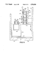
- FIG. 7 is a vertical side-section view of the mechanism of FIG. 6 showing the tube in a tilted position as a part is fed to the work station.
- FIG. 8 is a vertical side-section of the mechanism of FIG. 6 after feeding an individual part to the work station.
- FIG. 9 is a vertical end-section view of a portion of the device of the invention illustrating the storage of full tubes of parts to replace an empty tube.
- FIG. 10 is a vertical end-section view of the mechanism of FIG. 9 illustrating a new tube full of parts being moved into an unloading position.
- FIG. 11 is a fragmentary top view of the mechanism used to move the support member into position to receive a full tube of parts from a tube storage area.
- FIG. 12 is a fragmentary top view of the mechanism of FIG. 11 with the support member moved into a position to receive a full tube of parts from the full tube storage area.
- the part feeder of the invention is generally illustrated at 2, comprising a case 10 in which is mounted a base 20.
- a support member 30 Slideably mounted on base 20 is a support member 30 to which is pivotally affixed at 44 a tiltable arm 40 having mounted thereto an adjustable extension portion 40a which telescopes into arm 40 to adjust the effective length of arm 40.
- an air cylinder 90 Mounted to the end of extension portion 40a is an air cylinder 90 with a piston rod 86 which urges a tube engaging member into engagement with the end of a tube 50 containing parts to be fed to a work station 70 on the opposite end of the arm 40.
- arm 40 is also provided with other appendages, as will be described below, to support and position tube 50 containing a number of of parts 60.
- Parts 60 may comprise any type of part such as electronic parts which will be inserted by a robot arm into a printed circuit board.
- parts 60 will be illustrated herein as integrated circuit packages or "chips" of the dual-in-line rectangular package (DIP) type having two parallel spaced apart rows of pins depending perpendicular from opposite long edges of the bottom of the rectangular part.
- DIP dual-in-line rectangular package
- the invention may be used in connection with the dispensing of any kind of part which may be slideably received in a storage tube which will permit the part to slide in the tube while maintaining a particular orientation with respect to the tube.
- Tube 50 as shown in cross-section in FIG. 3, comprises a cross-sectional shape which corresponds to the particular shape of the part.
- tube 50 is provided with depending portions 52 to accommodate the pins 61 (see FIG. 4) of part 60 with a raised center section 54 between depending portions 52 to support the underside of rectangular part 60.
- Depending portions 52 and raised section 54 of tube 50 form an internal track in tube 50 on which each of the parts 60 may slide to facilitate removal of the parts from tube 50.
- both the width and height of tube 50 to approximately the width and height of part 60 coupled with the provision of an internal track beneath the part on which the part may slide
- a series of parts may be stacked end to end in the tube and removed one by one by sliding them out one end of tube 50.
- Examples of alternate cross-sectional shapes of tube 50, designated as 50', 50", and 50'", are shown together with tube 50 in FIG. 3A.
- a work station 70 which, in accordance with the invention, will receive a single part from tube 50.
- the particular shape of the work station will depend upon the shape and type of part to be dispensed from tube 50.
- Work station 70 is therefore designed as an independent member which can be interchangably mounted on the end of arm 40.
- each work station 70 will be different, depending upon the shape and type of part and the particular need for orientation or clamping of the part to enable proper interface with robotic grippers or end effectors to properly engage the part.
- each work station 70 will be provided with a sensor means to sense the presence or absence of a part in the work station indicative of tube 50 being empty or jammed.
- a sensor is shown in FIG. 2 comprising a photoelectric cell 34 and a light source 36.
- Work station 70 of the illustrated embodiment designed for the dispensing of DIP-type integrated circuit chips as best seen in FIGS. 2 and 4, comprises an upright part receiving member or receiver 72, which, in the illustrated embodiment, is anvil shaped having pointed or cammed sides 74 facing tube 50.
- the height and width of part receiving member 72 is approximately that of support surface 54 whereby part receiving member 72 may act as an extension of the aforementioned internal track in tube 50 so that a part 60 may smoothly slide from the adjacent end of tube 50 onto part receiving member 72 as will be described below.
- Cammed sides 74 provide lateral alignment for part 60 by contacting depending pins 61 on part 60 as it slides from tube 50 onto part receiving member 72. It will be noted again that while the shape of part receiving member will change with different parts, it should be in conformity with the shape of the track or part support portion 54 of tube 50 to facilitate smooth movement of a part from tube 50 onto part receiving member 72.
- Work station 70 may further comprise an end stop 76 to prevent part 60 from sliding off the end of part receiving member 72 and side stops 78 which are positioned parallel to part receiving member 72 but sufficiently far apart to not interfere with the exit of part 60 from tube 50 onto part receiving member 72.
- Side stops 78 in the illustrated embodiment, provide a stop for the end of tube 50 to laterally locate tube 50 along the length of arm 40 with respect to part receiving member 72.
- Tube 50 is urged against an appropriate stop in station 70, e.g., notch 71, by a fluid power means 90 such as an air cylinder which is mounted on tilting arm extension 40a.
- a fluid power means 90 such as an air cylinder which is mounted on tilting arm extension 40a.
- fluid power means 90 When fluid power means 90 is actuated in a forward direction toward tube 50, a piston rod 86, operationally attached to fluid power means 90, forces a wedge shaped member 80 attached to the end thereof into the end of tube 50 and urges tube against work station 70 into an appropriate receiving means in work station 70 such as notch 71 shown in FIGS. 5A-5D.
- Wedged shape member 80 which is removably attached to the end of piston rod 86, is dimensioned to generally conform to the dimensions of the particular parts tube to slightly flex the sidewalls of the tube as it penetrates the end thereof since tube 50 generally will be constructed from a flexible plastic material. This removably secures tube 50 to wedge 80 thereby permitting withdrawal of tube 50 from work station 70 when the supply of parts 60 therein is exhausted as will be described below.
- fluid power means 90 may be actuated in the opposite direction to withdraw member 80 and tube 50 thereon from work station 70 to permit removal of empty tube 50 and replacement with a full tube.
- the length of arm 40 may be adjusted to accommodate a number of different lengths of tube 50 by extending telescoping extension arm 40a therein which carries fluid power means 90, rod 86 and wedge member 80 thereon.
- a different wedge member 80 will be attached to the end of rod 86 to provide proper engagement with the new tube 50.
- support member 30 is shown in FIG. 5A in its parts dispensing position with fluid power means 90 urging rod 86 and wedge 80 thereon against and into the end of tube 50 to maintain the opposite end of tube 50 in and against work station 70.
- a stripper arm 88 mounted to extension arm 40a is located slightly behind tube 50, but close enough to engage the end of tube 50 when the tube is withdrawn from station 70 by the action of fluid power means 90 and rod 86 and wedge 80 attached thereto.
- Tube stack 100 Adjacent to support member 30 in case 10 is a stack 100 of tubes full of parts to replace the empty tube 50E when all parts have been dispensed.
- Tube stack 100 is vertically positioned between fixed stack wall 102 and adjustable stack wall 104 which may be moved or interchanged with a thinner or thicker wall to accommodate different dimensions of tubes.
- a spring steel wiper or spring 106 attached to wall 102 depends downwardly a sufficient distance (as also seen in FIGS. 9 and 10) to assist in directing a new tube into engagement with station 70 as will be described, as well as assisting in the removal or ejection of the empty parts tube.
- tube 50E has been withdrawn from station 70 by action of fluid power means 90 to retract rod 86 and wedge 80 thereon.
- the frictional engagement of wedge member 80 against the inner surfaces of the flexible sidewall of tube 50E causes tube 50E to retract with wedge 80 and rod 86 until the end edge of tube 50E is contacted by stripper 88 which forces tube 50E off wedge 80.
- the entire support member After withdrawal of empty tube 50E from station 70, the entire support member is moved to a position under the stack 100 of full tubes as shown in FIG. 5C. As support member 30 moves laterally, the empty tube, if still resting on arm 40, will come in contact with spring 106, as best seen in FIGS. 9 and 10 as well as FIG. 5C, to sweep empty tube 50E off arm 40 and through an appropriate opening 22 in base 20 of the apparatus.
- first fluid power means 90 urges rod 86 and wedge 80 into contact with the new full tube 50 pushing it forward into notch 71 in work station 70 with the guiding assistance of the cammed edge 66 on guide 62 and spring 106 to insure alignment between work station 70 and the internal track within tube 50.
- support member 30 is ready to be moved back to the dispensing position.
- arm 40 is pivoted upwardly, as shown in FIG. 7, to permit the first part 60 in tube 50 to slide onto part receiving member 72 in work station 70 where it engages end stop 76.
- Arm 40 is tilted or pivoted upwardly by second fluid power means 94 which is mounted on support member 30.
- Fluid power means or second means 94 are connected by piston rod 96 to an extension 42 which downwardly depends from arm 40.
- arm 40 pivots upward around pivot point 44. This permits a part 60 adjacent the end of tube 50 to slide out of tube 50 onto part receiving member 72 in work station 70.
- Subsequent actuation of cylinder 94 to extend rod 96 returns arm 40 to the horizontal position, as shown in FIG. 8, leaving part 60 on part receiving member 72 for subsequent removal, e.g., robotic removal, before the next part 60 is loaded onto part receiving member 72 in work station 70 by again tilting arm 40.
- arm 40 is returned to its horizontal position, as shown in FIG. 8, prior to removal of part 60 from part receiving member 72. Furthermore, by properly regulating the fluid supplied to fluid power means 94 and/or the pressure of the fluid via a pressure regulator, arm 40 may be caused to fall just sharply enough to provide a slight bounce which will have the effect of slightly separating the parts 60 remaining in tube 50 as well as providing a slight space between the part 60 on part receiving member 72 and the last part 60 in tube 50. Subsequent removal of part 60 from part receiving member 72 will then have no effect on other parts in tube 50. Control over the angle to which arm 40 is raised, as well as both the speed of ascent and descent of arm 40 may be controlled through control of fluid power means 94.
- empty tube 50 must be removed and replaced with a full tube 50a as previously discussed with respect to the top views of the feeding apparatus shown in FIGS. 5A-5D. This is accomplished, as shown in FIGS. 9-12, by moving support member 30 sideways under a vertical tube stack 100, comprising vertical walls 102 and 104, filled with full tubes 50a and supported by fingers 110 which extend under the bottom-most full tube 50a toward arm 40.
- Vertical tube stack 100 is capable of holding a number of full tubes and is accessible from either the side or the rear of the apparatus, i.e., the opposite end from work station 70 thus permitting restocking without interfering with the unloading of individual parts from the tube in position on arm 40.
- a tube sensor 136 may be located on stack wall 104 comprising a source of light and a light sensing means designed to detect reflected light from the side of a full tube.
- a black or non-reflective spot 138 placed on opposite stack wall 102 adsorbs the light and the non-reflectance indicates the absence of tubes in the stack to alert the operator to replenish the supply.
- fingers 110 slide into grooves 46 in arm 40 as shown in FIGS. 6-8 and 10. Fingers 110 are positioned slightly below the top surface of arm 40 so that when arm 40 is positioned beneath tube stack 100, the weight of the bottom tube will be on arm 40, not fingers 110. This assists in retaining the full tube 50a on arm 40 as arm 40 and support member 30 move back to the normal unloading position.
- fluid power means 90 are actuated, as previously described, to withdraw rod 86 and wedge member 80 with the aid of stripper 88 from tube 50 to release empty tube 50. This permits empty tube 50 to fall away, or be pushed aside by spring 106 as support member 30 and arm 40 move under tube stack 100. Cylinder 90 is then actuated in the opposite direction to urge member 80 against new tube 50a pushing it against and into engagement with work station 70.
- the entire design of the apparatus reflect the ability to locate a number of these devices side by side with the width of the device generally comprising the width of arm 40 and its support member 30 plus the additional width of tube stack 100, e.g., about 3 inches or so.
- the design provides for the ejectment of empty tube 50 through the bottom of the device rather than the side since a side exit would interfere with the placement of adjoining devices.
- FIGS. 11 and 12 sideways movement of support member 30 and tilting arm 40 thereon is controlled by an fluid power means 114 which is mounted to base 20 and connected to arm 118 and strip 112 via piston rod 116.
- fluid power means 114 and rod 116 are in an extended position, as shown in FIG. 11, support member 30 and tilting arm 40 are in their normal part unloading position.
- air cylinder 114 is actuated to withdraw rod 116 as shown in FIG. 12. This, in turn, also moves arm member 118 and strip 112 in the same direction, i.e., toward the right in FIG. 12, causing arms 126 to move on their pivot points 128 and 130 to move support member 30 normal to the movement of strip 112.
- Direction of movement of support member 30 perpendicular to the movement of strip 112 is, in turn, controlled by depending fingers or pins 120a and 120b which extend downward from support member 30 to ride in respective guide tracks 122a and 122b.
- air cylinder 90 is actuated to move member 80 back from engagement with tube 50, thus releasing tension on tube 50.
- Air cylinder 114 is then actuated to move support member 30 and arm 40 sideways under magazine 100 to obtain a new full tube 50a.
- fluid power means 90 is again actuated to urge wedge member 80 against and into the end of the new full tube 50a and to urge the opposite end of tube 50a into engagement with work station 70.
- air cylinder 114 While maintaining this tension on new tube 50a, air cylinder 114 is actuated in its opposite position to return support member 30 and arm 40, with new full tube 50a thereon, back to the normal unloading position where each part 60 can then be individually unloaded from tube 50a onto part receiving member 72 in work station 70 by the periodic tilting of arm 40 as previously described.
- the entire mechanism is controlled by the operation of three fluid power means, both to load the full tubes onto arm 40 and to individually unload the parts 60 from tube 50 onto part receiving member 72 for subsequent manual or robotic engagement to be inserted into a socket or for whatever other purpose it is desired to individually unload the parts from tube 50.
- Control of the three fluid power means may, in turn, be manual as, for example, by the manual actuation of fluid power means 94 each time a part is visually seen to be removed from part receiving member 72 to replace it with the next part in tube 50 by tilting of arm 40 or the control may be automatic, using a programmable control center such as, for example, the SMC Cylinder Controller ECC50, commercially available from the SMC Company.
- a programmable control center such as, for example, the SMC Cylinder Controller ECC50, commercially available from the SMC Company.
- the cycle time for unloading of each part may be programmed into the device to control the actuation cycle of air cylinder 96; to control the actuation of cylinder 90; and the number of parts in each tube; and to control the actuation of cylinder 114 to replace the empty tube with a new one.
- the invention provides a novel part feeder wherein a tube holding a number of parts such as, for example, integrated circuit chip packages is normally maintained in a horizontal position and intermittently tilted sufficiently to permit exit by gravity of one part from the tube to a work station followed by return of the tube to the horizontal position.
- a tube holding a number of parts such as, for example, integrated circuit chip packages
- the invention provides for means for storing of a vertical stack of additional full tubes which is independently accessible for restocking without interfering with tilting of the tube being unloaded. After emptying of the tube being unloaded, the invention provides for the disposal of the empty tube and replacement with a full tube from the tube stack.
Abstract
Description
Claims (15)
Priority Applications (1)
| Application Number | Priority Date | Filing Date | Title |
|---|---|---|---|
| US06/917,046 US4761106A (en) | 1986-10-09 | 1986-10-09 | Part feeder |
Applications Claiming Priority (1)
| Application Number | Priority Date | Filing Date | Title |
|---|---|---|---|
| US06/917,046 US4761106A (en) | 1986-10-09 | 1986-10-09 | Part feeder |
Publications (1)
| Publication Number | Publication Date |
|---|---|
| US4761106A true US4761106A (en) | 1988-08-02 |
Family
ID=25438268
Family Applications (1)
| Application Number | Title | Priority Date | Filing Date |
|---|---|---|---|
| US06/917,046 Expired - Fee Related US4761106A (en) | 1986-10-09 | 1986-10-09 | Part feeder |
Country Status (1)
| Country | Link |
|---|---|
| US (1) | US4761106A (en) |
Cited By (16)
| Publication number | Priority date | Publication date | Assignee | Title |
|---|---|---|---|---|
| US4950120A (en) * | 1989-02-27 | 1990-08-21 | Burndy Corporation | Apparatus and method for feeding card edge connectors and connector magazines |
| US4952109A (en) * | 1988-02-19 | 1990-08-28 | Excellon Automation | Modular feeding tray for vibrating conveyors |
| US5073078A (en) * | 1989-05-04 | 1991-12-17 | Vincenzo Merlo | Automatic intelligent magazine for electronic components |
| US5116185A (en) * | 1990-05-01 | 1992-05-26 | Lsi Logic Corp. | Vibratory tube-to-tube transfer system |
| US5117963A (en) * | 1990-12-12 | 1992-06-02 | Micron Technology, Inc. | System for automated handling of symmetrical supply tubes |
| US5190431A (en) * | 1991-07-03 | 1993-03-02 | Sym-Tek Systems, Inc. | Separation and transfer apparatus |
| US5217120A (en) * | 1989-08-31 | 1993-06-08 | Goldstar Co., Ltd. | Apparatus for loading and unloading sleeves for integrated circuit ester |
| US5328317A (en) * | 1991-06-13 | 1994-07-12 | Tenryu Technics Co., Ltd. | Stick feeder |
| US5702224A (en) * | 1995-12-22 | 1997-12-30 | Hitachi Electronics Engineering Co., Ltd. | Gravitational IC package transfer mechanism |
| US5733093A (en) * | 1995-12-22 | 1998-03-31 | Robodyne Corporation | Stack tube feeder |
| US5755548A (en) * | 1996-12-27 | 1998-05-26 | Amistar Corporation | Belt drive tube feeder for a surface mount placement system |
| WO1998047341A1 (en) * | 1997-04-15 | 1998-10-22 | Corfin Inc. | Automatic input and output tube handlers for use with an electronic component processing machine |
| US6719518B2 (en) * | 2001-10-15 | 2004-04-13 | Anadigics, Inc. | Portable tube holder apparatus |
| EP1976366A1 (en) * | 2007-03-30 | 2008-10-01 | Mydata Automation AB | Device and apparatus at a component mounting machine |
| CN108382822A (en) * | 2017-02-03 | 2018-08-10 | 发那科株式会社 | Parts feeder and component delivery machine people with the parts feeder |
| CN113816118A (en) * | 2021-11-19 | 2021-12-21 | 四川明泰电子科技有限公司 | IC chip detects material loading frock |
Citations (10)
| Publication number | Priority date | Publication date | Assignee | Title |
|---|---|---|---|---|
| US4149311A (en) * | 1977-09-22 | 1979-04-17 | Banner/Technical Devices Inc. | Work station for facilitating component assembly |
| US4194865A (en) * | 1977-05-12 | 1980-03-25 | Dai-Ichi Seiko Co., Ltd. | Insert loading apparatus in transfer encapsulation |
| US4234418A (en) * | 1978-06-23 | 1980-11-18 | Contrel Corporation | Dip-handling apparatus |
| JPS59172326A (en) * | 1983-03-22 | 1984-09-29 | Trio Kenwood Corp | Element feeder |
| JPS60197518A (en) * | 1984-03-15 | 1985-10-07 | Alps Electric Co Ltd | Parts feeder |
| US4575301A (en) * | 1982-10-22 | 1986-03-11 | Sasib S.P.A. | Automatic feeder device for cigarettes and similar rod-like articles |
| US4599026A (en) * | 1985-02-26 | 1986-07-08 | Amp Incorporated | Apparatus for providing a continuous supply of workpieces |
| US4618305A (en) * | 1983-11-23 | 1986-10-21 | Daymarc Corporation | Automatic feed apparatus and process for integrated circuits stored in tubes |
| US4629387A (en) * | 1984-05-18 | 1986-12-16 | Adcotech Corporation | DIP tube loading/unloading apparatus |
| US4647269A (en) * | 1985-07-01 | 1987-03-03 | Micro Component Technology, Inc. | Automatic integrated circuit transportation tube elevating and tilting device |
-
1986
- 1986-10-09 US US06/917,046 patent/US4761106A/en not_active Expired - Fee Related
Patent Citations (10)
| Publication number | Priority date | Publication date | Assignee | Title |
|---|---|---|---|---|
| US4194865A (en) * | 1977-05-12 | 1980-03-25 | Dai-Ichi Seiko Co., Ltd. | Insert loading apparatus in transfer encapsulation |
| US4149311A (en) * | 1977-09-22 | 1979-04-17 | Banner/Technical Devices Inc. | Work station for facilitating component assembly |
| US4234418A (en) * | 1978-06-23 | 1980-11-18 | Contrel Corporation | Dip-handling apparatus |
| US4575301A (en) * | 1982-10-22 | 1986-03-11 | Sasib S.P.A. | Automatic feeder device for cigarettes and similar rod-like articles |
| JPS59172326A (en) * | 1983-03-22 | 1984-09-29 | Trio Kenwood Corp | Element feeder |
| US4618305A (en) * | 1983-11-23 | 1986-10-21 | Daymarc Corporation | Automatic feed apparatus and process for integrated circuits stored in tubes |
| JPS60197518A (en) * | 1984-03-15 | 1985-10-07 | Alps Electric Co Ltd | Parts feeder |
| US4629387A (en) * | 1984-05-18 | 1986-12-16 | Adcotech Corporation | DIP tube loading/unloading apparatus |
| US4599026A (en) * | 1985-02-26 | 1986-07-08 | Amp Incorporated | Apparatus for providing a continuous supply of workpieces |
| US4647269A (en) * | 1985-07-01 | 1987-03-03 | Micro Component Technology, Inc. | Automatic integrated circuit transportation tube elevating and tilting device |
Cited By (20)
| Publication number | Priority date | Publication date | Assignee | Title |
|---|---|---|---|---|
| US4952109A (en) * | 1988-02-19 | 1990-08-28 | Excellon Automation | Modular feeding tray for vibrating conveyors |
| US4950120A (en) * | 1989-02-27 | 1990-08-21 | Burndy Corporation | Apparatus and method for feeding card edge connectors and connector magazines |
| US5073078A (en) * | 1989-05-04 | 1991-12-17 | Vincenzo Merlo | Automatic intelligent magazine for electronic components |
| US5217120A (en) * | 1989-08-31 | 1993-06-08 | Goldstar Co., Ltd. | Apparatus for loading and unloading sleeves for integrated circuit ester |
| US5116185A (en) * | 1990-05-01 | 1992-05-26 | Lsi Logic Corp. | Vibratory tube-to-tube transfer system |
| US5117963A (en) * | 1990-12-12 | 1992-06-02 | Micron Technology, Inc. | System for automated handling of symmetrical supply tubes |
| US5328317A (en) * | 1991-06-13 | 1994-07-12 | Tenryu Technics Co., Ltd. | Stick feeder |
| US5190431A (en) * | 1991-07-03 | 1993-03-02 | Sym-Tek Systems, Inc. | Separation and transfer apparatus |
| US5702224A (en) * | 1995-12-22 | 1997-12-30 | Hitachi Electronics Engineering Co., Ltd. | Gravitational IC package transfer mechanism |
| US5733093A (en) * | 1995-12-22 | 1998-03-31 | Robodyne Corporation | Stack tube feeder |
| US5755548A (en) * | 1996-12-27 | 1998-05-26 | Amistar Corporation | Belt drive tube feeder for a surface mount placement system |
| WO1998047341A1 (en) * | 1997-04-15 | 1998-10-22 | Corfin Inc. | Automatic input and output tube handlers for use with an electronic component processing machine |
| US5931629A (en) * | 1997-04-15 | 1999-08-03 | Corfin Inc. | Automatic input and output tube handlers for use with an electronic component processing equipment |
| US6719518B2 (en) * | 2001-10-15 | 2004-04-13 | Anadigics, Inc. | Portable tube holder apparatus |
| EP1976366A1 (en) * | 2007-03-30 | 2008-10-01 | Mydata Automation AB | Device and apparatus at a component mounting machine |
| CN108382822A (en) * | 2017-02-03 | 2018-08-10 | 发那科株式会社 | Parts feeder and component delivery machine people with the parts feeder |
| CN108382822B (en) * | 2017-02-03 | 2019-08-30 | 发那科株式会社 | Parts feeder and component delivery machine people with the parts feeder |
| US10455749B2 (en) * | 2017-02-03 | 2019-10-22 | Fanuc Corporation | Parts supply device and parts supply robot having the same |
| CN113816118A (en) * | 2021-11-19 | 2021-12-21 | 四川明泰电子科技有限公司 | IC chip detects material loading frock |
| CN113816118B (en) * | 2021-11-19 | 2022-02-11 | 四川明泰电子科技有限公司 | IC chip detects material loading frock |
Similar Documents
| Publication | Publication Date | Title |
|---|---|---|
| US4761106A (en) | Part feeder | |
| US6971833B1 (en) | Order picking system | |
| NL1004095C1 (en) | Method and device for supplying and placing components. | |
| US5271710A (en) | Device for loading articles onto an unstacking magazine and a loading method using this device | |
| CN106269005B (en) | Device and method for operating a rack of disposable pipette tips in a laboratory automation system, and laboratory automation system | |
| JPH04226243A (en) | Device to feed reel of tape material to packaging machine | |
| US5796616A (en) | Apparatus for automatically replenishing chips | |
| US4763811A (en) | Parts feeder | |
| JP2507265B2 (en) | Method and device for transferring articles to container | |
| JPS628370B2 (en) | ||
| US5190431A (en) | Separation and transfer apparatus | |
| US5547336A (en) | Magazine release assembly | |
| NL195037C (en) | Device for loading and unloading tubes for a test device for semiconductor circuits. | |
| CA1331028C (en) | Automatic supply and loading device for sheet items | |
| US5024348A (en) | Magazine assembly for labels or the like in a labeling machine | |
| US6192658B1 (en) | Method and apparatus for fitting a sheet-like article | |
| JP2023014589A (en) | Test tube array apparatus | |
| JP2006240718A (en) | Feeder of packaging materials for packing agricultural product in box, and device for packing agricultural product in box | |
| US5785489A (en) | Case-feeding unit in an automatic apparatus for packaging manufactured articles into cases and automatic case-feeding method relating to same | |
| JPH02189000A (en) | Method and apparatus for supply of electronic component | |
| JPS60153306A (en) | Device for supplying and discharging print circuit board | |
| US5217120A (en) | Apparatus for loading and unloading sleeves for integrated circuit ester | |
| JP7288406B2 (en) | Goods transfer device and picking system | |
| US5120191A (en) | Stack unloader for molded carrier ring components | |
| JPH07202482A (en) | Stopper insertion device into magazine |
Legal Events
| Date | Code | Title | Description |
|---|---|---|---|
| AS | Assignment |
Owner name: SEQUOIA AUTOMATION SYSTEMS, INC., SANTA CLARA, CA Free format text: ASSIGNMENT OF ASSIGNORS INTEREST.;ASSIGNORS:BROWN, ROBERT N.;FARQUHAR, JAMES J.;REEL/FRAME:004642/0482 Effective date: 19861205 Owner name: SEQUOIA AUTOMATION SYSTEMS, INC., A CORP OF CA, CA Free format text: ASSIGNMENT OF ASSIGNORS INTEREST;ASSIGNORS:BROWN, ROBERT N.;FARQUHAR, JAMES J.;REEL/FRAME:004642/0482 Effective date: 19861205 |
|
| AS | Assignment |
Owner name: ALLIANCE AUTOMATION SYSTEMS, INC., 400 TRABOLD ROA Free format text: ASSIGNMENT OF ASSIGNORS INTEREST.;ASSIGNOR:SEQUOIA AUTOMATION SYSTEMS, INC.,;REEL/FRAME:004837/0490 Effective date: 19880310 Owner name: ALLIANCE AUTOMATION SYSTEMS, INC., A MICHIGAN CORP Free format text: ASSIGNMENT OF ASSIGNORS INTEREST;ASSIGNOR:SEQUOIA AUTOMATION SYSTEMS, INC.,;REEL/FRAME:004837/0490 Effective date: 19880310 |
|
| AS | Assignment |
Owner name: AMBAC AUTOMATION CORP., 1418 UPFIELD DRIVE, CARROL Free format text: ASSIGNMENT OF ASSIGNORS INTEREST.;ASSIGNOR:ALLIANCE AUTOMATION SYSTEMS, INC.;REEL/FRAME:005535/0087 Effective date: 19900618 |
|
| REMI | Maintenance fee reminder mailed | ||
| FPAY | Fee payment |
Year of fee payment: 4 |
|
| SULP | Surcharge for late payment | ||
| REMI | Maintenance fee reminder mailed | ||
| LAPS | Lapse for failure to pay maintenance fees | ||
| FP | Expired due to failure to pay maintenance fee |
Effective date: 19960807 |
|
| STCH | Information on status: patent discontinuation |
Free format text: PATENT EXPIRED DUE TO NONPAYMENT OF MAINTENANCE FEES UNDER 37 CFR 1.362 |