US4762053A - Replacement filtered soffit ventilator - Google Patents
Replacement filtered soffit ventilator Download PDFInfo
- Publication number
- US4762053A US4762053A US07/056,768 US5676887A US4762053A US 4762053 A US4762053 A US 4762053A US 5676887 A US5676887 A US 5676887A US 4762053 A US4762053 A US 4762053A
- Authority
- US
- United States
- Prior art keywords
- frame
- loop
- soffit
- bracket
- opening
- Prior art date
- Legal status (The legal status is an assumption and is not a legal conclusion. Google has not performed a legal analysis and makes no representation as to the accuracy of the status listed.)
- Expired - Fee Related
Links
Images
Classifications
-
- F—MECHANICAL ENGINEERING; LIGHTING; HEATING; WEAPONS; BLASTING
- F24—HEATING; RANGES; VENTILATING
- F24F—AIR-CONDITIONING; AIR-HUMIDIFICATION; VENTILATION; USE OF AIR CURRENTS FOR SCREENING
- F24F13/00—Details common to, or for air-conditioning, air-humidification, ventilation or use of air currents for screening
- F24F13/28—Arrangement or mounting of filters
-
- E—FIXED CONSTRUCTIONS
- E04—BUILDING
- E04D—ROOF COVERINGS; SKY-LIGHTS; GUTTERS; ROOF-WORKING TOOLS
- E04D13/00—Special arrangements or devices in connection with roof coverings; Protection against birds; Roof drainage; Sky-lights
- E04D13/15—Trimming strips; Edge strips; Fascias; Expansion joints for roofs
- E04D13/152—Trimming strips; Edge strips; Fascias; Expansion joints for roofs with ventilating means in soffits or fascias
Definitions
- the invention relates to roof soffit ventilators, and more specifically, relates to an improved soffit ventilator with a replaceable filter element.
- Proper and effective attic ventilation of a residential building is necessary in order to prevent accumulation of water vapor in the attic or vacant space below the roof of a building.
- Such water vapor will condense in a cold attic or crawl space above the living quarters sufficiently to reduce the rating of insulation installed in the attic and can have deleterious effects on the structure of the roof.
- An important adjunct of such an attic ventilation system is the soffit ventilator, which cooperates with a roof ridge ventilator or other roof ventilators so that such water vapor accumulation in the attic can be avoided.
- a roof ridge ventilator is disclosed in my U.S. Pat. No. 4,325,290.
- Conventional attic ventilation systems employ a fixed soffit ventilator which includes an opening in the soffit over which a louvered metal plate is secured.
- the metal plate may be provided with a metal screen designed to prevent the intrusion of insects and other pests.
- a major disadvantage of conventional soffit ventilators is that over extended periods of use, the ventilator openings become clogged with dirt, trapped insect remains and/or other organic material, thereby severely restricting and ultimately preventing vital air circulation capability.
- conventional soffit ventilators are fixed to the soffit and often are sealed thereto by repeated painting, it is quite difficult, if not impossible, to remove them for cleaning, without damaging the ventilators so that they must be replaced.
- a soffit ventilator which is accessible for cleaning without dismantling from the soffit and which has a filter element which is both replaceable and capable of preventing incursion of substantially all insects or other pests into the attic through the soffit ventilator without restricting air flow.
- the invention provides a filtered soffit ventilator having a replaceable filter and which permits the free flow of air through the ventilator while restricting the access of insects to the interior of the roof.
- a bracket is fixed within a ventilation opening in the soffit and is dimensioned to line that opening.
- a filter frame is provided which is replaceably secured within the bracket, either by fasteners such as wing nuts or a combination of wing nuts and a hinge.
- the filter frame is constructed to retain a replaceable filter media therein between a mesh cloth on the exterior side of the frame, and a specially designed compressible loop on the inside of the frame.
- the filter frame and enclosed filter media are dimensioned to cover the opening in the soffit so that air must pass through the filter.
- the frame In operation, when the filter becomes clogged, the frame is detached from the bracket by twisting the wing nuts, and the filter media is replaced by unfastening the compressible loop. In cases where the frame is hinged in the bracket, the frame can be pivoted downwardly for easy access to the filter media. Efficient below-the-roof ventilation of a building is thus maintained without dismantling or damaging the ventilator structure.
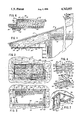
- FIG. 1 depicts a fragmentary side elevational view of a conventional residential building roof partially in section to show installation of the filtered soffit ventilator embodying the invention
- FIG. 2 is a top plan view of said ventilator shown installed in FIG. 1;
- FIG. 3 is a bottom plan view of said ventilator viewed from below the soffit installation of FIG. 1;
- FIG. 4 is a plan view of the ventilator shown in FIG. 2 with the compressible loop compressed for replacement of the filter element;
- FIG. 5 is a perspective view of the ventilator of the invention showing the hinging action of the compressible loop
- FIG. 6 is an enlarged partial sectional view taken along line 6--6 of FIG. 3 and in the direction indicated generally;
- FIG. 7 is a perspective view of an alternate embodiment of the ventilator embodying the invention shown installed in a soffit.
- a conventional roof 10 and attic or roof crawl space 12 of a residential building 13 is depicted in section, with the air flow pattern therethrough indicated by arrows designated 14.
- the roof 10 is shown having a roof ridge ventilator 16 installed over the ridge opening 17 in a conventional manner.
- the attic or space 12 is bounded at its upper margin by the roof 10, and at its lower margin by the ceiling 18, which in the present embodiment is shown with an overlying layer of insulation 20.
- the air flow 14 enters the attic 12 through opening 22 in the soffit 24.
- Multiple soffit openings 22 preferably are provided in a typical roof 10.
- Soffit ventilators are normally located in the openings 22 to restrict the entrance of insects, other pests and debris into the attic 12.
- the ventilator of the invention is designated generally by the reference character 32 and is shown positioned within the opening 22.
- Conventional ventilators are generally flat plates of sheet metal or other rigid material into which a plurality of louvers or air slots are provided by stamping or other fabrication techniques.
- Conventional ventilators of this type may be provided with a sheet of screen mesh behind the louvers to act as a filter.
- conventional ventilators are only marginally effective in restricting smaller insects from entering the attic 12 through the soffit openings 22.
- conventional ventilators are subject to clogging of the slots by dirt, insect debris and other organic matter or by repeated painting. This clogging restricts air flow through the soffit openings 22, and is detrimental to roof longevity.
- the filtered soffit ventilator 32 of the invention is illustrated in greater detail in FIGS. 2, 3 and 6.
- the ventilator 32 is shown mounted in the opening 22 of the soffit 24.
- the opening 22 is lined by a bracket 34, which in the present embodiment is rectangular and has an exterior facial flange 36, a central wall 38 and an interior lip 40 projecting toward the center of the opening 22. Both the facial flange 36 and the interior lip 40 extend around the entire periphery of the opening 22.
- the flange 36 is also provided with a pair of sides 42, 44, an upper portion 46 and a lower portion 48 (shown best in FIG. 3), each of which is provided with at least one mounting aperture 50 for a threaded fastener 52 to secure the bracket 34 to the soffit 24.
- the sides 42, 44, and the upper and lower portions 46 and 48 are also each provided with an aperture 54 through which a long-armed wing nut or similar fastener 56 is threaded for axial rotation thereabout.
- a frame 58 is shown having an exterior face 60 and an interior face 62 and is mounted within the bracket 34 so that the interior face 62 engages the interior lip 40, and the exterior face 60 is within reach of the wing nuts 56.
- the frame 58 is thus retained within the bracket 34.
- Both the exterior and interior faces 60 and 62 may be said to form inwardly projecting peripheral lips.
- a rigid sheet of mesh or screen cloth forms a grill or filter retainer 64, which is fastened to the exterior face 60 of the frame 58, and for aesthetics, may be placed directly underneath the face 60.
- a sheet of porous filter media 66 is replaceably located within the frame 58.
- the media 66 is fabricated of synthetic fibrous material such as fiberglass and is provided in a sheet which fills the interior of the frame 58.
- the media 66 has a fine mesh which prevents penetration by the smallest insect pests, yet allows the free flow of air therethrough and facilitates the air flow 14.
- the media 66 is retained within the frame 58 and against the grill 64 by a compressible retaining loop 68.
- the loop 68 is a single strand of flexibly rigid metal wire having two ends 70 and 72.
- the loop 68 is configured by bending or other methods into the generally rectangular shape shown best in FIG. 2, so that the ends 70, 72 are both located on one of the two sides 74 or 76 of the frame 58 and are mounted to a hinge 78 attached, in the preferred embodiment, to the side 76 of the frame 58.
- the loop 68 is configured to have a generally truncated end 80 designed to be inserted underneath the side 74 opposite the hinge 78.
- the loop is also provided with upper and lower truncated extensions 82 and 84, each of which can be inserted underneath the respective upper and lower sides 86, 88 of the interior side 62.
- the loop 68 is also provided with upper and lower gripping portions 90 and 92, the use of which will be described presently.
- the loop 68 is swung on hinge 78 so that the end 80 is adjacent to the side 74 of the frame interior side 62.
- the loop 68 is then forced against its own biasing force underneath the side 74 of the interior side 62.
- the upper and lower gripping portions 90 and 92 then are grasped by the installer to squeeze those portions together, so that the upper and lower extensions 82, 84 may be inserted underneath the respective upper and lower sides 86, 88 of the frame 58.
- the installer then releases the gripping portions 90, 92 to allow the loop 68 to spring against the interior of the frame 58.
- the media 66 is thus releasably secured within the frame 58.
- FIG. 7 an alternate embodiment of the present soffit ventilator 33 is shown, wherein the frame 58 is secured within the bracket 34 by one-armed wing nuts 56 as shown previously on only three sides, and is provided with a hinge 94 on the fourth side which is also mounted to the bracket 34.
- the hinge 94 may be located on any one of the four sides 74, 76, 86, 88 of the frame exterior 60.
- the ventilator 33 depicted in FIG. 7 is otherwise identical to the ventilator depicted in FIGS. 1-6.
- the filtered soffit ventilator 32 of the invention is secured within the opening 22 of the soffit 24 by the bracket 34.
- the frame 58 in which the media 66 is retained between the grill 64 and the compressible loop 68, is releasably secured against the interior lip 40 of the bracket 34 by the one-armed wing nuts 56.
- the frame 58 is removed from the bracket 34, and the compressible loop 68 is released by squeezing together the gripping portions 90 and 92 to allow the replacement of the media 66.
- the frame 58 is hinged to the bracket 34 to conveniently drop down upon release of the wing nut 56, exposing the compressible loop 68 and filter media 66 for replacement.
- the filtered soffit ventilator of the invention provides a covering for a soffit opening which allows the free flow of air therethrough while restricting the penetration of insect pests, dirt and other unwanted material into the attic area.
- the filter media is easily accessible and may be replaced periodically to optimize air flow through the attic.
Abstract
Description
Claims (6)
Priority Applications (1)
| Application Number | Priority Date | Filing Date | Title |
|---|---|---|---|
| US07/056,768 US4762053A (en) | 1987-06-02 | 1987-06-02 | Replacement filtered soffit ventilator |
Applications Claiming Priority (1)
| Application Number | Priority Date | Filing Date | Title |
|---|---|---|---|
| US07/056,768 US4762053A (en) | 1987-06-02 | 1987-06-02 | Replacement filtered soffit ventilator |
Publications (1)
| Publication Number | Publication Date |
|---|---|
| US4762053A true US4762053A (en) | 1988-08-09 |
Family
ID=22006473
Family Applications (1)
| Application Number | Title | Priority Date | Filing Date |
|---|---|---|---|
| US07/056,768 Expired - Fee Related US4762053A (en) | 1987-06-02 | 1987-06-02 | Replacement filtered soffit ventilator |
Country Status (1)
| Country | Link |
|---|---|
| US (1) | US4762053A (en) |
Cited By (37)
| Publication number | Priority date | Publication date | Assignee | Title |
|---|---|---|---|---|
| FR2640030A1 (en) * | 1988-12-07 | 1990-06-08 | Branchu Yves | Filtering vent intended for construction parts or construction elements of buildings, premises or compartments, inhabited or non-inhabited |
| US4995308A (en) * | 1989-05-24 | 1991-02-26 | Alumax Inc. | Roof ventilating apparatus |
| US5022314A (en) * | 1989-05-24 | 1991-06-11 | Alumax Inc. | Roof ventilating apparatus |
| US5035172A (en) * | 1989-05-24 | 1991-07-30 | Alumax Inc. | Roof ventilating apparatus |
| US5075000A (en) * | 1990-05-22 | 1991-12-24 | Filtercorp, Inc. | Filter pad holder |
| US5133789A (en) * | 1991-11-13 | 1992-07-28 | Smith Mark G | Expandable filter assembly |
| US5143604A (en) * | 1990-05-22 | 1992-09-01 | Filtercorp, Inc. | One-way guided filter pad assembly |
| US5183488A (en) * | 1992-04-30 | 1993-02-02 | Research Products Corporation | Multi-stage filter frame assembly |
| WO1993010405A1 (en) * | 1991-11-15 | 1993-05-27 | Rotter Martin J | Air-permeable barrier for soffit vent |
| US5601715A (en) * | 1995-09-08 | 1997-02-11 | New Pig Corporation | Mutli-stage grease trap filter and skimmer |
| US5690719A (en) * | 1995-10-19 | 1997-11-25 | Hodge; Joseph | Removable filter for a forced air duct grill |
| EP0769664A3 (en) * | 1995-10-17 | 1998-01-21 | Matsushita Electric Industrial Co., Ltd. | Filter casing |
| EP1043052A1 (en) * | 1999-04-09 | 2000-10-11 | Alain Cocault | Housing for receiving a funtional part and assembly of such housings |
| US6145255A (en) * | 1998-04-23 | 2000-11-14 | Building Materials Corporation Of America | Soffit vent |
| AU726665B2 (en) * | 1997-03-06 | 2000-11-16 | Robert Charles Allen | Gable end roof ventilator |
| US6220956B1 (en) | 2000-02-14 | 2001-04-24 | Jay T. Kilian | Soffit fan |
| US6267668B1 (en) | 1998-12-17 | 2001-07-31 | Diversi-Plast Products, Inc. | Ridge cap vent |
| US6450882B1 (en) | 2000-08-30 | 2002-09-17 | Liberty Diversified Industries, Inc. | Precipitation resistant ridge vent |
| US6463708B1 (en) | 1999-11-15 | 2002-10-15 | Victor W. Anderson | Roof shingle and system |
| US20030230062A1 (en) * | 2002-06-14 | 2003-12-18 | 3M Innovative Properties Company | Filter assembly |
| US20030230063A1 (en) * | 2002-06-14 | 2003-12-18 | 3M Innovative Properties Company | Filter frame |
| US20030230061A1 (en) * | 2002-06-14 | 2003-12-18 | 3M Innovative Properties Company | Collapsible pleated filter element |
| US6835128B1 (en) * | 2000-12-15 | 2004-12-28 | Mark B. Olson | Ceiling mounted air filtering and distribution apparatus operated independently of any HVAC system |
| US20050138905A1 (en) * | 2003-12-24 | 2005-06-30 | Kubokawa James O. | Filter assembly |
| US20060116069A1 (en) * | 2004-11-30 | 2006-06-01 | Gary Urbanski | Baffle-vent for S-tile ridge |
| US20070094953A1 (en) * | 2005-09-30 | 2007-05-03 | Galeazzo John P | Roof vents |
| US20070117505A1 (en) * | 2005-11-23 | 2007-05-24 | Wey Scott V | Sealable ridge vent for tile roof |
| US20100263301A1 (en) * | 2006-09-11 | 2010-10-21 | Mr. Ronald E. Prass, JR. | Energy-saving baffle |
| US20130247480A1 (en) * | 2011-08-24 | 2013-09-26 | Michael Duane Ridgway | Serviceable soffit vent |
| US9695594B2 (en) | 2015-06-16 | 2017-07-04 | Liberty Diversified International, Inc. | Ridge vent |
| US20170307250A1 (en) * | 2015-01-13 | 2017-10-26 | Knauf Gips Kg | Air outlet for a ventilation device |
| US10151500B2 (en) | 2008-10-31 | 2018-12-11 | Owens Corning Intellectual Capital, Llc | Ridge vent |
| US10201773B2 (en) * | 2015-11-18 | 2019-02-12 | Robert C. Zurmuehlen | Filter retainer arrangement |
| US10280612B2 (en) * | 2016-12-26 | 2019-05-07 | Hauseco Co., Ltd. | Ventilation structure |
| US10370855B2 (en) | 2012-10-10 | 2019-08-06 | Owens Corning Intellectual Capital, Llc | Roof deck intake vent |
| JP2020146640A (en) * | 2019-03-14 | 2020-09-17 | 三機工業株式会社 | Air filter |
| US11434642B2 (en) | 2019-01-30 | 2022-09-06 | Liberty Plastics, Inc. | Adhesive assembled ridge vent |
Citations (6)
| Publication number | Priority date | Publication date | Assignee | Title |
|---|---|---|---|---|
| US1801949A (en) * | 1928-10-20 | 1931-04-21 | Miles E Heath | Register filter |
| US3154393A (en) * | 1958-04-18 | 1964-10-27 | Fiber Bond Corp | Gas filter |
| US3570220A (en) * | 1969-04-02 | 1971-03-16 | John V Felter | Combined access door and filter holder |
| US3774377A (en) * | 1972-04-21 | 1973-11-27 | American Air Filter Co | Filter assembly with replaceable filter element |
| US4325290A (en) * | 1980-10-06 | 1982-04-20 | Air Vent, Inc. | Filtered roof ridge ventilator |
| US4550648A (en) * | 1983-07-11 | 1985-11-05 | Eagle Jon R | Attic ventilation system |
-
1987
- 1987-06-02 US US07/056,768 patent/US4762053A/en not_active Expired - Fee Related
Patent Citations (6)
| Publication number | Priority date | Publication date | Assignee | Title |
|---|---|---|---|---|
| US1801949A (en) * | 1928-10-20 | 1931-04-21 | Miles E Heath | Register filter |
| US3154393A (en) * | 1958-04-18 | 1964-10-27 | Fiber Bond Corp | Gas filter |
| US3570220A (en) * | 1969-04-02 | 1971-03-16 | John V Felter | Combined access door and filter holder |
| US3774377A (en) * | 1972-04-21 | 1973-11-27 | American Air Filter Co | Filter assembly with replaceable filter element |
| US4325290A (en) * | 1980-10-06 | 1982-04-20 | Air Vent, Inc. | Filtered roof ridge ventilator |
| US4550648A (en) * | 1983-07-11 | 1985-11-05 | Eagle Jon R | Attic ventilation system |
Cited By (49)
| Publication number | Priority date | Publication date | Assignee | Title |
|---|---|---|---|---|
| FR2640030A1 (en) * | 1988-12-07 | 1990-06-08 | Branchu Yves | Filtering vent intended for construction parts or construction elements of buildings, premises or compartments, inhabited or non-inhabited |
| US4995308A (en) * | 1989-05-24 | 1991-02-26 | Alumax Inc. | Roof ventilating apparatus |
| US5022314A (en) * | 1989-05-24 | 1991-06-11 | Alumax Inc. | Roof ventilating apparatus |
| US5035172A (en) * | 1989-05-24 | 1991-07-30 | Alumax Inc. | Roof ventilating apparatus |
| US5075000A (en) * | 1990-05-22 | 1991-12-24 | Filtercorp, Inc. | Filter pad holder |
| US5143604A (en) * | 1990-05-22 | 1992-09-01 | Filtercorp, Inc. | One-way guided filter pad assembly |
| US5133789A (en) * | 1991-11-13 | 1992-07-28 | Smith Mark G | Expandable filter assembly |
| WO1993010405A1 (en) * | 1991-11-15 | 1993-05-27 | Rotter Martin J | Air-permeable barrier for soffit vent |
| US5238450A (en) * | 1991-11-15 | 1993-08-24 | Rotter Martin J | Air-permeable barrier for soffit vent |
| US5183488A (en) * | 1992-04-30 | 1993-02-02 | Research Products Corporation | Multi-stage filter frame assembly |
| US5601715A (en) * | 1995-09-08 | 1997-02-11 | New Pig Corporation | Mutli-stage grease trap filter and skimmer |
| EP0769664A3 (en) * | 1995-10-17 | 1998-01-21 | Matsushita Electric Industrial Co., Ltd. | Filter casing |
| US5690719A (en) * | 1995-10-19 | 1997-11-25 | Hodge; Joseph | Removable filter for a forced air duct grill |
| AU726665B2 (en) * | 1997-03-06 | 2000-11-16 | Robert Charles Allen | Gable end roof ventilator |
| US6145255A (en) * | 1998-04-23 | 2000-11-14 | Building Materials Corporation Of America | Soffit vent |
| US6267668B1 (en) | 1998-12-17 | 2001-07-31 | Diversi-Plast Products, Inc. | Ridge cap vent |
| US6599184B2 (en) | 1998-12-17 | 2003-07-29 | Diversi-Plast Products, Inc. | Ridge cap vent |
| US6458029B2 (en) | 1998-12-17 | 2002-10-01 | Diversi-Plast Products, Inc. | Ridge cap vent |
| EP1043052A1 (en) * | 1999-04-09 | 2000-10-11 | Alain Cocault | Housing for receiving a funtional part and assembly of such housings |
| FR2791903A1 (en) * | 1999-04-09 | 2000-10-13 | Alain Cocault | HOUSING RECEIVING A FUNCTIONAL ELEMENT AND BATTERY THEREOF |
| US6463708B1 (en) | 1999-11-15 | 2002-10-15 | Victor W. Anderson | Roof shingle and system |
| US6220956B1 (en) | 2000-02-14 | 2001-04-24 | Jay T. Kilian | Soffit fan |
| US20080125028A1 (en) * | 2000-08-30 | 2008-05-29 | Liberty Diversified Industries | Precipitation resistant ridge vent |
| US20080182507A1 (en) * | 2000-08-30 | 2008-07-31 | Liberty Diversified Industries | Precipitation resistant ridge vent |
| US6450882B1 (en) | 2000-08-30 | 2002-09-17 | Liberty Diversified Industries, Inc. | Precipitation resistant ridge vent |
| US6623354B2 (en) | 2000-08-30 | 2003-09-23 | Liberty Diversified Industries | Precipitation resistant ridge vent |
| US6835128B1 (en) * | 2000-12-15 | 2004-12-28 | Mark B. Olson | Ceiling mounted air filtering and distribution apparatus operated independently of any HVAC system |
| US6860916B2 (en) | 2002-06-14 | 2005-03-01 | 3M Innovative Properties Company | Filter assembly |
| US6740137B2 (en) | 2002-06-14 | 2004-05-25 | 3M Innovative Properties Company | Collapsible pleated filter element |
| US6955702B2 (en) | 2002-06-14 | 2005-10-18 | 3M Innovative Properties Company | Filter frame |
| US20030230061A1 (en) * | 2002-06-14 | 2003-12-18 | 3M Innovative Properties Company | Collapsible pleated filter element |
| US20030230063A1 (en) * | 2002-06-14 | 2003-12-18 | 3M Innovative Properties Company | Filter frame |
| US20030230062A1 (en) * | 2002-06-14 | 2003-12-18 | 3M Innovative Properties Company | Filter assembly |
| US20050138905A1 (en) * | 2003-12-24 | 2005-06-30 | Kubokawa James O. | Filter assembly |
| US7169202B2 (en) | 2003-12-24 | 2007-01-30 | 3M Innovative Properties Company | Filter assembly |
| US20060116069A1 (en) * | 2004-11-30 | 2006-06-01 | Gary Urbanski | Baffle-vent for S-tile ridge |
| US7562498B2 (en) * | 2005-09-30 | 2009-07-21 | Galeazzo John P | Roof vents |
| US20070094953A1 (en) * | 2005-09-30 | 2007-05-03 | Galeazzo John P | Roof vents |
| US20070117505A1 (en) * | 2005-11-23 | 2007-05-24 | Wey Scott V | Sealable ridge vent for tile roof |
| US20100263301A1 (en) * | 2006-09-11 | 2010-10-21 | Mr. Ronald E. Prass, JR. | Energy-saving baffle |
| US10151500B2 (en) | 2008-10-31 | 2018-12-11 | Owens Corning Intellectual Capital, Llc | Ridge vent |
| US20130247480A1 (en) * | 2011-08-24 | 2013-09-26 | Michael Duane Ridgway | Serviceable soffit vent |
| US10370855B2 (en) | 2012-10-10 | 2019-08-06 | Owens Corning Intellectual Capital, Llc | Roof deck intake vent |
| US20170307250A1 (en) * | 2015-01-13 | 2017-10-26 | Knauf Gips Kg | Air outlet for a ventilation device |
| US9695594B2 (en) | 2015-06-16 | 2017-07-04 | Liberty Diversified International, Inc. | Ridge vent |
| US10201773B2 (en) * | 2015-11-18 | 2019-02-12 | Robert C. Zurmuehlen | Filter retainer arrangement |
| US10280612B2 (en) * | 2016-12-26 | 2019-05-07 | Hauseco Co., Ltd. | Ventilation structure |
| US11434642B2 (en) | 2019-01-30 | 2022-09-06 | Liberty Plastics, Inc. | Adhesive assembled ridge vent |
| JP2020146640A (en) * | 2019-03-14 | 2020-09-17 | 三機工業株式会社 | Air filter |
Similar Documents
| Publication | Publication Date | Title |
|---|---|---|
| US4762053A (en) | Replacement filtered soffit ventilator | |
| US4776262A (en) | Filtered insulation baffle | |
| US4699045A (en) | Housing for foundation ventilator | |
| US4502368A (en) | Air vent cover | |
| US4325290A (en) | Filtered roof ridge ventilator | |
| US6264713B1 (en) | Media filter assembly having replaceable filter element | |
| US4550648A (en) | Attic ventilation system | |
| CA2289769C (en) | Improved roof closure vent system | |
| US4208010A (en) | Ventilator assembly | |
| US6138424A (en) | Vent apparatus for attachment to a building structure | |
| US5370722A (en) | Filtering assembly for air intake | |
| US5302283A (en) | Leaf guard and strainer assembly for a gutter downspout | |
| US6192640B1 (en) | Double divisible connector frame for mounting air grilles and louvers to heating and cooling duct outlets | |
| US6422935B1 (en) | Air vent covering assembly | |
| US2850269A (en) | Cooling pad hanger systems | |
| US2463723A (en) | Air filter | |
| US6973757B2 (en) | Drain system for screen enclosures | |
| US4920867A (en) | Chimney screen | |
| US4315455A (en) | Adjustable soffit vent | |
| GB2211287A (en) | Roof ventilator | |
| EP0753619B1 (en) | Device for passing a treating fluid through a textile material or the like | |
| WO1997034348A1 (en) | Cooler for fitting on a control box | |
| JPH112445A (en) | Ventilation system for indoor air | |
| KR200239300Y1 (en) | Marine louvers | |
| KR102551945B1 (en) | Ventilation and fine dust cut off selective dustproof screen |
Legal Events
| Date | Code | Title | Description |
|---|---|---|---|
| AS | Assignment |
Owner name: AIR VENT INC. 4801 N. PROSPECT ROAD, PEORIA HEIGHT Free format text: ASSIGNMENT OF ASSIGNORS INTEREST.;ASSIGNOR:WOLFERT, CLARKE K.;REEL/FRAME:004725/0531 Effective date: 19870526 |
|
| FEPP | Fee payment procedure |
Free format text: PAYOR NUMBER ASSIGNED (ORIGINAL EVENT CODE: ASPN); ENTITY STATUS OF PATENT OWNER: LARGE ENTITY |
|
| FPAY | Fee payment |
Year of fee payment: 4 |
|
| FEPP | Fee payment procedure |
Free format text: PAYOR NUMBER ASSIGNED (ORIGINAL EVENT CODE: ASPN); ENTITY STATUS OF PATENT OWNER: LARGE ENTITY Free format text: PAYER NUMBER DE-ASSIGNED (ORIGINAL EVENT CODE: RMPN); ENTITY STATUS OF PATENT OWNER: LARGE ENTITY |
|
| FPAY | Fee payment |
Year of fee payment: 8 |
|
| REMI | Maintenance fee reminder mailed | ||
| LAPS | Lapse for failure to pay maintenance fees | ||
| FP | Lapsed due to failure to pay maintenance fee |
Effective date: 20000809 |
|
| AS | Assignment |
Owner name: AIR VENT INC., TEXAS Free format text: ASSIGNMENT OF ASSIGNORS INTEREST;ASSIGNOR:WOLFERT, CLARKE K.;REEL/FRAME:016987/0339 Effective date: 19820526 |
|
| STCH | Information on status: patent discontinuation |
Free format text: PATENT EXPIRED DUE TO NONPAYMENT OF MAINTENANCE FEES UNDER 37 CFR 1.362 |