US4765734A - Digitally encoded alpha-numeric projector slide and systems for using the same - Google Patents
Digitally encoded alpha-numeric projector slide and systems for using the same Download PDFInfo
- Publication number
- US4765734A US4765734A US06/866,214 US86621486A US4765734A US 4765734 A US4765734 A US 4765734A US 86621486 A US86621486 A US 86621486A US 4765734 A US4765734 A US 4765734A
- Authority
- US
- United States
- Prior art keywords
- information
- image
- alphanumeric
- writing
- projector slide
- Prior art date
- Legal status (The legal status is an assumption and is not a legal conclusion. Google has not performed a legal analysis and makes no representation as to the accuracy of the status listed.)
- Expired - Lifetime
Links
Images


Classifications
-
- G—PHYSICS
- G03—PHOTOGRAPHY; CINEMATOGRAPHY; ANALOGOUS TECHNIQUES USING WAVES OTHER THAN OPTICAL WAVES; ELECTROGRAPHY; HOLOGRAPHY
- G03B—APPARATUS OR ARRANGEMENTS FOR TAKING PHOTOGRAPHS OR FOR PROJECTING OR VIEWING THEM; APPARATUS OR ARRANGEMENTS EMPLOYING ANALOGOUS TECHNIQUES USING WAVES OTHER THAN OPTICAL WAVES; ACCESSORIES THEREFOR
- G03B23/00—Devices for changing pictures in viewing apparatus or projectors
Definitions
- the present invention relates generally to a photographic projector slide, and is particularly concerned with a system for concurrently storing and retrieving information concerning images held in projector slides.
- a positive film image is developed and mounted in a projector slide frame.
- the projector slide frame is a flat, square member having a rectangular opening or window in its central portion.
- the frame is constructed from a rigid, economical material such as cardboard or plastic.
- a photographic film image is positioned in the window between the two panels in any desired manner.
- Devices are also made to type information directly on a slide frame border. Such devices are elaborate and have drawbacks which include limited storage capacity, difficulty of changing information and general lack of machine readability.
- a conventional digital bar code could also be utilized to identify images held in a projector slide. While a bar code is machine readable, it has a low data capacity storage and it is difficult to change or add information once a bar code is printed.
- Magnetic media for storing encoded information is well known.
- Conventional magnetic read and write heads are utilized for detecting and encoding desired information on a magnetic media. Information is easily encoded or changed.
- Common examples of the use of such magnetic media includes credit cards, band debit cards, tickets and security access cards.
- a slide comprises a frame having a window in which a transparency is mounted in a conventional manner.
- One side of the slide is extended to accommodate a magnetic layer.
- the sound slide includes an arcuate sound track, a spiral-shaped sound track and other sound track configurations.
- U.S. Pat. No. 4,014,604 issued to Schwartz in March of 1977, also discloses a sound slide. This sound slide is identical to that described above with reference to the U.S. Pat. No. 4,102,569 patent.
- the sound track portion is contiguous to the image bearing portion and has spiral, arcuate, parallel and sinuous track configurations.
- U.S. Pat. No. 3,883,2308 issued to Dimitracopoulos in May of 1975, discloses an audiovisual slide with an adjacent sound and information track.
- Each slide includes a slide mount and a sound or information track.
- the sound or information track is positioned on the projector slide in many different configurations.
- the sound or information track is parallel to an edge of the projector slide.
- U.S. Pat. No. 3,876,297 issued to Appeldorn et al. in April of 1977, discloses an apparatus for audio identification of a photographic transparency mounted in a slide frame.
- a projector is constructed for use with a slide frame clip having a base attached to a slide frame by an adhesive layer.
- the clip also includes a strip of magnetic tape which is affixed to a base. The magnetic tape is used for sound recording.
- a base includes a bottom wall, a front wall, and a rear wall.
- the clip can be secured to a slide frame without the adhesive used in the other embodiment.
- a strip of magnetic tape is affixed to the front wall.
- a magnetic tape extends along the entire width of the slide frame.
- a coding member is fixed to an edge of a slide frame.
- Information is optically encoded in digital form onto a coding member.
- An apparatus identifies specific slides by the codes thereon, and selects the slide for projection.
- the present invention includes an information encoded projector slide for holding a transparency and concurrently storing and retrieving desired information.
- a magnetic stripe on the projector slide has a large data storage capacity and is machine readable. Furthermore, encoded information can be retained for several decades, yet easily and conveniently changed when so desired.
- the present invention includes an information projector slide comprising a planar frame having a central window for holding a photographic image and at least one border adjacent the window.
- a magnetic medium for storing selected digitally encoded alpha-numeric information is affixed to the border.
- a read/write system for reading and writing digitally encoded information on an information projector slide includes a read head, a write head, an electronics board, a keyboard and a display monitor.
- An optical projection system and a video projection system are provided for concurrently displaying an image from a photographic slide and encoded information from the magnetic media.
- a cropping system is also provided for use with the video projection system.
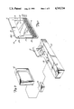
- FIG. 1 is a perspective view of an embodiment of an information encoded projector slide in accordance with the present invention.
- FIG. 2 is a schematic view of a read/write system for use with the information projector slide shown in FIG. 1.
- FIG. 3 is a schematic view of a read-only system for use with the information projector slide shown in FIG. 1.
- FIG. 4 is a schematic view of a read/write system having an optical image projection system for use with the information projector slide shown in FIG. 1.
- FIG. 5 is a schematic view of a read/write system having a video projection system for use with the information projector slide shown in FIG. 1.
- FIG. 6 is a schematic view of a read/write system having a cropping system for viewing selected portions of a photographic image for use with the information projector slide shown in FIG. 1.
- projector slide 10 includes a planar frame member 12, having an opening or window 14 in its central portion and at least one border 16 adjacent to window 14.
- projector slide 10 is a flat, square frame 12 having four borders 16, 17, 18, and 19. It is preferred that frame 12 be constructed from a rigid and economical material, such as cardboard or plastic.
- Window 14 is of sufficient size to mount a photographic image (not shown) in any suitable manner.
- Projector slide 10 includes a first surface 21A and a second surface 21B.
- a photographic film image 20 (not shown) is secured in window 14 between surfaces 21A and 21B in any usual or preferred manner.
- projector slide 10 is a standard 35 mm projector slide.
- Magnetic medium 22 is used for storing desired information, particularly alpha-numeric data. As illustrated in FIG. 1 magnetic medium 22 can include one or more tracks, such as 23, 24 and 25, for storing various data. Various methods of affixing magnetic medium 22 to projector slide 10 are within the scope of this invention.
- magnetic medium 22 can be adhesively affixed to border 16.
- magnetic medium 22 can be thermally bonded to border 16.
- magnetic medium 22 can be applied in a liquid or semi-liquid state by wiping, spraying or brushing the surface of border 16. The liquid is allowed to cure in known manner to form a flat, dry magnetic medium 22.
- Encoded data includes, but is not limited to, a description of the photographic film image, date of the image, name of photographer, type of film used, a classification code, and cropping or other processing information.
- Magnetic medium 22 permits information to be stored concurrently with the projector slide. Such information can be used for cataloging and indexing the projector slides. For example, a random quantity of information encoded projector slides can be loaded in an apparatus capable of reading magnetic medium 22. The apparatus can sort and store the projector slides as desired.
- a read/write system 30 for utilizing information projector slide 10 as described above is illustrated in the schematic diagram of FIG. 2.
- a carriage 31 for receiving projector slide 10 includes a slot track 32. Border 16 of projector slide 10 is positioned in slot 32. In FIG. 2, second surface 21B of projector slide 10 is shown. Magnetic medium 22 is on opposite side 21A (not shown) of projector slide 10 on border 16.
- a first or write head 34 is mounted on carriage 31 so that head 34 can be in contact with or very closely spaced from magnetic medium 22 of projector slide 10.
- a second or read head 36 is mounted on carriage 31 so that head 36 can be in contact with or very closely spaced from magnetic medium 22.
- Read and write heads 34 and 36 are magnetic pickup heads and are interfaced with read/write electronic circuitry 38.
- Read/write system 30 also includes a tachometer counter 33 which is interfaced to circuitry 38. As projector slide 10 passes by write head 34, roller 35 contacts surface 21B, and data representative of the speed at which projector slide 10 is moving is provided to circuitry 38. This speed data is utilized by circuitry 38 to properly write data onto magnetic medium 22.
- Circuitry 38 is interfaced with a keyboard 40 and a data display monitor 42. It will be understood that carriage 31, write and read heads 34 and 36, electronic circuitry 38, keyboard 40 and display monitor 42 can be packaged into an integral housing (not shown) as desired.
- information to be encoded or written onto projector slide 10 is typed on keyboard 40 and simultaneously displayed on monitor 42. Selected information can be entered into predetermined fields (not shown). Each field has a selected length. The sum of all fields equals the storage capacity of magnetic medium 22.
- projector slide 10 is positioned in slot 32. As magnetic medium 22 passes in contact with write head 34, the information is digitally encoded thereon. Projector slide 10 continues through slot 32 so that medium 22 makes contact with read head 36. Read head 36 detects the encoded information.
- system 30 include a verification system.
- Memory within circuitry 38 compares the encoded information written to medium 22 with information read by read head 36 to assure that it was properly encoded.
- a signal such as a single audio beep, can issue from system 30 to indicate conformation.
- An indication such as a visual display provided through monitor 42 can issue to indicate an improper write operation. Additional passes through slot 32 are made until the information is properly encoded or written onto projector slide 10.
- Read head 36 also permits system 30 to detect previously encoded information, and display this information on monitor 42. Furthermore, previously encoded data on medium 22 can also be erased and replaced with new data.
- a read-only system is illustrated in the schematic diagram of FIG. 3.
- carriage 31 includes a slot 32 for receiving projector slide 10.
- Read head 36 mounted on carriage 31, is interfaced with read-only electronics 39 which in turn is interfaced with data display monitor 42.
- read head 34 encoded information from medium 22 is read by read head 34, decoded by electronics 39, and displayed on monitor 42.
- Electronics 39 can also be interfaced with a printer (not shown) or computer (not shown) so that displayed data can be printed or stored, respectively, as desired.
- FIG. 4 A third preferred embodiment of the data storage and retrieval system of the present invention, system 60, is illustrated in FIG. 4.
- a slidable carriage 44 is actuated by an electric drive system 46.
- Drive system 46 moves projector slide 10 across write and/or read heads 34 and 36, respectively, in response to commands from keyboard 40 through controller 38.
- Drive system 46 includes an electric motor 47, a take-up spool 48 mounted on an output shaft 47A of motor 47, and a guide wire 49 connected at a first end to spool 48 and at a second end to carriage 44.
- Other systems for moving projector slide 10 can also be used.
- write head 34, read head 36, read/write electronics 38, keyboard 40 and data display monitor 42 are provided for encoding information on and displaying information from magnetic medium 22.
- a verification system as described above for read/write system 30 can also be included.
- System 60 includes an optical reflection system 51 for viewing an image from photographic slide 10.
- a slight source such as lamp 52 is provided on one side of projector slide 10 so that an image mounted therein is projected to a mirror 54 and reflected to a screen 56.
- a diffuser 57 is provided between light source 52 and projector slide 10.
- a lens 58 is provided between projector slide 10 and mirror 54. Diffuser 57 and lens 58 are utilized to focus the image projected on screen 56 in known manner. It will be understood that the elements of system 60 can be packaged into an integral housing (not shown) if desired.
- FIG. 5 A fourth preferred embodiment of the present invention, system 70, is illustrated in FIG. 5.
- write and read heads 34 and 36 are positioned near a carriage 44 to respectively encode information on and read information from, magnetic medium 22 of projector slide 10.
- a video projection system 72 concurrently displays an image from a projector slide 10 with information from magnetic medium 22.
- a video camera 74 receives an image from projector slide 10 created by a light source such as lamp 52, diffuser 57 and lens 58.
- a signal is sent from camera 74 to mixer/controller 75.
- Drive system 46 is also interfaced with keyboard 40 through mixer/controller 75, as shown, and functions in a manner previously described.
- Mixer/controller 75 is also interfaced with keyboard 40 to encode information onto, and read information from, magnetic medium 22 through write head 34 and read head 36, respectively.
- Mixer/controller 75 is interfaced with monitor 42 for simultaneous display of the image mounted in and information encoded on projector slide 10. It is preferred that camera 74, mixer 75 and monitor 42 are configured to invert negatives to positive images. This is of significance, since it permits the more frequently used photographic print (which produces color reversal negatives) for slides as well. It will be understood that the elements of system 70 can be packaged into an integral housing (not shown) if desired.
- a fifth preferred embodiment of the present invention, system 80 includes cropping system 82.
- Projector slide 10 is mounted in a slide holder 83.
- a vertical cropping drive 84 includes a motor 85 and a threaded spool or screw 86 associated with holder 83 so that rotation of screw 86 positions holder 83 to a desired vertical orientation.
- a horizontal cropping drive 88 having a motor 89 and a threaded screw 90 associated with holder 83 is provided to position projector slide 10 at a desired horizontal orientation.
- a light source such as lamp 52 illuminates projector slide 10 through diffuser 57 and lens 58 to video camera 74.
- Video camera 74 includes a zoom lens 77 actuated by a zoom drive 92.
- Video camera 74 can be interfaced with a conventional color inverter 94.
- Color inverter 94 permits the viewer to see negatives and true colors, therefore allowing system 80 to be used with either photographic slide positives or negatives.
- a cropping and color controller 96 is also included within system 80. As shown, vertical cropping drive 84, horizontal cropping drive 88 and zoom drive 92 are interfaced with controller 96. Cropping drives 84 and 88 are actuated by a joystick 97A, and zoom drive 92 is actuated by a dial 97B. Color inverter 94 is also interfaced with controller 96 and controlled by a joystick 98A and dial 98B. Joystick 98A selects hue and tint, while dial 98B selects density. As used herein, color inversion is the process of accepting a signal or set of signals proportional to and representative of the relative intensity of a narrow band light source of specified wavelength and producing an output signal or set of signals inversely proportional to the input. It is to be understood that controls 97A and 97B for cropping drives 84 and 88 can be provided in a separate housing from color inverter controls 98A and 98B. Furthermore, other control devices are within the scope of the present invention.
- An image from camera 74 is received by electronics 78.
- Electronics 78 is interfaced with keyboard 40.
- the image and information from projector slide 10 can be simultaneously displayed on monitor 42. Once settings for cropping and color are selected, such information is encoded onto magnetic medium 22 of projector slide 10.
- the selected settings are encoded through electronics 78, color inverter 94 and write head 34 in a manner described above.
- the T.V. video slide/negative projector system 80 provides greater personal satisfaction with photography, as enlarging and recropping in the comforts of the home on the T.V. monitor are available. Encoding of this recropped image is recorded on the magnetic medium 12 on the projector slide 10 and can be used by the properly equipped photo lab to provide reprints and enlargements of this newly formatted picture.
- the encloded enlargement and X, Y location data can allow reshowing on the T.V. monitor 42 of the reformatted picture instead of the original image.
- Several reformatted pictures from the same projector slide 10 are possible, if the data is encoded for each.
- magnetically stored data is used to identify and X-Y movement and enlargement of the reformatted image. This information will be used by the device itself when reshowing the reformatted image, and by modified enlarging printers used by photofinishers to generate reformatted prints and enlargements.
- the magnetic data has many other uses as well, such as recording of color correction data, instruction information for photofinishers regarding size and number of desired prints, subject identification, date, location and retrieval data.
- the entire system leads itself to automatic storage and retrieval systems of mass data stored photographically on 2 ⁇ 2" slide mounts, with video and hard copy output capabilities.
Abstract
Description
Claims (14)
Priority Applications (4)
| Application Number | Priority Date | Filing Date | Title |
|---|---|---|---|
| US06/866,214 US4765734A (en) | 1986-05-22 | 1986-05-22 | Digitally encoded alpha-numeric projector slide and systems for using the same |
| EP87304195A EP0246799B1 (en) | 1986-05-22 | 1987-05-12 | Digitally encoded alpha-numeric projector slide and systems for using the same |
| DE8787304195T DE3769845D1 (en) | 1986-05-22 | 1987-05-12 | ALPHANUMERICALLY DIGITALLY CODED DIAPOSITIVE AND SYSTEMS FOR USE THEREOF. |
| JP62125636A JPS6332529A (en) | 1986-05-22 | 1987-05-22 | Numerically coded character/numeral projector slide and system using the same |
Applications Claiming Priority (1)
| Application Number | Priority Date | Filing Date | Title |
|---|---|---|---|
| US06/866,214 US4765734A (en) | 1986-05-22 | 1986-05-22 | Digitally encoded alpha-numeric projector slide and systems for using the same |
Publications (1)
| Publication Number | Publication Date |
|---|---|
| US4765734A true US4765734A (en) | 1988-08-23 |
Family
ID=25347171
Family Applications (1)
| Application Number | Title | Priority Date | Filing Date |
|---|---|---|---|
| US06/866,214 Expired - Lifetime US4765734A (en) | 1986-05-22 | 1986-05-22 | Digitally encoded alpha-numeric projector slide and systems for using the same |
Country Status (4)
| Country | Link |
|---|---|
| US (1) | US4765734A (en) |
| EP (1) | EP0246799B1 (en) |
| JP (1) | JPS6332529A (en) |
| DE (1) | DE3769845D1 (en) |
Cited By (18)
| Publication number | Priority date | Publication date | Assignee | Title |
|---|---|---|---|---|
| US5159363A (en) * | 1988-12-02 | 1992-10-27 | Eastman Kodak Company | Optical system |
| US5227821A (en) * | 1987-04-30 | 1993-07-13 | Nview Corporation | Liquid crystal display for projection systems |
| US5255029A (en) * | 1987-04-30 | 1993-10-19 | Nview Corporation | Liquid crystal display for projection systems |
| US5467153A (en) * | 1991-03-01 | 1995-11-14 | Data Fit International | Apparatus for automatically digitizing photographic slides |
| US5541680A (en) * | 1995-02-09 | 1996-07-30 | Fromm; Wayne G. | Slide projector assembly |
| US5555042A (en) * | 1994-10-06 | 1996-09-10 | Eastman Kodak Company | Apparatus for automatically feeding slides into a film scanner |
| US5738428A (en) * | 1996-12-31 | 1998-04-14 | Eastman Kodak Company | Formatting projector |
| US5743609A (en) * | 1996-12-31 | 1998-04-28 | Eastman Kodak Company | Method and apparatus for preparing photographic film units having image frame associated encoded information |
| US5743615A (en) * | 1996-12-31 | 1998-04-28 | Eastman Kodak Company | Film slides having encoded data and methods for preparing film slides |
| US5751399A (en) * | 1996-12-31 | 1998-05-12 | Eastman Kodak Company | Film slides having data windows |
| US5803565A (en) * | 1996-12-31 | 1998-09-08 | Eastman Kodak Company | Orienting projector |
| US5845160A (en) * | 1997-05-08 | 1998-12-01 | Eastman Kodak Company | Method for transferring a recording from a sound index print and player-transfer apparatus |
| US5934777A (en) * | 1997-05-08 | 1999-08-10 | Eastman Kodak Company | Method for sequencing film image presentations and film image sequencer |
| US5944404A (en) * | 1997-07-18 | 1999-08-31 | Eastman Kodak Company | Defined orientation slide projector and slides |
| US5949524A (en) * | 1997-07-18 | 1999-09-07 | Eastman Kodak Company | Film segment printing system and method |
| US5995138A (en) * | 1996-07-25 | 1999-11-30 | Image Science Corporation | Transparency film digitizer peripheral and transparency film image management and communication system for internet |
| US6079832A (en) * | 1996-12-31 | 2000-06-27 | Eastman Kodak Company | Annotation displaying projector |
| US7857454B2 (en) | 2006-12-13 | 2010-12-28 | Mattel, Inc. | Image Projecting device |
Families Citing this family (16)
| Publication number | Priority date | Publication date | Assignee | Title |
|---|---|---|---|---|
| JPS6087923A (en) * | 1983-10-20 | 1985-05-17 | Mitsubishi Heavy Ind Ltd | Discharge device of wire rod terminal crop |
| US4965575A (en) * | 1988-10-07 | 1990-10-23 | Eastman Kodak Company | Data alignment circuit and method for self-clocking encoded data |
| US4965626A (en) * | 1988-10-07 | 1990-10-23 | Eastman Kodak Company | Printing and makeover process for magnetically encodable film with dedicated magnetic tracks |
| US5021820A (en) * | 1988-10-07 | 1991-06-04 | Eastman Kodak Company | Order entry process for magnetically encodable film with dedicated magnetic tracks |
| US4965627A (en) * | 1988-10-07 | 1990-10-23 | Eastman Kodak Company | Film information exchange system using dedicated magnetic tracks on film with virtual data indentifiers |
| US5006873A (en) * | 1988-10-07 | 1991-04-09 | Eastman Kodak Company | Implicit mid roll interrupt protection code for camera using dedicated magnetic tracks on film |
| EP0437543B1 (en) * | 1988-10-07 | 1995-05-24 | Eastman Kodak Company | Film information exchange system using dedicated magnetic tracks on film |
| US5029313A (en) * | 1988-10-07 | 1991-07-02 | Eastman Kodak Company | Photofinishing apparatus with film information exchange system using dedicated magnetic tracks on film |
| US4977419A (en) * | 1988-10-07 | 1990-12-11 | Eastman Kodak Company | Self-clocking encoding/decoding film information exchange system using dedicated magnetic tracks on film |
| US4975732A (en) * | 1988-10-07 | 1990-12-04 | Eastman Kodak Company | Finishing process for magnetically encodable film with dedicated magnetic tracks |
| CH679082A5 (en) * | 1989-02-03 | 1991-12-13 | Agilolf Prof Dr Lamperstorfer | |
| FR2745096B1 (en) * | 1996-02-21 | 1998-05-15 | Preulier Robert | METHOD AND APPARATUS FOR VIEWING AND / OR RECORDING PHOTOGRAPHIC SELECTIONS FROM NEGATIVES OR SLIDES |
| US9921461B1 (en) | 2017-09-22 | 2018-03-20 | Spin Master Ltd. | Clip for mounting external device to electronic device |
| US10295898B2 (en) | 2016-06-17 | 2019-05-21 | Moonlite World Inc. | Image projection device |
| US10298727B2 (en) | 2016-06-17 | 2019-05-21 | Spin Master Ltd. | Clip for mounting external device to electronic device |
| US10571793B2 (en) | 2016-06-17 | 2020-02-25 | Moonlite World Inc. | Image projection device |
Citations (25)
| Publication number | Priority date | Publication date | Assignee | Title |
|---|---|---|---|---|
| US3095034A (en) * | 1962-01-03 | 1963-06-25 | John P Francis | Retractable windshield awning |
| US3176580A (en) * | 1962-02-08 | 1965-04-06 | Bell & Howell Co | Sound tape and picture slide holder |
| US3238842A (en) * | 1962-06-14 | 1966-03-08 | Airequipt Inc | Transparency holder with sliding sound tape |
| US3350983A (en) * | 1965-08-18 | 1967-11-07 | Martin E Gerry | Slide retainer and sound track frame |
| US3352204A (en) * | 1963-04-29 | 1967-11-14 | Staar Marcel Jules Helene | Frame for supporting a transparency and sound reproducing material |
| US3509651A (en) * | 1966-01-03 | 1970-05-05 | Itek Corp | Optical viewer |
| US3594076A (en) * | 1968-06-10 | 1971-07-20 | Marvin Glass & Associates | Audio-slide projector |
| US3691312A (en) * | 1970-05-25 | 1972-09-12 | Polaroid Corp | Tape recording apparatus and system having a very thin cassette |
| GB1312679A (en) * | 1969-07-15 | 1973-04-04 | Reiter W | Form-card intended to receive written matter and provided with at least one magnetic track and at least one holder to receive transparencies |
| US3779637A (en) * | 1969-06-14 | 1973-12-18 | M Otsuboj | Slide attachment with a sounding mechanism |
| US3784296A (en) * | 1972-06-19 | 1974-01-08 | L Davis | Coding means for photographic slide apparatus |
| US3790266A (en) * | 1970-10-24 | 1974-02-05 | Fuji Photo Film Co Ltd | Microfiche projecting apparatus |
| US3807851A (en) * | 1972-06-06 | 1974-04-30 | Minnesota Mining & Mfg | Slide identification clip |
| US3876297A (en) * | 1972-06-06 | 1975-04-08 | Minnesota Mining & Mfg | Slide identification |
| US3879117A (en) * | 1972-10-04 | 1975-04-22 | Jean J Damlamian | Apparatus for the visual display of inscriptions on transparencies |
| US3883238A (en) * | 1973-12-26 | 1975-05-13 | Panayotis C Dimitracopoulos | Audiovisual slides and apparatus |
| US3943563A (en) * | 1969-03-17 | 1976-03-09 | Lemelson Jerome H | System and method for recording and reproducing video information on a card |
| US4014604A (en) * | 1973-10-01 | 1977-03-29 | Kalart Victor Corporation | Sound slide |
| JPS5241523A (en) * | 1975-09-29 | 1977-03-31 | Toshiba Corp | Electroacoustic converter |
| US4102569A (en) * | 1976-09-07 | 1978-07-25 | Kalart Victor Corporation | Sound slide |
| US4223463A (en) * | 1978-09-11 | 1980-09-23 | Tapecon, Inc. | Recording tape carrier |
| US4270853A (en) * | 1979-03-21 | 1981-06-02 | West Electric Company, Ltd. | Sound-recording instant-printing film and camera therefor |
| JPS58111108A (en) * | 1981-12-24 | 1983-07-02 | Comput Services Corp | Issuing method for magnetic card |
| US4554591A (en) * | 1983-09-19 | 1985-11-19 | Polaroid Corporation | Reproducible image and information bearing record |
| US4592042A (en) * | 1983-02-16 | 1986-05-27 | Lemelson Jerome H | Record card transducing apparatus and method |
Family Cites Families (3)
| Publication number | Priority date | Publication date | Assignee | Title |
|---|---|---|---|---|
| BE844336A (en) * | 1976-07-20 | 1976-11-16 | DISPLAY DEVICE FOR SLIDE CASSETTES | |
| JPS5897036A (en) * | 1981-12-04 | 1983-06-09 | Fuji Xerox Co Ltd | Microfilm supporting card |
| DE3434508A1 (en) * | 1984-09-20 | 1986-03-27 | Helmut 8000 München Aleritsch | Television transparency viewer |
-
1986
- 1986-05-22 US US06/866,214 patent/US4765734A/en not_active Expired - Lifetime
-
1987
- 1987-05-12 DE DE8787304195T patent/DE3769845D1/en not_active Expired - Fee Related
- 1987-05-12 EP EP87304195A patent/EP0246799B1/en not_active Expired - Lifetime
- 1987-05-22 JP JP62125636A patent/JPS6332529A/en active Pending
Patent Citations (25)
| Publication number | Priority date | Publication date | Assignee | Title |
|---|---|---|---|---|
| US3095034A (en) * | 1962-01-03 | 1963-06-25 | John P Francis | Retractable windshield awning |
| US3176580A (en) * | 1962-02-08 | 1965-04-06 | Bell & Howell Co | Sound tape and picture slide holder |
| US3238842A (en) * | 1962-06-14 | 1966-03-08 | Airequipt Inc | Transparency holder with sliding sound tape |
| US3352204A (en) * | 1963-04-29 | 1967-11-14 | Staar Marcel Jules Helene | Frame for supporting a transparency and sound reproducing material |
| US3350983A (en) * | 1965-08-18 | 1967-11-07 | Martin E Gerry | Slide retainer and sound track frame |
| US3509651A (en) * | 1966-01-03 | 1970-05-05 | Itek Corp | Optical viewer |
| US3594076A (en) * | 1968-06-10 | 1971-07-20 | Marvin Glass & Associates | Audio-slide projector |
| US3943563A (en) * | 1969-03-17 | 1976-03-09 | Lemelson Jerome H | System and method for recording and reproducing video information on a card |
| US3779637A (en) * | 1969-06-14 | 1973-12-18 | M Otsuboj | Slide attachment with a sounding mechanism |
| GB1312679A (en) * | 1969-07-15 | 1973-04-04 | Reiter W | Form-card intended to receive written matter and provided with at least one magnetic track and at least one holder to receive transparencies |
| US3691312A (en) * | 1970-05-25 | 1972-09-12 | Polaroid Corp | Tape recording apparatus and system having a very thin cassette |
| US3790266A (en) * | 1970-10-24 | 1974-02-05 | Fuji Photo Film Co Ltd | Microfiche projecting apparatus |
| US3807851A (en) * | 1972-06-06 | 1974-04-30 | Minnesota Mining & Mfg | Slide identification clip |
| US3876297A (en) * | 1972-06-06 | 1975-04-08 | Minnesota Mining & Mfg | Slide identification |
| US3784296A (en) * | 1972-06-19 | 1974-01-08 | L Davis | Coding means for photographic slide apparatus |
| US3879117A (en) * | 1972-10-04 | 1975-04-22 | Jean J Damlamian | Apparatus for the visual display of inscriptions on transparencies |
| US4014604A (en) * | 1973-10-01 | 1977-03-29 | Kalart Victor Corporation | Sound slide |
| US3883238A (en) * | 1973-12-26 | 1975-05-13 | Panayotis C Dimitracopoulos | Audiovisual slides and apparatus |
| JPS5241523A (en) * | 1975-09-29 | 1977-03-31 | Toshiba Corp | Electroacoustic converter |
| US4102569A (en) * | 1976-09-07 | 1978-07-25 | Kalart Victor Corporation | Sound slide |
| US4223463A (en) * | 1978-09-11 | 1980-09-23 | Tapecon, Inc. | Recording tape carrier |
| US4270853A (en) * | 1979-03-21 | 1981-06-02 | West Electric Company, Ltd. | Sound-recording instant-printing film and camera therefor |
| JPS58111108A (en) * | 1981-12-24 | 1983-07-02 | Comput Services Corp | Issuing method for magnetic card |
| US4592042A (en) * | 1983-02-16 | 1986-05-27 | Lemelson Jerome H | Record card transducing apparatus and method |
| US4554591A (en) * | 1983-09-19 | 1985-11-19 | Polaroid Corporation | Reproducible image and information bearing record |
Non-Patent Citations (5)
| Title |
|---|
| "Preserve Your Film Memories on Videocassettes", Synchronics, Holiday 1985, p. 8. |
| Brochure, Card Data Format, two pages. * |
| IBM Tech Disclosure Bulletin, vol. 21, #9, "Audio Recording on Magnetic Stripe Documents". |
| IBM Tech Disclosure Bulletin, vol. 21, 9, Audio Recording on Magnetic Stripe Documents . * |
| Preserve Your Film Memories on Videocassettes , Synchronics, Holiday 1985, p. 8. * |
Cited By (19)
| Publication number | Priority date | Publication date | Assignee | Title |
|---|---|---|---|---|
| US5227821A (en) * | 1987-04-30 | 1993-07-13 | Nview Corporation | Liquid crystal display for projection systems |
| US5255029A (en) * | 1987-04-30 | 1993-10-19 | Nview Corporation | Liquid crystal display for projection systems |
| US5404185A (en) * | 1987-04-30 | 1995-04-04 | Nview Corporation | Liquid crystal display for projection systems |
| US5159363A (en) * | 1988-12-02 | 1992-10-27 | Eastman Kodak Company | Optical system |
| US5467153A (en) * | 1991-03-01 | 1995-11-14 | Data Fit International | Apparatus for automatically digitizing photographic slides |
| US5555042A (en) * | 1994-10-06 | 1996-09-10 | Eastman Kodak Company | Apparatus for automatically feeding slides into a film scanner |
| US5541680A (en) * | 1995-02-09 | 1996-07-30 | Fromm; Wayne G. | Slide projector assembly |
| US5995138A (en) * | 1996-07-25 | 1999-11-30 | Image Science Corporation | Transparency film digitizer peripheral and transparency film image management and communication system for internet |
| US5743609A (en) * | 1996-12-31 | 1998-04-28 | Eastman Kodak Company | Method and apparatus for preparing photographic film units having image frame associated encoded information |
| US5743615A (en) * | 1996-12-31 | 1998-04-28 | Eastman Kodak Company | Film slides having encoded data and methods for preparing film slides |
| US5751399A (en) * | 1996-12-31 | 1998-05-12 | Eastman Kodak Company | Film slides having data windows |
| US5803565A (en) * | 1996-12-31 | 1998-09-08 | Eastman Kodak Company | Orienting projector |
| US5738428A (en) * | 1996-12-31 | 1998-04-14 | Eastman Kodak Company | Formatting projector |
| US6079832A (en) * | 1996-12-31 | 2000-06-27 | Eastman Kodak Company | Annotation displaying projector |
| US5845160A (en) * | 1997-05-08 | 1998-12-01 | Eastman Kodak Company | Method for transferring a recording from a sound index print and player-transfer apparatus |
| US5934777A (en) * | 1997-05-08 | 1999-08-10 | Eastman Kodak Company | Method for sequencing film image presentations and film image sequencer |
| US5944404A (en) * | 1997-07-18 | 1999-08-31 | Eastman Kodak Company | Defined orientation slide projector and slides |
| US5949524A (en) * | 1997-07-18 | 1999-09-07 | Eastman Kodak Company | Film segment printing system and method |
| US7857454B2 (en) | 2006-12-13 | 2010-12-28 | Mattel, Inc. | Image Projecting device |
Also Published As
| Publication number | Publication date |
|---|---|
| JPS6332529A (en) | 1988-02-12 |
| EP0246799A1 (en) | 1987-11-25 |
| DE3769845D1 (en) | 1991-06-13 |
| EP0246799B1 (en) | 1991-05-08 |
Similar Documents
| Publication | Publication Date | Title |
|---|---|---|
| US4765734A (en) | Digitally encoded alpha-numeric projector slide and systems for using the same | |
| US4974096A (en) | Photofinishing process with film-to-video printer using dedicated magnetic tracks on film | |
| US5072253A (en) | Ordering and recording information system for business and greeting cards | |
| US5132715A (en) | Camera apparatus with pseudo-format film encodement | |
| JPH095937A (en) | Photograph camera, system related to photograph camera belt,manufacture of photograph film cartridge and processing method of photograph film belt | |
| US5757468A (en) | Method and apparatus for producing photographic prints with sound indicia thereon | |
| US4972068A (en) | Retrieval apparatus readily adaptable for use with various types of recording media | |
| US5179409A (en) | Film holder for storing processed photographic film | |
| EP0437533B1 (en) | Photofinishing process with film-to-video player using dedicated magnetic tracks on film | |
| US4647982A (en) | Image display apparatus capable of starting display of a new image in response to designation thereof prior to completion of display of a previously designated image | |
| US4671648A (en) | Image data processing apparatus | |
| US5838464A (en) | System and method for scanning images contained on a strip of photosensitive film | |
| CA1306298C (en) | Digitally encoded alpha-numeric projector slide and systems for using the same | |
| US5743609A (en) | Method and apparatus for preparing photographic film units having image frame associated encoded information | |
| US5601956A (en) | Film unit with lens and development method thereof | |
| US4633305A (en) | Method of recording image signals of photographic pictures | |
| US5743615A (en) | Film slides having encoded data and methods for preparing film slides | |
| US5803565A (en) | Orienting projector | |
| JPH0545714A (en) | Photographic film | |
| US5075705A (en) | Methods of an apparatus for providing printed photographs with a border | |
| US6079832A (en) | Annotation displaying projector | |
| US5738428A (en) | Formatting projector | |
| EP0692731A1 (en) | Method and apparatus for controlling exposure format | |
| JPH047493B2 (en) | ||
| US5173731A (en) | Recording apparatus |
Legal Events
| Date | Code | Title | Description |
|---|---|---|---|
| AS | Assignment |
Owner name: PAKON, INC., 6121 BAKER ROAD, MINNETONKA, MINNESOT Free format text: ASSIGNMENT OF ASSIGNORS INTEREST.;ASSIGNORS:TRUC, JAMES A.;HOONSBEEN, GARY A.;REEL/FRAME:004807/0145 Effective date: 19860514 Owner name: PAKON, INC., 6121 BAKER ROAD, MINNETONKA, MINNESOT Free format text: ASSIGNMENT OF ASSIGNORS INTEREST;ASSIGNORS:TRUC, JAMES A.;HOONSBEEN, GARY A.;REEL/FRAME:004807/0145 Effective date: 19860514 |
|
| STCF | Information on status: patent grant |
Free format text: PATENTED CASE |
|
| CC | Certificate of correction | ||
| FEPP | Fee payment procedure |
Free format text: PAYOR NUMBER ASSIGNED (ORIGINAL EVENT CODE: ASPN); ENTITY STATUS OF PATENT OWNER: SMALL ENTITY |
|
| FPAY | Fee payment |
Year of fee payment: 4 |
|
| FPAY | Fee payment |
Year of fee payment: 8 |
|
| FPAY | Fee payment |
Year of fee payment: 12 |
|
| FEPP | Fee payment procedure |
Free format text: PAYOR NUMBER ASSIGNED (ORIGINAL EVENT CODE: ASPN); ENTITY STATUS OF PATENT OWNER: SMALL ENTITY Free format text: PAYER NUMBER DE-ASSIGNED (ORIGINAL EVENT CODE: RMPN); ENTITY STATUS OF PATENT OWNER: SMALL ENTITY |
|
| AS | Assignment |
Owner name: EASTMAN KODAK COMPANY, NEW YORK Free format text: ASSIGNMENT OF ASSIGNORS INTEREST;ASSIGNOR:PAKON, INC.;REEL/FRAME:012025/0542 Effective date: 20010206 |