US4766497A - IF circuit with reduced sound attenuation for cable signals - Google Patents
IF circuit with reduced sound attenuation for cable signals Download PDFInfo
- Publication number
- US4766497A US4766497A US07/046,962 US4696287A US4766497A US 4766497 A US4766497 A US 4766497A US 4696287 A US4696287 A US 4696287A US 4766497 A US4766497 A US 4766497A
- Authority
- US
- United States
- Prior art keywords
- trap
- cable
- signals
- tuner
- signal
- Prior art date
- Legal status (The legal status is an assumption and is not a legal conclusion. Google has not performed a legal analysis and makes no representation as to the accuracy of the status listed.)
- Expired - Lifetime
Links
Images
Classifications
-
- H—ELECTRICITY
- H04—ELECTRIC COMMUNICATION TECHNIQUE
- H04N—PICTORIAL COMMUNICATION, e.g. TELEVISION
- H04N5/00—Details of television systems
- H04N5/44—Receiver circuitry for the reception of television signals according to analogue transmission standards
- H04N5/60—Receiver circuitry for the reception of television signals according to analogue transmission standards for the sound signals
- H04N5/62—Intercarrier circuits, i.e. heterodyning sound and vision carriers
Definitions
- This invention relates generally to cable-ready television receivers and specifically to an intermediate frequency (IF) circuit that is alterable for operation with cable signals and off-air signals.
- IF intermediate frequency
- the IF circuits process a video carrier of 45.75 MHz, an audio carrier of 41.25 MHz and a 3.58 MHz color subcarrier, which is modulated on the video or picture carrier.
- the audio carrier when detecting the IF video carrier signal the audio carrier must be suppressed to a low amplitude with respect to the video carrier to avoid cross modulation between carriers, especially between the audio carrier and the color subcarrier. Since the audio carrier must also be recovered, however, it cannot be suppressed to the point that its detection is impaired.
- Conventional IF circuits include an adjustable audio carrier trap which, by appropriate tuning of its frequency and impedance at resonance, tailors the response characteristic of the IF amplifier circuit at the audio carrier frequency to that which is desired.
- a single coaxial cable carries a multiplicity of TV channels of differing frequencies.
- the amplifiers at the cable head-end or transmitting station are of necessity wide-band, which enhances the probability of interference between the various carriers present in the TV signal.
- most cable systems reduce the audio carrier amplitude with respect to the video carrier amplitude to a greater degree than is their practice with respect to over-the-air signals, hereinafter referred to as "off-air" signals.
- the audio carrier is from 7 to 10 db below the picture carrier, whereas in a cable system the audio carrier may be from 17 to 20 db below the picture carrier.
- SAW surface acoustic wave
- Another object of the invention is to provide an IF circuit that is usable with off-air and cable signals.
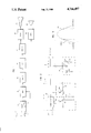
- FIG. 1 is a simplified block diagram of a television receiver constructed in accordance with the invention
- FIG. 2 is a schematic diagram of a portion of the receiver of FIG. 1;
- FIG. 3 represents a graph showing the prior art IF response curve and that of the invention.
- a tuner means 10 is supplied with input signals from either an antenna 12 or a cable 14.
- the separate antenna and cable input signals may be applied, through a switch, to a suitable input of tuner means 10, or as shown, may be applied to separate inputs and coupled internally to appropriate tuning circuits of tuner means 10.
- Tuner means 10 is shown as including a block 16, labelled SEL (for selector), which should be understood to include a suitable switching means for arranging the tuning circuits in tuner 10 to receive signals from either antenna 12 or cable 14.
- Selector 16 may be mechanically operated or, in accordance with more recent techniques, be voltage controllable circuits coupled to suitable varactor type tuning diodes.
- Tuner means 10 also includes well-known signal tuning and mixing circuitry for receiving a plurality of TV signal frequencies and converting them to a single IF output signal that is supplied to a trap 18 constructed in accordance with the invention.
- Trap 18 is shown connected to selector 16 in tuner means 10 for purposes to be explained.
- the output of trap 18 is supplied to a SAW IF circuit 20, which in turn, supplies an amplifier 22.
- the output of amplifier 22 is applied to a synchronous detector 24 that has outputs supplying a video circuit 26 for driving a cathode ray tube (CRT) 28 and an audio circuit 30 for driving a loudspeaker 32.
- CTR cathode ray tube
- tuner means 10 and trap 18 are indicated by the respectively identified dashed line boxes.
- a block 34 labelled TUNING CIRCUITS is intended to include circuitry for tuning the TV channel frequencies and developing a common IF output signal therefrom.
- Selector 16 is schematically depicted as a double pole, double throw switch with a one pole labelled 16a and another pole labelled 16b, both poles being operated together. Pole 16a is connected to ground and is switchable between a pair of terminals labelled "cable" and "TV” for enabling operation of appropriate circuitry within tuning circuits 34 (not shown) for selectively processing signals from the antenna or cable inputs.
- Pole 16b is connectable between a pair of taps on a voltage divider consisting of resistors 13, 15 and 17 serially connected between a source of B+ voltage and ground.
- the junction of resistor 13 and 15 represents the TV position
- the junction of resistors 15 and 17 represents the cable position.
- Pole 16b is connected, through a resistor 38, to the junction of a varactor diode 40 and a capacitor 42 in a trap 18. It will be seen that when switch pole 16b is in the TV position, a higher voltage is impressed across varactor diode 40 than is the case when switch 16b is in the cable position.
- the other terminal of capacitor 42 is connected to the junction of a capacitor 44 and the parallel connection of a capacitor 46 and adjustable coil 48.
- Varactor diode 40 exhibits a capacitance across its terminals that is a function of the DC voltage applied across it. Therefore, the capacitance of diode 40 and the serially connected capacitance of capacitor 42 cooperate with capacitors 44 and 46 and coil 48 to complete trap 18.
- trap 18 When in the TV position, trap 18 is tuned to the audio carrier frequency and is effective to tailor the frequency response to the IF signal to reduce the audio carrier with respect to the video and color carriers. Reference to FIG. 3 will better illustrate this.
- the solid curve is the IF response produced with sound trap 18 tuned to the audio carrier frequency and being fully effective as is the case for an off-air signal (selector 16 in the TV position).
- the response at the audio carrier frequency point (labelled S) is indicated as being down from those at the color (C) and video or picture (P) carrier frequency points.
- the audio carrier frequency response is about 25 db down from that at the color and picture carrier frequencies.
- the dashed line curve for the IF response which corresponds to selector 16 being in the cable position, shows the response at the audio carrier frequency (S) as being only slightly down from the response at frequencies corresponding to the color and video carriers. In practice, it is about 8 db down. This dashed line curve corresponds to trap 18 being detuned from the audio carrier frequency in accordance with the invention.
- varactor diode 40 In operation, with selector 16 in the TV position, varactor diode 40 is biased by B+ and the voltage divided comprising resistors 13, 15 and 17 to exhibit a low capacity which in conjunction with the remaining elements in trap 18, tunes trap 18 to the audio carrier frequency. Trap 18 thus functions normally to absorb energy at the audio carrier frequency from the IF signal from tuner means 10. Upon movement of selector 16 to the cable position, varactor diode 40 is biased to a high capacity condition to alter the frequency response of trap 18. Specifically, its frequency response is changed such that it does not absorb energy at the audio carrier frequency. Trap 18 is effectively disabled which results in the frequency response indicated by the dashed line curve.
- the transmitted audio signal is significantly reduced with respect to the picture or video carrier as above-described and consequently, the 920 KHz interference problem is substantially reduced.
- the omission of trap 18 does not deteriorate performance of the TV receiver in this respect. Its omission, however, does enhance the ability of the IF amplifier, in particular a SAW IF amplifier, to effectively operate with the reduced level audio carrier in the cable signal by enabling it to be amplified to a substantially greater degree.
- the invention provides optimum performance for both off-air and cable signals in a TV receiver. Since the switching of the trap is tied to the selector in the tuner means, the benefits of the invention are obtained without requiring any additional knowledge or effort by the viewer. It will also be appreciated that the technique of switching the trap need not be restricted to that illustrated, the invention contemplating any suitable means for switching.
Abstract
Description
Claims (4)
Priority Applications (1)
| Application Number | Priority Date | Filing Date | Title |
|---|---|---|---|
| US07/046,962 US4766497A (en) | 1987-05-06 | 1987-05-06 | IF circuit with reduced sound attenuation for cable signals |
Applications Claiming Priority (1)
| Application Number | Priority Date | Filing Date | Title |
|---|---|---|---|
| US07/046,962 US4766497A (en) | 1987-05-06 | 1987-05-06 | IF circuit with reduced sound attenuation for cable signals |
Publications (1)
| Publication Number | Publication Date |
|---|---|
| US4766497A true US4766497A (en) | 1988-08-23 |
Family
ID=21946316
Family Applications (1)
| Application Number | Title | Priority Date | Filing Date |
|---|---|---|---|
| US07/046,962 Expired - Lifetime US4766497A (en) | 1987-05-06 | 1987-05-06 | IF circuit with reduced sound attenuation for cable signals |
Country Status (1)
| Country | Link |
|---|---|
| US (1) | US4766497A (en) |
Cited By (9)
| Publication number | Priority date | Publication date | Assignee | Title |
|---|---|---|---|---|
| US4974085A (en) * | 1989-05-02 | 1990-11-27 | Bases Burke Institute, Inc. | Television signal substitution |
| US20020197975A1 (en) * | 2001-05-18 | 2002-12-26 | Resonext Communications, Inc. | Method for calibrating a DC offset cancellation level for direct conversion receivers |
| US6509777B2 (en) | 2001-01-23 | 2003-01-21 | Resonext Communications, Inc. | Method and apparatus for reducing DC offset |
| US6606489B2 (en) | 2001-02-14 | 2003-08-12 | Rf Micro Devices, Inc. | Differential to single-ended converter with large output swing |
| US6748204B1 (en) | 2000-10-17 | 2004-06-08 | Rf Micro Devices, Inc. | Mixer noise reduction technique |
| US6778022B1 (en) | 2001-05-17 | 2004-08-17 | Rf Micro Devices, Inc. | VCO with high-Q switching capacitor bank |
| US6801585B1 (en) | 2000-10-16 | 2004-10-05 | Rf Micro Devices, Inc. | Multi-phase mixer |
| US6807406B1 (en) | 2000-10-17 | 2004-10-19 | Rf Micro Devices, Inc. | Variable gain mixer circuit |
| US7302011B1 (en) | 2002-10-16 | 2007-11-27 | Rf Micro Devices, Inc. | Quadrature frequency doubling system |
Citations (5)
| Publication number | Priority date | Publication date | Assignee | Title |
|---|---|---|---|---|
| US4109280A (en) * | 1976-06-28 | 1978-08-22 | Massachusetts Institute Of Technology | Television interface device |
| US4312016A (en) * | 1979-02-02 | 1982-01-19 | Jerrold Electronics Corporation | Television signal switching apparatus |
| US4348691A (en) * | 1980-11-10 | 1982-09-07 | Blonder-Tongue Laboratories, Inc. | Master antenna subscription television system and the like |
| US4499495A (en) * | 1982-07-26 | 1985-02-12 | Zenith Electronics Corporation | Switching diplexer for single antenna input television receivers |
| US4633316A (en) * | 1984-11-14 | 1986-12-30 | Zenith Electronics Corporation | Stable low cost 4.5 MHz remodulator |
-
1987
- 1987-05-06 US US07/046,962 patent/US4766497A/en not_active Expired - Lifetime
Patent Citations (5)
| Publication number | Priority date | Publication date | Assignee | Title |
|---|---|---|---|---|
| US4109280A (en) * | 1976-06-28 | 1978-08-22 | Massachusetts Institute Of Technology | Television interface device |
| US4312016A (en) * | 1979-02-02 | 1982-01-19 | Jerrold Electronics Corporation | Television signal switching apparatus |
| US4348691A (en) * | 1980-11-10 | 1982-09-07 | Blonder-Tongue Laboratories, Inc. | Master antenna subscription television system and the like |
| US4499495A (en) * | 1982-07-26 | 1985-02-12 | Zenith Electronics Corporation | Switching diplexer for single antenna input television receivers |
| US4633316A (en) * | 1984-11-14 | 1986-12-30 | Zenith Electronics Corporation | Stable low cost 4.5 MHz remodulator |
Cited By (10)
| Publication number | Priority date | Publication date | Assignee | Title |
|---|---|---|---|---|
| US4974085A (en) * | 1989-05-02 | 1990-11-27 | Bases Burke Institute, Inc. | Television signal substitution |
| US6801585B1 (en) | 2000-10-16 | 2004-10-05 | Rf Micro Devices, Inc. | Multi-phase mixer |
| US6748204B1 (en) | 2000-10-17 | 2004-06-08 | Rf Micro Devices, Inc. | Mixer noise reduction technique |
| US6807406B1 (en) | 2000-10-17 | 2004-10-19 | Rf Micro Devices, Inc. | Variable gain mixer circuit |
| US6509777B2 (en) | 2001-01-23 | 2003-01-21 | Resonext Communications, Inc. | Method and apparatus for reducing DC offset |
| US6606489B2 (en) | 2001-02-14 | 2003-08-12 | Rf Micro Devices, Inc. | Differential to single-ended converter with large output swing |
| US6778022B1 (en) | 2001-05-17 | 2004-08-17 | Rf Micro Devices, Inc. | VCO with high-Q switching capacitor bank |
| US20020197975A1 (en) * | 2001-05-18 | 2002-12-26 | Resonext Communications, Inc. | Method for calibrating a DC offset cancellation level for direct conversion receivers |
| US6941121B2 (en) | 2001-05-18 | 2005-09-06 | Rf Micro Devices, Inc. | Method for calibrating a DC offset cancellation level for direct conversion receivers |
| US7302011B1 (en) | 2002-10-16 | 2007-11-27 | Rf Micro Devices, Inc. | Quadrature frequency doubling system |
Similar Documents
| Publication | Publication Date | Title |
|---|---|---|
| US5146337A (en) | Using a first IF of 43.5 MHZ or less in an FM radio in a television tuner | |
| JP2791839B2 (en) | Television receiver | |
| US5146338A (en) | Fixed rf agc of a television tuner for fm reception in a television receiver | |
| US6351294B1 (en) | Television signal receiving tuner capable of receiving FM broadcasting signals without being affected by other interference signals | |
| US4766497A (en) | IF circuit with reduced sound attenuation for cable signals | |
| US5054117A (en) | Tunable UHF filter for switchable VHF/UHF receiver | |
| EP0584717B1 (en) | Television receiver tuning circuit | |
| KR100211413B1 (en) | Fm trap for a television tuner permitting both tv and fm reception through the same tuner | |
| KR100211412B1 (en) | Interrupting the video if signal path during fm radio mode in a television receiver | |
| US3495031A (en) | Variable q i.f. amplifier circuit for a television receiver | |
| KR100211620B1 (en) | First if filter with fixed second half-if trap for use in an radio in a television | |
| JP2791840B2 (en) | Television receiver | |
| KR890000648B1 (en) | Television sound signal receiver | |
| KR100211411B1 (en) | Information radio reception in a television receiver by synthesizing only center frequency | |
| HU208205B (en) | Multi-system sound signal processing unit for multi-system television receiver | |
| JP2002359788A (en) | Television receiver | |
| US3135827A (en) | Television receiver sound improvement apparatus | |
| US4547805A (en) | Television AFC system usable with offset carrier frequencies | |
| JP2575493B2 (en) | Variable bandpass filter | |
| KR970004910Y1 (en) | Suppression circuit of high frequency module for interference of intermediate frequency range | |
| JPS6247281A (en) | Video intermediate frequency amplifier | |
| JPH01155780A (en) | Television-cum-fm broadcasting receiver | |
| JPH04238409A (en) | Filter circuit | |
| KR20010075983A (en) | Tuner in the image process system | |
| JPH0775410B2 (en) | Integrated electronic tuning tuner |
Legal Events
| Date | Code | Title | Description |
|---|---|---|---|
| AS | Assignment |
Owner name: ZENITH ELECTRONICS CORPORATION, 1000 MILWAUKEE AVE Free format text: ASSIGNMENT OF ASSIGNORS INTEREST.;ASSIGNORS:BANACH, FRANK G.;HAERLE, JAMES G.;TAIT, DAVID S.;REEL/FRAME:004891/0590 Effective date: 19870506 Owner name: ZENITH ELECTRONICS CORPORATION, ILLINOIS Free format text: ASSIGNMENT OF ASSIGNORS INTEREST;ASSIGNORS:BANACH, FRANK G.;HAERLE, JAMES G.;TAIT, DAVID S.;REEL/FRAME:004891/0590 Effective date: 19870506 |
|
| STCF | Information on status: patent grant |
Free format text: PATENTED CASE |
|
| FPAY | Fee payment |
Year of fee payment: 4 |
|
| AS | Assignment |
Owner name: FIRST NATIONAL BANK OF CHICAGO, THE Free format text: SECURITY INTEREST;ASSIGNOR:ZENITH ELECTRONICS CORPORATION A CORP. OF DELAWARE;REEL/FRAME:006187/0650 Effective date: 19920619 |
|
| AS | Assignment |
Owner name: ZENITH ELECTRONICS CORPORATION Free format text: RELEASED BY SECURED PARTY;ASSIGNOR:FIRST NATIONAL BANK OF CHICAGO, THE (AS COLLATERAL AGENT).;REEL/FRAME:006243/0013 Effective date: 19920827 |
|
| FEPP | Fee payment procedure |
Free format text: PAYOR NUMBER ASSIGNED (ORIGINAL EVENT CODE: ASPN); ENTITY STATUS OF PATENT OWNER: LARGE ENTITY |
|
| FPAY | Fee payment |
Year of fee payment: 8 |
|
| FPAY | Fee payment |
Year of fee payment: 12 |