US4770508A - Conversion lens releasably attached behind master lens - Google Patents
Conversion lens releasably attached behind master lens Download PDFInfo
- Publication number
- US4770508A US4770508A US06/898,314 US89831486A US4770508A US 4770508 A US4770508 A US 4770508A US 89831486 A US89831486 A US 89831486A US 4770508 A US4770508 A US 4770508A
- Authority
- US
- United States
- Prior art keywords
- lens
- conversion
- curvature
- radius
- positive
- Prior art date
- Legal status (The legal status is an assumption and is not a legal conclusion. Google has not performed a legal analysis and makes no representation as to the accuracy of the status listed.)
- Expired - Lifetime
Links
Images


Classifications
-
- G—PHYSICS
- G02—OPTICS
- G02B—OPTICAL ELEMENTS, SYSTEMS OR APPARATUS
- G02B15/00—Optical objectives with means for varying the magnification
- G02B15/02—Optical objectives with means for varying the magnification by changing, adding, or subtracting a part of the objective, e.g. convertible objective
- G02B15/04—Optical objectives with means for varying the magnification by changing, adding, or subtracting a part of the objective, e.g. convertible objective by changing a part
- G02B15/08—Optical objectives with means for varying the magnification by changing, adding, or subtracting a part of the objective, e.g. convertible objective by changing a part by changing the rear part
Definitions
- This invention relates to conversion lenses, and more particularly to conversion lenses releasably attached on the image side of a master lens system to change the focal length of the entire system. Still more particularly, it relates to conversion lenses of reduced size while still permitting the imaging performance to be improved, suited to be used in photographic cameras or video cameras.
- Japanese Laid-Open Patent Application No. Sho 54-97423 proposes a rear conversion method in which the conversion lens is inserted into a space after the master lens system has been axially moved forward to change the focal length of the entire system. But, because the number of lens elements is as many as six, the total length of the lens tends to increase.
- Japanese Laid-Open Patent Application No. Sho 58-195817 discloses a conversion lens of relative small size in which the rear conversion method is also employed and, while a shortening of the back focal distance of the entire system is achieved, the focal length of the entire system is changed. But, the change of the focal length is 1.25 times. So the magnification change rate was not always sufficient.
- the refractive power of the conversion lens may be strengthened. This method had drawbacks that too much aberration was produced, and particularly spherical aberration and Petzval sum were increased so that correction of curvature of field became difficult to perform.
- Japanese Laid-Open Patent Application No. Sho 56-94318 filed by the assignee of the present invention discloses a rear conversion lens comprising two lens elements of positive and negative powers. The photographs taken with this lens attached to the master lens when enlarged in a high rate, sometimes impressed the viewer with a loss of the image quality.
- An object of the invention is to provide a conversion lens employing the rear conversion method and having a good optical performance at a high magnification change rate while minimizing the size of the entire system.
- a concomitant object of the invention is that among the various aberrations which give influence to the image quality, good correction of particularly spherical aberration is achieved.
- FIG. 1A is an optical section view of a master lens
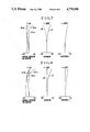
- FIG. 1B is a graph of its aberration curves.
- FIG. 2 is a graph for explaining the amount of deviation of an aspherical surface.
- FIG. 3 is an optical section view of a first embodiment of the rear conversion lens according to the present invention attached to the master lens.
- FIG. 4, FIG. 5, FIG. 6, FIG. 7 and FIG. 8 are graphs of the aberration curves of first, second, third, fourth and fifth embodiments respectively.
- FIG. 9 is an optical section view of another master lens.
- FIG. 10 is a graph of the aberration curves of the master lens of FIG. 9.
- FIG. 11 is an optical section view of a sixth embodiment of the rear conversion lens attached to the master lens of FIG. 9.
- FIG. 12 is a graph of the aberration curves of the sixth embodiment.
- FIG. 1A and FIG. 9 there are shown respectively the master lens systems 1 and 2 to which the conversion lenses of the invention are to be attached.
- FIG. 3 there is shown a combined system of the master lens 1 of FIG. 1A and a numerical example 1 of the conversion lens of the invention.
- FIG. 11 shows another combined system of the master lens 2 of FIG. 9 and a numerical example 6 of the conversion lens of the invention.
- the conversion lens comprises two lenses, or a first lens of positive refractive power and a second lens of negative refractive power, whereby the overall refractive power is made negative, and at least one lens surface is made aspherical with such a figuring that the positive refractive power becomes stronger as a whole from the center of the lens surface to the margin.
- the aspherical surface is formed to have such a shape that the positive refractive power becomes as a whole stronger toward the marginal portion.
- the positive refractive power is strengthened, and when it is the lens surface of the negative refractive power, the negative refractive power is weakened, so that the spherical aberration is well corrected.
- the distance from the first lens surface of the master lens system to the image plane is made to change the magnification.
- the conversion lens according to the present invention is achieved by satisfying the above-described various conditions. But, to properly correct particularly spherical aberration, the shape of the aspherical surface as depicted in FIG. 2 is set so as to satisfy the following condition: ##EQU1## where ⁇ X is the difference between the aspherical surface A and a reference spherical surface RS at a point of incidence of a marginal ray L of light flux that determines the F-number of the master lens system at full open aperture on the aspherical surface A. In other words, the difference between the aspherical surface and the extended surface of the sphere of the paraxial region, and f is the focal length of the entire system including the master lens system.
- n1 and n2 are the refractive powers of the glasses of the first and second lenses respectively.
- the conversion lens according to the present invention has a negative refractive power as a whole, when the conversion lens is attached, the Petzval sum is caused to increase to the negative direction. So, for the first lens, a glass having a refractive index n1 is selected, and for the second lens, a glass having a large refractive index n2 is selected, while the inequality of condition (2) is satisfied, thereby the Petzval sum is reduced as a whole.
- r4 is the radius of curvature of the rear surface RA of the second lens
- f R if the focal length of the conversion lens. It should be pointed out here that it is preferable to decrease the upper limit till 2.8.
- the last lens surface RA of the conversion lens is made to become near to the concentric circle toward the diaphragm, thereby the astigmatism is well corrected.
- the radius of curvature of the lens surface RA grows stronger beyond the lower limit of the inequalities of condition (3), the astigmatism increases to the negative direction.
- the radius of curvature weakens beyond the upper limit, other off-axis aberrations including astigmatism become difficult to correct in good balance.
- the aspherical surface having the above-stated condition may be applied to two or more of the lens surfaces of the first and second lenses.
- each lens surface of the first and second lenses is formed by a shape that turns the concave surface toward the diaphragm in order to correct particularly off-axis aberrations in good balance.
- focusing with the conversion lens attached may be performed either by moving the master lens system forward, or by moving the conversion lens rearward.
- the master lens systems to be described later are shown to be of the Tesaar type and the triplet type. But, the master lens system may be of any other types such as the Gauss type and telephoto type.
- Ri or ri is the radius of curvature of the i-th lens surface counting from the front
- Di or di is the i-th lens thickness or air separation counting from the front
- Ni or ni, and vi are respectively the refractive index and Abbe number of the glass of the i-th lens element counting from front.
- d1 is the distance from the diaphragm to the first lens surface of the conversion lens.
- a conversion lens that enables the size of the entire system to be reduced while still permitting a great increase in the magnification change rate and good optical performance can be achieved.
Abstract
Description
n2-n1>0.18 (2)
0.8<r4/f.sub.R <3.2 (3)
______________________________________
Numerical Example 1 of the Master Lens System
F = 100.00  FNO = 1:2.86  2ω = 59.34°
______________________________________
R1 = 34.59 D1 = 10.72 N1 = 1.77250
                                  ν1 = 49.6
R2 = 109.66
           D2 = 3.09
R3 = -158.80
           D3 = 5.27  N2 = 1.72151
                                  ν2 = 29.2
R4 = 32.75 D4 = 3.55
R5 = 260.16
           D5 = 2.05  N3 = 1.58144
                                  ν3 = 40.7
R6 = 38.41 D6 = 8.58  N4 = 1.80610
                                  ν4 = 40.9
R7 = -77.98
           D7 = 4.21
R8 = ∞ (Stop)
______________________________________
______________________________________
Numerical Example 2 of the Master Lens System
F = 100.00  FNO = 1:3.60  2ω= 65.15°
______________________________________
R1 = 30.75 D1 = 10.45 N1 = 1.77250
                                  ν1 = 49.6
R2 = 95.84 D2 = 2.53
R3 = -163.49
           D3 = 2.94  N2 = 1.69895
                                  ν2 = 30.1
R4 = 30.22 D4 = 5.68
R5 = 137.11
           D5 = 5.21  N3 = 1.80610
                                  ν3 = 40.9
R6 = -74.98
           D6 = 3.53
R7 = ∞ (Stop)
______________________________________
______________________________________
Numerical Example 1
F = 151.43  FNO = 1:4.33  2ω = 41.23°
______________________________________
           d1 = 5.27
r*1 = -693.98
           d2 = 5.68  n1 = 1.6727 ν1 = 32.1
r2 = -40.84
           d3 = 2.56
r3 = -35.34
           d4 = 3.16  n2 = 1.8830 ν2 = 40.8
r4 = -329.99
______________________________________
Aspherical Coefficients
                    A = 0
for the Surface r*1:
                    B = 3.907 × 10.sup.-7
                    C = 2.214 × 10.sup.-9
                    D = 1.730 × 10.sup.-12
                    E = -1.173 × 10.sup.-14
______________________________________
______________________________________
Numerical Example 2
F = 151.4  FNO = 1:4.33  2ω= 41.24°
______________________________________
           d1 = 5.27
r1 = -2010.91
           d2 = 6.11  n1 = 1.5927 ν1 = 35.3
r*2 = -36.54
           d3 = 2.28
r3 = -32.66
           d4 = 3.16  n2 = 1.8410 ν2 = 43.2
r4 = -272.83
______________________________________
Aspherical Coefficients
                    A = 0
for the Surface r*2:
                    B = -5.540 × 10.sup.-7
                    C = -4.067 × 10.sup.-9
                    D = 8.787 × 10.sup.-12
                    E = -1.641 × 10.sup.-15
______________________________________
______________________________________
Numerical Example 3
F = 148.77  FNO = 1:4.25  2ω = 41.91°
______________________________________
           d1 = 5.27
r1 = -664.81
           d2 = 6.58  n1 = 1.6727 ν1 = 32.1
r2 = -40.50
           d3 = 2.63
r*3 = -35.53
           d4 = 3.16  n2 = 1.8830 ν2 = 40.8
r4 = -348.20
______________________________________
Aspherical Coefficients
                    A = 0
for the Surface r*3:
                    B = 2.282 × 10.sup.-7
                    C = 2.702 × 10.sup.-9
                    D = -7.885 × 10.sup.-12
                    E = 1.318 × 10.sup.-14
______________________________________
______________________________________
Numerical Example 4
F = 152.41  FNO = 1:4.36  2ω = 41.0°
______________________________________
           d1 = 5.27
r1 = -997.49
           d2 = 6.11  n1 = 1.5927 ν1 = 35.3
r2 = -35.93
           d3 = 2.36
r3 = -33.04
           d4 = 3.16  n2 = 1.8410 ν2 = 43.2
r*4 = -310.37
______________________________________
Aspherical Coefficients
                    A = 0
for the Surface r*4:
                    B = -2.859 × 10.sup.-7
                    C = -1.651 × 10.sup.-9
                    D = 5.726 × 10.sup.-12
                    E = -1.126 × 10.sup.-14
______________________________________
______________________________________
Numerical Example 5
F = 149.16  FNO = 1:4.26  2ω = 41.81°
______________________________________
           d1 = 5.27
r*1 = -724.96
           d2 = 5.68  n1 = 1.6727 ν1 = 32.1
r2 = -40.82
           d3 = 2.56
r*3 = -35.39
           d4 = 3.16  n2 = 1.8830 ν2 = 40.8
r4 = -320.91
______________________________________
Aspherical Coefficients
For the Surface r*1 For the Surface r*3
______________________________________
A = 0               A = 0
B = 3.381 × 10.sup.-7
                    B = 9.225 × 10.sup.-8
C = 1.417 × 10.sup.-9
                    C = 4.169 × 10.sup.-10
D = 1.181 × 10.sup.-12
                    D = 1.621 × 10.sup.-13
E = -1.203 × 10.sup.-14
                    E = 8.726 × 10.sup.-17
______________________________________
______________________________________
Numerical Example 6
F = 142.74  FNO = 1:5.14  2ω = 48.08°
______________________________________
           d1 = 5.89
r1 = -546.63
           d2 = 6.54  n1 = 1.5927 ν1 = 35.3
r2 = -38.36
           d3 = 2.65
r3 = -34.99
           d4 = 3.53  n2 = 1.8410 ν2 = 43.2
r*4 = -229.11
______________________________________
Aspherical Coefficients
                    A = 0
for the Surface r*4:
                    B = -1.765 × 10.sup.-7
                    C = -9.791 × 10.sup.-10
                    D = -5.048 × 10.sup.-13
                    E = 6.717 × 10.sup.-16
______________________________________
TABLE 1 ______________________________________ Numerical Factors inConditions Example Aspherical 1 2 3 No. Surface |ΔX|/f n2 - n1 r4/f.sub.R ______________________________________ 1 r1 1.127 × 10.sup.-4 0.2103 1.946 2 r2 1.278 × 10.sup.-4 0.2483 1.602 3 r3 4.032 × 10.sup.-4 0.2103 2.013 4 r4 3.390 × 10.sup.-5 0.2483 1.850 5 r1 8.490 × 10.sup.-5 0.2103 1.842 r3 1.326 × 10.sup.-5 6 r4 8.768 × 10.sup.-6 0.2483 1.186 ______________________________________
Claims (9)
0.8<r4/f.sub.R <3.2
n2-n1>0.18
Applications Claiming Priority (2)
| Application Number | Priority Date | Filing Date | Title |
|---|---|---|---|
| JP60184473A JPS6243613A (en) | 1985-08-22 | 1985-08-22 | Converter lens |
| JP60-184473 | 1985-08-22 |
Publications (1)
| Publication Number | Publication Date |
|---|---|
| US4770508A true US4770508A (en) | 1988-09-13 |
Family
ID=16153778
Family Applications (1)
| Application Number | Title | Priority Date | Filing Date |
|---|---|---|---|
| US06/898,314 Expired - Lifetime US4770508A (en) | 1985-08-22 | 1986-08-20 | Conversion lens releasably attached behind master lens |
Country Status (2)
| Country | Link |
|---|---|
| US (1) | US4770508A (en) |
| JP (1) | JPS6243613A (en) |
Cited By (10)
| Publication number | Priority date | Publication date | Assignee | Title |
|---|---|---|---|---|
| US4900141A (en) * | 1988-04-01 | 1990-02-13 | Nikon Corporation | Rear conversion lens |
| US5086355A (en) * | 1986-12-27 | 1992-02-04 | Minolta Camera Kabushiki Kaisha | Focal length changeable lens system |
| US5113287A (en) * | 1988-05-16 | 1992-05-12 | Canon Kabushiki Kaisha | Compact zoom lens with positive power front lens group and negative power rear lens group |
| US5282040A (en) * | 1991-05-07 | 1994-01-25 | Itzhak Sapir | Apparatus for operating a film camera |
| US5574523A (en) * | 1991-10-23 | 1996-11-12 | Canon Kabushiki Kaisha | Camera capable of varying size of image plane |
| US5699202A (en) * | 1995-07-14 | 1997-12-16 | Fuji Photo Optical Co., Ltd. | Imaging lens |
| US6404487B1 (en) | 1998-09-16 | 2002-06-11 | Canon Kabushiki Kaisha | Light measuring device |
| CN102654631A (en) * | 2011-03-02 | 2012-09-05 | 佳能株式会社 | Camera apparatus and image pickup apparatus including the same |
| US10175458B2 (en) | 2016-11-24 | 2019-01-08 | Largan Precision Co., Ltd. | Photographing lens assembly, image capturing unit and electronic device |
| US11169365B2 (en) * | 2019-04-08 | 2021-11-09 | Canon Kabushiki Kaisha | Rear attachment lens and image pickup optical system using the same |
Families Citing this family (3)
| Publication number | Priority date | Publication date | Assignee | Title |
|---|---|---|---|---|
| JP2690765B2 (en) * | 1988-12-28 | 1997-12-17 | オリンパス光学工業株式会社 | Rear converter lens |
| JP3241672B2 (en) | 1998-07-31 | 2001-12-25 | 三菱電機株式会社 | Interference wave detection device and interference wave detection method |
| CN113238349B (en) * | 2017-08-17 | 2022-06-07 | 浙江舜宇光学有限公司 | Optical imaging lens |
Citations (3)
| Publication number | Priority date | Publication date | Assignee | Title |
|---|---|---|---|---|
| US4443067A (en) * | 1979-10-01 | 1984-04-17 | Polaroid Corporation | Zone focusing optical system |
| US4477154A (en) * | 1981-06-27 | 1984-10-16 | Canon Kabushiki Kaisha | Photographic objective |
| DE3504626A1 (en) * | 1984-02-16 | 1985-08-29 | Olympus Optical Co., Ltd., Tokio/Tokyo | PHOTOGRAPHIC LENS WITH FOCAL LENGTH CHANGEABLE BY LENS REPLACEMENT |
-
1985
- 1985-08-22 JP JP60184473A patent/JPS6243613A/en active Pending
-
1986
- 1986-08-20 US US06/898,314 patent/US4770508A/en not_active Expired - Lifetime
Patent Citations (3)
| Publication number | Priority date | Publication date | Assignee | Title |
|---|---|---|---|---|
| US4443067A (en) * | 1979-10-01 | 1984-04-17 | Polaroid Corporation | Zone focusing optical system |
| US4477154A (en) * | 1981-06-27 | 1984-10-16 | Canon Kabushiki Kaisha | Photographic objective |
| DE3504626A1 (en) * | 1984-02-16 | 1985-08-29 | Olympus Optical Co., Ltd., Tokio/Tokyo | PHOTOGRAPHIC LENS WITH FOCAL LENGTH CHANGEABLE BY LENS REPLACEMENT |
Cited By (13)
| Publication number | Priority date | Publication date | Assignee | Title |
|---|---|---|---|---|
| US5086355A (en) * | 1986-12-27 | 1992-02-04 | Minolta Camera Kabushiki Kaisha | Focal length changeable lens system |
| US4900141A (en) * | 1988-04-01 | 1990-02-13 | Nikon Corporation | Rear conversion lens |
| US5113287A (en) * | 1988-05-16 | 1992-05-12 | Canon Kabushiki Kaisha | Compact zoom lens with positive power front lens group and negative power rear lens group |
| US5282040A (en) * | 1991-05-07 | 1994-01-25 | Itzhak Sapir | Apparatus for operating a film camera |
| US6134389A (en) * | 1991-10-23 | 2000-10-17 | Canon Kabushiki Kaisha | Camera capable of varying size of image plane |
| US5574523A (en) * | 1991-10-23 | 1996-11-12 | Canon Kabushiki Kaisha | Camera capable of varying size of image plane |
| US5699202A (en) * | 1995-07-14 | 1997-12-16 | Fuji Photo Optical Co., Ltd. | Imaging lens |
| US6404487B1 (en) | 1998-09-16 | 2002-06-11 | Canon Kabushiki Kaisha | Light measuring device |
| CN102654631A (en) * | 2011-03-02 | 2012-09-05 | 佳能株式会社 | Camera apparatus and image pickup apparatus including the same |
| US20120224095A1 (en) * | 2011-03-02 | 2012-09-06 | Canon Kabushiki Kaisha | Camera apparatus and image pickup apparatus including the same |
| US8873153B2 (en) * | 2011-03-02 | 2014-10-28 | Canon Kabushiki Kaisha | Camera apparatus and image pickup apparatus including the same |
| US10175458B2 (en) | 2016-11-24 | 2019-01-08 | Largan Precision Co., Ltd. | Photographing lens assembly, image capturing unit and electronic device |
| US11169365B2 (en) * | 2019-04-08 | 2021-11-09 | Canon Kabushiki Kaisha | Rear attachment lens and image pickup optical system using the same |
Also Published As
| Publication number | Publication date |
|---|---|
| JPS6243613A (en) | 1987-02-25 |
Similar Documents
| Publication | Publication Date | Title |
|---|---|---|
| US5260833A (en) | Zoom lens system | |
| US4772106A (en) | Compact zoom lens system | |
| US5076677A (en) | Zoom lens | |
| US4260223A (en) | Lens system for photographing objects from infinity to a very short distance | |
| US4394071A (en) | Lens system with fill-in lens | |
| US4596447A (en) | Conversion type varifocal lens system | |
| JP3302072B2 (en) | High-performance shooting lens | |
| US4770508A (en) | Conversion lens releasably attached behind master lens | |
| US5233474A (en) | Wide-angle lens system | |
| US4542961A (en) | Triplet type objective | |
| US4235521A (en) | Photographic lens system | |
| US3992085A (en) | Large aperture wide angle lens system employing an aspherical surface | |
| US4364641A (en) | Wide angle zoom lens | |
| JP3331011B2 (en) | Small two-group zoom lens | |
| US4643536A (en) | Rear conversion lens | |
| KR100189069B1 (en) | Small wide angle photo lens | |
| JP3268824B2 (en) | Small two-group zoom lens | |
| US5446590A (en) | High eye point type viewfinder optical system | |
| US4695134A (en) | Compact photographic lens | |
| JP3234618B2 (en) | Large aperture medium telephoto lens | |
| JP3331228B2 (en) | Bright wide-angle lens | |
| JPH05346542A (en) | Small-sized two-group zoom lens | |
| US4019810A (en) | Photographic wide angle lens | |
| JPH07318798A (en) | Photographic lens | |
| JPH073503B2 (en) | Wide-angle lens with long back focus |
Legal Events
| Date | Code | Title | Description |
|---|---|---|---|
| AS | Assignment |
Owner name: CANON KABUSHIKI KAISHA, 3-30-2, SHIMOMARUKO, OHTA- Free format text: ASSIGNMENT OF ASSIGNORS INTEREST.;ASSIGNORS:YAMADA, YASUYUKI;SATO, YASUHISA;NAKAYAMA, HIROKI;AND OTHERS;REEL/FRAME:004592/0871 Effective date: 19860811 Owner name: CANON KABUSHIKI KAISHA,JAPAN Free format text: ASSIGNMENT OF ASSIGNORS INTEREST;ASSIGNORS:YAMADA, YASUYUKI;SATO, YASUHISA;NAKAYAMA, HIROKI;AND OTHERS;REEL/FRAME:004592/0871 Effective date: 19860811 |
|
| STCF | Information on status: patent grant |
Free format text: PATENTED CASE |
|
| CC | Certificate of correction | ||
| FPAY | Fee payment |
Year of fee payment: 4 |
|
| FPAY | Fee payment |
Year of fee payment: 8 |
|
| FEPP | Fee payment procedure |
Free format text: PAYER NUMBER DE-ASSIGNED (ORIGINAL EVENT CODE: RMPN); ENTITY STATUS OF PATENT OWNER: LARGE ENTITY Free format text: PAYOR NUMBER ASSIGNED (ORIGINAL EVENT CODE: ASPN); ENTITY STATUS OF PATENT OWNER: LARGE ENTITY |
|
| FPAY | Fee payment |
Year of fee payment: 12 |