US4771345A - Reproducing apparatus - Google Patents
Reproducing apparatus Download PDFInfo
- Publication number
- US4771345A US4771345A US06/815,039 US81503985A US4771345A US 4771345 A US4771345 A US 4771345A US 81503985 A US81503985 A US 81503985A US 4771345 A US4771345 A US 4771345A
- Authority
- US
- United States
- Prior art keywords
- speed
- tape
- audio information
- signal
- reproduction
- Prior art date
- Legal status (The legal status is an assumption and is not a legal conclusion. Google has not performed a legal analysis and makes no representation as to the accuracy of the status listed.)
- Expired - Lifetime
Links
Images


Classifications
-
- H—ELECTRICITY
- H04—ELECTRIC COMMUNICATION TECHNIQUE
- H04N—PICTORIAL COMMUNICATION, e.g. TELEVISION
- H04N9/00—Details of colour television systems
- H04N9/79—Processing of colour television signals in connection with recording
- H04N9/80—Transformation of the television signal for recording, e.g. modulation, frequency changing; Inverse transformation for playback
- H04N9/802—Transformation of the television signal for recording, e.g. modulation, frequency changing; Inverse transformation for playback involving processing of the sound signal
-
- G—PHYSICS
- G11—INFORMATION STORAGE
- G11B—INFORMATION STORAGE BASED ON RELATIVE MOVEMENT BETWEEN RECORD CARRIER AND TRANSDUCER
- G11B27/00—Editing; Indexing; Addressing; Timing or synchronising; Monitoring; Measuring tape travel
- G11B27/005—Reproducing at a different information rate from the information rate of recording
-
- G—PHYSICS
- G11—INFORMATION STORAGE
- G11B—INFORMATION STORAGE BASED ON RELATIVE MOVEMENT BETWEEN RECORD CARRIER AND TRANSDUCER
- G11B2220/00—Record carriers by type
- G11B2220/90—Tape-like record carriers
Definitions
- the present invention relates to a reproducing apparatus for a video tape recorder or the like and more particularly, to a reproducing apparatus for reproducing speech sounds at a speed faster than a normal reproduction speed.
- the sound signal reproduced simultaneously with the image signal when the tape speed was n times as fast as the normal speed, became a frequency n times the normal sound signal. As the speed of the sound has been increased n times, the sound becomes extremely hard to hear.
- VSC variable speech control
- an essential object of the present invention is to control the tape speed so that the variable speech control is performed during the video search operation. The reproducing sound will then become rapid enough so as to be easily hear.
- the tape speed is desired to be controlled to be not more than two times the normal speed. In other words, while the tape speed is required to be fast due to the searching operation the tape speed cannot be too fast if it is to easily be heard. Accordingly, approximately 1.5 times as fast as normal is an optimum tape speed.
- the reproducing apparatus is composed of image reproducing means, sound reproducing means, reproducing speed switching means, reproducing time compression (VSC) means for sound signals, switching means which switches the sound signals not effected by the VSC means and the sound signals effected by the VSC means to output them.
- VSC reproducing time compression
- a magnetic record reproducing apparatus is provided with a tape delivery means for causing the magnetic tape to run, a speed detecting means for detecting the tape running speed, a phase detecting means which detects control signals recorded on the magnetic tape for the phase control of the magnetic tape and the image reproducing means, a controlling means which transmits given signals to the tape delivering means in accordance with the detecting signals from the speed detecting means and the phase detecting means, the controlling means is provided with compensating means which compensates the detecting signal from the speed detecting means and the detecting signal from the phase detecting means to given values.
- a rotary head with a head disposed on the diagonal line of the rotary drum being a double azimuth head, switching means for selecting the reproducing output produced by each of the heads, switch control means which drives the switch means in accordance with the given order are provided.
- the switching operation is effected into one of the double azimuth heads in a vertical blanking period by the switching means.
- FIG. 1 is a circuit diagram showing the schematic construction in one embodiment of the present invention
- FIGS. 2 through 8 are respective signals waveform charts for explaining the function of each portion of the circuit construction of FIG. 1;
- FIG. 9 is a circuit diagram showing the details of a capstan servo-circuit in the circuit construction of FIG. 1;
- FIG. 10 is a plan view of a rotary head in FIG. 1;
- FIG. 11 is a view showing the head track on the magnetic tape by the rotary head
- FIG. 12 is a control block diagram for controlling image signals from the rotary head in FIG. 10.
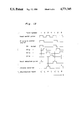
- FIG. 13 is a time chart showing the operation of the control block diagram of FIG. 12.
- FIG. 1 shows an embodiment of the present invention.
- a capstan servo-circuit 1 controls a capstan motor 4, by a control signal from a control head 2 and a speed signal from a capstan 3, to make the tape 5 have a constant speed.
- a rotary head 6 reproduces the image track of the tape 5. Switching and outputting operations and performed in a given order by a head SW circuit 7. It is converted into image signals by an image reproducing circuit 8 and is outputted in image.
- An audio head 9 reproduces the audio track of the tape 5, which is amplified by an audio AMP 10. As a sound switch SW11 is connected onto the side a during the normal reproducing operation, the output of the AMP 10 is provided as it is in sound through the sound switch SW11.
- the capstan servo-circuit 1 changes the operation by a signal which is 1.5 times the normal speed so that the speed of the tape 5 may become 1.5 times as fast as the speed at the normal reproduction.
- the detailed description of the circuit 1 will be given later.
- the head SW circuit 7 changes the operation by 1.5 times the normal speed signal, which will be destructed later in detail.
- the sound switch SW is switched onto the side b by a signal which is 1.5 times as fast as normal.
- the output of the audio AMP 10 is adapted to be sound-outputted in the sound signals effected by the reproduction time compression means 13.
- the reproduction time compression means 13 will be described hereinafter. Assume that the standard reproduction waveform of the audio AMP 10 during the normal reproduction is shown in FIG. 2. The waveform shown in FIG. 3 is 1.5 times as fast as that of FIG. 2.
- a chopper circuit 14 has the waveform of FIG. 2 as input and chops by T1/T2 the ratio of conduction versus non-conduction through the rectangular-wave output (FIG. 6) of a constant period T (this period is, for example, approximately 20 ms) of an oscillation circuit 15.
- the chopper circuit 14 causes the input waveform of FIG. 3, by the output of such oscillation circuit 15, as the output waveform of FIG. 4 through the gate operation by the ratio of the T1/T2. Namely, the waveform of FIG. 4 is cut out in waveform only during the period of T2 from the waveform of FIG. 3.
- a saw-tooth waveform producing circuit 16 includes a waveform shaping circuit and an integrating circuit so that one period may produce the saw-tooth waveform output (FIG. 7) superior in the linearity of the T through the operation by the output of the oscillation circuit 15.
- a voltage frequency converting circuit 17 has linear voltage frequency characteristics for causing a clock pulse (FIG.
- An analog shift register 18 is adapted to gradually transmit the voltage equal to an input voltage, introduces the output waveform (FIG. 4) of the chopper circuit 14 as the input voltage to gradually transmit the input voltage towards the output terminal every time the clock pulse (FIG. 8) of the voltage frequency converting circuit 17.
- the analog shift register 18 is called a bucket relay.
- This register 18 may be composed of a MOS shape IC, and gradually transmits to the condenser capacity of a rear stage the input voltage stored in the condenser capacity of a front stage by the controlling of FET with the clock pulse through the intermittent connection in the combination of the FET with the condenser capacity.
- the transmission time is determined by the frequency, i.e., width, of the clock pulse. In the drawing, the closer the transmission comes to the end of one period, the longer it becomes. Accordingly, the waveforms A', B' within the T1 period of the output waveform of FIG. 4 within one period T of the output of the voltage frequency converting circuit 17 are extending to A", B" in accordance with the frequency of the clock pulse.
- the waveform which has been extended to a fundamental frequency conformed to a standard speed record waveform i.e., a standard speed reproducing waveform (FIG. 2) is provided in the output of the shift register 18 as shown in FIG. 5.
- a standard speed reproducing waveform FIG. 2
- a waveform shaping circuit 20 removes noises ridden on the output waveform of the shift register 18 to shape noiseless waveform.
- the output of the waveform shaping circuit 20 is connected as the input of a main amplifier of a tape recorder so that the reproduced sounds from the speaker may be heard.
- the high-speed reproduction waveform to appear in the input of the chopper circuit is cut away in a given time by the pulse of the oscillation circuit and is a clock pulse to be caused within a period rendered synchronous to the oscillation frequency.
- the cut-away waveform remaining within the time is extended so that the waveform of the frequency conformed into the standard speed reproducing waveform may be restored.
- the restored waveform is reduced in the number of the waves per unit of time and the record contents, i.e., the sounds, can be easily heard by human ears merely as rapid talking.
- the articulation is not reduced, and the record contents may be sufficiently grasped in a time sufficiently shorter than the record time.
- FIG. 9 shows the capstan servo-circuit 1 of FIG. 1 and its vicinity more concretely.
- Signals amplified by an amplifier 21 in a speed control portion are inputted to a frequency divider 22.
- the frequency divider 22 outputs signals as they are from the amplifier 21, but the frequency of the input signal is made twice, when a signal of 1.5 times speed has been inputted, to divide the frequency into three and then performs its outputting operation.
- the output signal of the frequency divider 22 is inputted to one of the input terminals of an addition amplifier 24 through a frequency discriminator 23.
- the frequency of the input signal is discriminated to output an input signal as it is unless the signal is divided in frequency by the frequency divider 21 and to output a given signal to make the capstan motor 4 operate 1.5 times faster than normal speed if the signal is divided in frequency.
- the output signal of an amplifier 25 is inputted into a frequency divider 26.
- the frequency divider 26 outputs signals, as they are, from the amplifier 25 in the normal reproduction, but divides into three in frequency a control signal, track information, provided from a control head 2 so as to retain the positional relation between the reproducing head and the record track pattern on the magnetic tape 5 when a signal of 1.5 times speed has been inputted into the frequency divider 26.
- the output signal of the frequency divider 26 is inputted to the other one of the input terminals of an addition amplifier through a phase comparator 27.
- the frequency dividers 22, 26 and the frequency discriminator 23 output input signals as they are as described already in the normal reproduction so that the speed of the tape 5 is controlled to become a normal speed.
- the frequency corresponding to the rotation speed from a frequency generator FG is converted into 2/3 by a frequency divider 22 and the successively signal frequency is inputted to an addition amplifier 24 so that a driving signal is delivered from the addition amplifier 24 to multiply by 3/2 (1/5) times the revolution speed of the capstan motor 4.
- the magnetic tape 5 is adapted to be delivered and received like this, by a speed control portion, at a speed 1.5 times the normal reproducing speed.
- phase relation between the reproduction head and the record track pattern on the magnetic tape 5 is retained in the 1.5 times speed. Accordingly, the phase relation between the record track pattern on the magnetic tape 5 and the track pattern of the reproduction head is retained even if the reproducing speed of the magnetic tape 5 becomes 1.5 times as fast, thus allowing the noiseless reproduction of 1.5 times speed to be made.
- the running operation of the magnetic tape is adapted to be controlled in speed during the reproduction of the 1.5 speed, and the positional relation between the record track pattern on the magnetic tape and the track of the reproduction head, i.e., even the phase control is adapted to be performed, thus allowing the noiseless reproduction to be performed even in the reproduction of 1.5 times speed.
- a head SW circuit will be described hereafter.
- double azimuth heads are adopted as a plurality of reproduction heads.
- One embodiment will be hereinafter described with reference to the drawings.
- FIG. 10 shows a rotary head 6 which is used in one embodiment of the present invention and the other reproduction head L' is disposed through a given gap G in the vicinity of one reproduction head R.
- the production head L' is different in azimuth from the reproduction R and is the same in azimuth as the reproduction head L on a diagonal line.
- a horizontal synchronous signal is H
- the size of the gap G between the reproduction heads R and L' is 1H or 2H. This construction is called double azimuth head.
- the positional relation between the magnetic head and the reproduction head when the magnetic tape recorded by the reproduction head 6 has been reproduced in the normal 1.5 times speed is shown in FIG. 11.
- the reproduction head tracks TL', TL, TR are on the magnetic tape 5 respectively by the reproduction heads L', L, R.
- the reproducing operation is effected by the use of the reproduction head L' instead of the reproduction head R in the reproduction of a first frame.
- the record track L1 same in azimuth is reproduced by the reproduction head TL'.
- the reproduction is not performed.
- the record track pattern and the reproduction head track in the reproduction of 1.5 times speed are in relation with four fields as one period as shown in FIG. 11.
- the reproduction may be switched like TL'-TL-TR-TL . . . for each of the fields in a pattern with four fields as one period.
- the positional relation between the reproduction head and the record track pattern, i.e., the tracking information is provided by a control signal recorded on the magnetic tape 5 in the normal reproduction speed.
- the tracking control is required to be performed by a three-divided control signal in the reproduction of 1.5 times speed.
- FIG. 12 shows a control block diagram for removing the above-described control.
- a control switch SW1 selects an output signal of the head amplifier 31 or 32
- a control switch SW2 selects an output signal coming from the switch SW1 or an output signal of a head amplifier 33.
- a signal selected from the switches SW1, SW2, is outputted as a given image signal through a demodulation circuit 34.
- head switch pulses for switching the reproducing head are composed through the rotation of the rotary head 6.
- the pulse was used to switch the reproduction head R or L in the rotary head 6, but in this embodiment it is used as a control signal for a control switch SW2 for switching the reproduction head L or either of R or L'.
- this head switch pulse is inputted into one of the input terminals of the exclusive OR circuit 35 of the two input terminals and is inputted through an integrating circuit composed of a resistor 36 and a capacitor 37.
- a pulse from the exclusive OR circuit 35 is inputted into both the rising and falling edges of the head switch pulse.
- the pulse is inputted into each clock terminal CK of a D type of flip-flop (F/F) circuit FF1 through FF4 of four-stage construction.
- a signal provided through three frequency divisions of a control signal to be obtained during the reproduction is inputted into a set terminal S of the flip-flop circuit FF1 and into each reset terminal R of the flip-flop circuits FF2 through FF4 through a differentiation circuit composed of a capacitor 38 and a resistor 39.
- the flip-flop circuit FF1 is set by the rising edge of the control signal to reset the flip-flop circuits FF2 through FF4.
- a 1.5 times speed reproducing signal, a head switch pulse, a signal of the output terminal Q of each flip-flop circuit FF1 through FF4 are inputted.
- a hard selection pulse for controlling the control switch SW1 and a chromarotation signal for controlling a demodulation circuit 34 are outputted from the pulse selection outputting circuit 40.
- a head selection pulse and a chromarotation signal for use in the eliminating process of the chroma crosstalk by a low-pass conversion color signal demodulation circuit are outputted from the pulse selection circuit 40 in accordance with the signals of the output terminals Q of the flip-flop circuits FF1 through FF4, but these signals are outputted in a predetermined order so that the output signal of the image reproduction may become largest when the 1.5 times speed reproduction signal is kept inputted.
- the flip-flop circuit FF1 is set at the pulse rising of a control signal three-divided in frequency in the period of a first field to output "H", and the flip-flop circuits FF2 through FF4 are reset to output the "L". Then, the field becomes a second one.
- the pulse is inputted as a clock signal into the terminal CK of each flip-flop circuit FF1 through FF4 so that the flip-flop circuit FF2 outputs the "H” and the flip-flop circuits FF1, FF3, FF4 output the "L".
- the flip-flop circuit outputting the "H” sequentially goes to make the round of FF1 ⁇ FF2 ⁇ FF3 ⁇ FF4 ⁇ FF1 by a clock signal in both edges of the head switch pulse.
- a pulse which becomes one period in four fields is provided by this description, the head selection pulse becomes "H” only in the first field by the pulse selection circuit 40.
- the switch SW1 is switched onto the side b and the signal from the reproduction head L' is selected. And the head selection pulse becomes "L” in the other second through fourth fields, the switch SW1 is turned onto the side a so that the signal from the reproduction head R is selected.
- the switch SW2 is controlled in accordance with the head switch pulse. In the "H", the switch SW2 is switched onto the side c, namely, the signal from the switch SW1 is selected.
- the signal from the side a namely, the reproduction head L
- the reproduction head of L' in the first field, the reproduction head L in the second field, the reproduction head R in the third field, the reproduction head L in the fourth field are selected, in the subsequent four fields, resulting in that one period is repeated.
- the image reproduction signal of 1.5 times speed of the noiseless is provided in this manner.
- the chromarotation signal is fed into the demodulation circuit 34 so that the normal color reproduction is also performed. Also, as the switching operation of the reproduction head is performed during the vertical blanking period, no skew noises through the reproduction head switch operation appear on the reproduction picture face.
- the head selection pulse is "L" when the switch SW1 is on the side a thereby selecting a reproduction head R.
- the switch SW2 is on the side c when the head switch pulse is "H”. Namely, a signal from the reproduction head is selected. It is on the side d when the head switch pulse is "L”. Namely, a signal from the reproduction head L is selected.
- the head switch pulse inputted into the pulse selecting circuit 40 is used, as it is, as a chromarotation signal.
- the reproduction is adapted to be performed by the other head which is different in azimuth angle during the normal reproduction operation from the double azimuth heads during a given frame reproduction in the 1.5 times speed reproduction with one head of the rotary heads of the normal two heads being provided as a double azimuth head. Therefore, the noises caused through the reproduction of the adjacent track may be removed.
- the outputting operation may be performed, making it easier to hear speech sounds when the video searching operation is performed through hearing of the speed sounds in the VTR or the like.
Abstract
Description
Claims (12)
Applications Claiming Priority (4)
| Application Number | Priority Date | Filing Date | Title |
|---|---|---|---|
| JP60202711A JPH0628436B2 (en) | 1985-09-12 | 1985-09-12 | Magnetic recording / reproducing device |
| JP60-202711 | 1985-09-12 | ||
| JP60-202710 | 1985-09-12 | ||
| JP60202710A JPH067416B2 (en) | 1985-09-12 | 1985-09-12 | Magnetic recording / reproducing device |
Publications (1)
| Publication Number | Publication Date |
|---|---|
| US4771345A true US4771345A (en) | 1988-09-13 |
Family
ID=26513540
Family Applications (1)
| Application Number | Title | Priority Date | Filing Date |
|---|---|---|---|
| US06/815,039 Expired - Lifetime US4771345A (en) | 1985-09-12 | 1985-12-31 | Reproducing apparatus |
Country Status (8)
| Country | Link |
|---|---|
| US (1) | US4771345A (en) |
| EP (1) | EP0214343B1 (en) |
| CN (1) | CN85109731A (en) |
| BR (1) | BR8506588A (en) |
| CA (1) | CA1304497C (en) |
| DE (1) | DE3584287D1 (en) |
| ES (1) | ES8706279A1 (en) |
| PH (1) | PH23673A (en) |
Cited By (10)
| Publication number | Priority date | Publication date | Assignee | Title |
|---|---|---|---|---|
| US4907104A (en) * | 1987-12-02 | 1990-03-06 | Sharp Kabushiki Kaisha | Rotatable head type digital magnetic recording and reproducing device having a plurality of operating modes |
| US4943872A (en) * | 1987-02-04 | 1990-07-24 | Yamaha Corporation | System of fast reproduction at non-integral multiple of normal playback speed |
| US5319500A (en) * | 1991-01-09 | 1994-06-07 | Samsung Electronics Co., Ltd. | Video reproducing apparatus for maintaining picture quality during high speed search functions |
| DE4404932A1 (en) * | 1993-02-16 | 1994-08-18 | Gold Star Co | Short-representation playback device and method for a video cassette recorder |
| US5406423A (en) * | 1990-10-01 | 1995-04-11 | Asahi Kogaku Kogyo Kabushiki Kaisha | Apparatus and method for retrieving audio signals from a recording medium |
| US5680499A (en) * | 1994-03-31 | 1997-10-21 | Samsung Electronics Co., Ltd. | Time-lapse video cassette recorder |
| US5742444A (en) * | 1993-06-15 | 1998-04-21 | Sony Corporation | Recording and/or reproducing apparatus for controlling the running speed of a recording tape |
| US20080228091A1 (en) * | 2007-03-12 | 2008-09-18 | General Electric Company | Method and system for patient evaluation |
| US20110201954A1 (en) * | 2010-02-17 | 2011-08-18 | General Electric Company | Method and system for patient evaluation |
| US20110201953A1 (en) * | 2010-02-16 | 2011-08-18 | General Electric Company | Method and system for patient evaluation |
Families Citing this family (2)
| Publication number | Priority date | Publication date | Assignee | Title |
|---|---|---|---|---|
| CN1106016C (en) * | 1997-03-28 | 2003-04-16 | 爱华株式会社 | Audio reproducing device |
| CN101088289B (en) * | 2004-12-24 | 2010-05-12 | 松下电器产业株式会社 | Moving-image shooting device and method, and moving-image reproducing device and method |
Citations (12)
| Publication number | Priority date | Publication date | Assignee | Title |
|---|---|---|---|---|
| US3480737A (en) * | 1966-03-08 | 1969-11-25 | Cambridge Res & Dev Group | Apparatus for reducing time duration of signal reproduction |
| US3594513A (en) * | 1969-04-25 | 1971-07-20 | Cambridge Res & Dev Group | Apparatus for eliminating silent intervals between signals |
| US3786195A (en) * | 1971-08-13 | 1974-01-15 | Dc Dt Liquidating Partnership | Variable delay line signal processor for sound reproduction |
| US3828361A (en) * | 1971-08-13 | 1974-08-06 | Cambridge Res & Dev Group | Speech compressor-expander |
| US3838218A (en) * | 1972-03-07 | 1974-09-24 | Cambridge Res & Dev Group | Bifrequency controlled analog shift register speech processor |
| US3838447A (en) * | 1972-10-02 | 1974-09-24 | Polaroid Corp | Analog information storage and retrieval system |
| US3949174A (en) * | 1974-09-11 | 1976-04-06 | John F Sutton | Synchronized frequency transposer |
| US4040098A (en) * | 1976-03-15 | 1977-08-02 | Convergence Corporation | Editing system for controlling the transfer of selected video information from a video source to a video tape recorder |
| US4342053A (en) * | 1977-04-01 | 1982-07-27 | Victor Company Of Japan, Ltd. | Video signal, speed-change reproducing system |
| US4392161A (en) * | 1977-06-16 | 1983-07-05 | Victor Company Of Japan, Ltd. | Recorded tape, speed-change reproducing system |
| US4426666A (en) * | 1980-10-03 | 1984-01-17 | Matsushita Electric Industrial Co., Ltd. | Video signal recording/reproducing apparatus |
| US4521815A (en) * | 1981-07-10 | 1985-06-04 | Victor Company Of Japan, Limited | Reproducing apparatus capable of performing high-speed reproduction of a video signal |
Family Cites Families (2)
| Publication number | Priority date | Publication date | Assignee | Title |
|---|---|---|---|---|
| JPS58220582A (en) * | 1982-06-16 | 1983-12-22 | Matsushita Electric Ind Co Ltd | Video tape recorder |
| JPS60117884A (en) * | 1983-11-29 | 1985-06-25 | Mitsubishi Electric Corp | Magnetic picture recording and reproducing device |
-
1985
- 1985-12-28 DE DE8585116632T patent/DE3584287D1/en not_active Expired - Lifetime
- 1985-12-28 EP EP85116632A patent/EP0214343B1/en not_active Expired
- 1985-12-30 CN CN198585109731A patent/CN85109731A/en active Pending
- 1985-12-30 CA CA000498777A patent/CA1304497C/en not_active Expired - Lifetime
- 1985-12-30 BR BR8506588A patent/BR8506588A/en not_active IP Right Cessation
- 1985-12-30 ES ES550573A patent/ES8706279A1/en not_active Expired
- 1985-12-31 US US06/815,039 patent/US4771345A/en not_active Expired - Lifetime
-
1986
- 1986-01-20 PH PH33304A patent/PH23673A/en unknown
Patent Citations (12)
| Publication number | Priority date | Publication date | Assignee | Title |
|---|---|---|---|---|
| US3480737A (en) * | 1966-03-08 | 1969-11-25 | Cambridge Res & Dev Group | Apparatus for reducing time duration of signal reproduction |
| US3594513A (en) * | 1969-04-25 | 1971-07-20 | Cambridge Res & Dev Group | Apparatus for eliminating silent intervals between signals |
| US3786195A (en) * | 1971-08-13 | 1974-01-15 | Dc Dt Liquidating Partnership | Variable delay line signal processor for sound reproduction |
| US3828361A (en) * | 1971-08-13 | 1974-08-06 | Cambridge Res & Dev Group | Speech compressor-expander |
| US3838218A (en) * | 1972-03-07 | 1974-09-24 | Cambridge Res & Dev Group | Bifrequency controlled analog shift register speech processor |
| US3838447A (en) * | 1972-10-02 | 1974-09-24 | Polaroid Corp | Analog information storage and retrieval system |
| US3949174A (en) * | 1974-09-11 | 1976-04-06 | John F Sutton | Synchronized frequency transposer |
| US4040098A (en) * | 1976-03-15 | 1977-08-02 | Convergence Corporation | Editing system for controlling the transfer of selected video information from a video source to a video tape recorder |
| US4342053A (en) * | 1977-04-01 | 1982-07-27 | Victor Company Of Japan, Ltd. | Video signal, speed-change reproducing system |
| US4392161A (en) * | 1977-06-16 | 1983-07-05 | Victor Company Of Japan, Ltd. | Recorded tape, speed-change reproducing system |
| US4426666A (en) * | 1980-10-03 | 1984-01-17 | Matsushita Electric Industrial Co., Ltd. | Video signal recording/reproducing apparatus |
| US4521815A (en) * | 1981-07-10 | 1985-06-04 | Victor Company Of Japan, Limited | Reproducing apparatus capable of performing high-speed reproduction of a video signal |
Cited By (10)
| Publication number | Priority date | Publication date | Assignee | Title |
|---|---|---|---|---|
| US4943872A (en) * | 1987-02-04 | 1990-07-24 | Yamaha Corporation | System of fast reproduction at non-integral multiple of normal playback speed |
| US4907104A (en) * | 1987-12-02 | 1990-03-06 | Sharp Kabushiki Kaisha | Rotatable head type digital magnetic recording and reproducing device having a plurality of operating modes |
| US5406423A (en) * | 1990-10-01 | 1995-04-11 | Asahi Kogaku Kogyo Kabushiki Kaisha | Apparatus and method for retrieving audio signals from a recording medium |
| US5319500A (en) * | 1991-01-09 | 1994-06-07 | Samsung Electronics Co., Ltd. | Video reproducing apparatus for maintaining picture quality during high speed search functions |
| DE4404932A1 (en) * | 1993-02-16 | 1994-08-18 | Gold Star Co | Short-representation playback device and method for a video cassette recorder |
| US5742444A (en) * | 1993-06-15 | 1998-04-21 | Sony Corporation | Recording and/or reproducing apparatus for controlling the running speed of a recording tape |
| US5680499A (en) * | 1994-03-31 | 1997-10-21 | Samsung Electronics Co., Ltd. | Time-lapse video cassette recorder |
| US20080228091A1 (en) * | 2007-03-12 | 2008-09-18 | General Electric Company | Method and system for patient evaluation |
| US20110201953A1 (en) * | 2010-02-16 | 2011-08-18 | General Electric Company | Method and system for patient evaluation |
| US20110201954A1 (en) * | 2010-02-17 | 2011-08-18 | General Electric Company | Method and system for patient evaluation |
Also Published As
| Publication number | Publication date |
|---|---|
| EP0214343A2 (en) | 1987-03-18 |
| CN85109731A (en) | 1987-03-11 |
| EP0214343B1 (en) | 1991-10-02 |
| PH23673A (en) | 1989-09-27 |
| ES8706279A1 (en) | 1987-06-01 |
| BR8506588A (en) | 1987-05-05 |
| DE3584287D1 (en) | 1991-11-07 |
| EP0214343A3 (en) | 1988-06-08 |
| ES550573A0 (en) | 1987-06-01 |
| CA1304497C (en) | 1992-06-30 |
Similar Documents
| Publication | Publication Date | Title |
|---|---|---|
| CA1201198A (en) | Method and apparatus for compensating for tape jitter during recording and reproducing of a video signal andpcm audio signal | |
| US5227892A (en) | Method and apparatus for identifying and selecting edit paints in digital audio signals recorded on a record medium | |
| US4771345A (en) | Reproducing apparatus | |
| EP0246883A3 (en) | Apparatus for reproducing digital data | |
| US4447835A (en) | Method and apparatus for single frame recording on video tape | |
| US5327296A (en) | Duplicating system for video and audio signals using timebase compression and high speed recorders | |
| JPH0748723B2 (en) | Data clock generation circuit | |
| JPS6037890A (en) | Magnetic reproducing device | |
| KR900005287B1 (en) | Magnetic record regenerative apparatus | |
| US5170298A (en) | Record and reproduce signal processing circuit that is programmable according to the head drum configuration of the digital audio tape recorder in which it is used | |
| JP2501191B2 (en) | Playback device | |
| JP3645458B2 (en) | Information recording / reproducing device | |
| JPH08221950A (en) | Method for recording and reproducing and device therefor | |
| JPH0744949A (en) | Digital signal recording/reproducing device | |
| JP2698383B2 (en) | Information signal recording device and reproducing device | |
| US6766105B1 (en) | Digital VTR | |
| JP3022474B2 (en) | Digital VTR | |
| JPS6346498B2 (en) | ||
| JP3427415B2 (en) | Digital VTR audio data playback device | |
| JP2911329B2 (en) | Magnetic recording / reproducing device | |
| JP2524492B2 (en) | Recording device | |
| JP2950570B2 (en) | Magnetic recording and playback device | |
| JP2644383B2 (en) | Capstan phase correction device for multi-channel VTR | |
| JP2882021B2 (en) | Digital data recording / reproducing device | |
| EP0357352A2 (en) | Video signal recording/reproducing apparatus |
Legal Events
| Date | Code | Title | Description |
|---|---|---|---|
| AS | Assignment |
Owner name: SHARP KABUSHIKI KAISHA 22-22 NAGAIKE-CHO, ABEN0-KU Free format text: ASSIGNMENT OF ASSIGNORS INTEREST.;ASSIGNOR:WATANABE, OSAMU;REEL/FRAME:004516/0896 Effective date: 19851224 Owner name: SHARP KABUSHIKI KAISHA,JAPAN Free format text: ASSIGNMENT OF ASSIGNORS INTEREST;ASSIGNOR:WATANABE, OSAMU;REEL/FRAME:004516/0896 Effective date: 19851224 |
|
| STCF | Information on status: patent grant |
Free format text: PATENTED CASE |
|
| FEPP | Fee payment procedure |
Free format text: PAYOR NUMBER ASSIGNED (ORIGINAL EVENT CODE: ASPN); ENTITY STATUS OF PATENT OWNER: LARGE ENTITY |
|
| FPAY | Fee payment |
Year of fee payment: 4 |
|
| FEPP | Fee payment procedure |
Free format text: PAYOR NUMBER ASSIGNED (ORIGINAL EVENT CODE: ASPN); ENTITY STATUS OF PATENT OWNER: LARGE ENTITY Free format text: PAYER NUMBER DE-ASSIGNED (ORIGINAL EVENT CODE: RMPN); ENTITY STATUS OF PATENT OWNER: LARGE ENTITY |
|
| FPAY | Fee payment |
Year of fee payment: 8 |
|
| FPAY | Fee payment |
Year of fee payment: 12 |