US4772003A - Apparatus for stacking signatures or the like - Google Patents
Apparatus for stacking signatures or the like Download PDFInfo
- Publication number
- US4772003A US4772003A US07/018,341 US1834187A US4772003A US 4772003 A US4772003 A US 4772003A US 1834187 A US1834187 A US 1834187A US 4772003 A US4772003 A US 4772003A
- Authority
- US
- United States
- Prior art keywords
- signatures
- stack
- support member
- guide plate
- signature
- Prior art date
- Legal status (The legal status is an assumption and is not a legal conclusion. Google has not performed a legal analysis and makes no representation as to the accuracy of the status listed.)
- Expired - Fee Related
Links
Images


Classifications
-
- B—PERFORMING OPERATIONS; TRANSPORTING
- B65—CONVEYING; PACKING; STORING; HANDLING THIN OR FILAMENTARY MATERIAL
- B65H—HANDLING THIN OR FILAMENTARY MATERIAL, e.g. SHEETS, WEBS, CABLES
- B65H29/00—Delivering or advancing articles from machines; Advancing articles to or into piles
- B65H29/66—Advancing articles in overlapping streams
-
- B—PERFORMING OPERATIONS; TRANSPORTING
- B65—CONVEYING; PACKING; STORING; HANDLING THIN OR FILAMENTARY MATERIAL
- B65H—HANDLING THIN OR FILAMENTARY MATERIAL, e.g. SHEETS, WEBS, CABLES
- B65H31/00—Pile receivers
- B65H31/04—Pile receivers with movable end support arranged to recede as pile accumulates
- B65H31/06—Pile receivers with movable end support arranged to recede as pile accumulates the articles being piled on edge
-
- B—PERFORMING OPERATIONS; TRANSPORTING
- B65—CONVEYING; PACKING; STORING; HANDLING THIN OR FILAMENTARY MATERIAL
- B65H—HANDLING THIN OR FILAMENTARY MATERIAL, e.g. SHEETS, WEBS, CABLES
- B65H33/00—Forming counted batches in delivery pile or stream of articles
- B65H33/12—Forming counted batches in delivery pile or stream of articles by creating gaps in the stream
-
- B—PERFORMING OPERATIONS; TRANSPORTING
- B65—CONVEYING; PACKING; STORING; HANDLING THIN OR FILAMENTARY MATERIAL
- B65H—HANDLING THIN OR FILAMENTARY MATERIAL, e.g. SHEETS, WEBS, CABLES
- B65H2301/00—Handling processes for sheets or webs
- B65H2301/40—Type of handling process
- B65H2301/42—Piling, depiling, handling piles
- B65H2301/421—Forming a pile
- B65H2301/4214—Forming a pile of articles on edge
- B65H2301/42146—Forming a pile of articles on edge by introducing articles from above
-
- B—PERFORMING OPERATIONS; TRANSPORTING
- B65—CONVEYING; PACKING; STORING; HANDLING THIN OR FILAMENTARY MATERIAL
- B65H—HANDLING THIN OR FILAMENTARY MATERIAL, e.g. SHEETS, WEBS, CABLES
- B65H2301/00—Handling processes for sheets or webs
- B65H2301/40—Type of handling process
- B65H2301/42—Piling, depiling, handling piles
- B65H2301/422—Handling piles, sets or stacks of articles
- B65H2301/4223—Pressing piles
-
- B—PERFORMING OPERATIONS; TRANSPORTING
- B65—CONVEYING; PACKING; STORING; HANDLING THIN OR FILAMENTARY MATERIAL
- B65H—HANDLING THIN OR FILAMENTARY MATERIAL, e.g. SHEETS, WEBS, CABLES
- B65H2301/00—Handling processes for sheets or webs
- B65H2301/40—Type of handling process
- B65H2301/42—Piling, depiling, handling piles
- B65H2301/426—Forming batches
- B65H2301/4263—Feeding end plate or end sheet before formation or after completion of a pile
-
- B—PERFORMING OPERATIONS; TRANSPORTING
- B65—CONVEYING; PACKING; STORING; HANDLING THIN OR FILAMENTARY MATERIAL
- B65H—HANDLING THIN OR FILAMENTARY MATERIAL, e.g. SHEETS, WEBS, CABLES
- B65H2301/00—Handling processes for sheets or webs
- B65H2301/40—Type of handling process
- B65H2301/44—Moving, forwarding, guiding material
- B65H2301/442—Moving, forwarding, guiding material by acting on edge of handled material
- B65H2301/4422—Moving, forwarding, guiding material by acting on edge of handled material with guide member moving in the material direction
-
- B—PERFORMING OPERATIONS; TRANSPORTING
- B65—CONVEYING; PACKING; STORING; HANDLING THIN OR FILAMENTARY MATERIAL
- B65H—HANDLING THIN OR FILAMENTARY MATERIAL, e.g. SHEETS, WEBS, CABLES
- B65H2404/00—Parts for transporting or guiding the handled material
- B65H2404/20—Belts
- B65H2404/26—Particular arrangement of belt, or belts
- B65H2404/261—Arrangement of belts, or belt(s) / roller(s) facing each other for forming a transport nip
-
- B—PERFORMING OPERATIONS; TRANSPORTING
- B65—CONVEYING; PACKING; STORING; HANDLING THIN OR FILAMENTARY MATERIAL
- B65H—HANDLING THIN OR FILAMENTARY MATERIAL, e.g. SHEETS, WEBS, CABLES
- B65H2701/00—Handled material; Storage means
- B65H2701/10—Handled articles or webs
- B65H2701/13—Parts concerned of the handled material
- B65H2701/131—Edges
- B65H2701/1315—Edges side edges, i.e. regarded in context of transport
-
- Y—GENERAL TAGGING OF NEW TECHNOLOGICAL DEVELOPMENTS; GENERAL TAGGING OF CROSS-SECTIONAL TECHNOLOGIES SPANNING OVER SEVERAL SECTIONS OF THE IPC; TECHNICAL SUBJECTS COVERED BY FORMER USPC CROSS-REFERENCE ART COLLECTIONS [XRACs] AND DIGESTS
- Y10—TECHNICAL SUBJECTS COVERED BY FORMER USPC
- Y10S—TECHNICAL SUBJECTS COVERED BY FORMER USPC CROSS-REFERENCE ART COLLECTIONS [XRACs] AND DIGESTS
- Y10S414/00—Material or article handling
- Y10S414/10—Associated with forming or dispersing groups of intersupporting articles, e.g. stacking patterns
- Y10S414/102—Associated with forming or dispersing groups of intersupporting articles, e.g. stacking patterns including support for group
Definitions
- the present invention relates to an apparatus for converting a stream of signatures, which have been completed with printing and folding and discharged in such a manner that the signatures overlap one another at a predetermined pitch, into divisions each consisting of a predetermined number of signatures as a preliminary step for transporting signatures to a bookbinding step. More particularly, the present invention relates to a signature stacking apparatus of the conversion type in which signatures are vertically loaded onto a guide plate one by one and stacked thereon substantially horizontally.
- the present invention pertains to a signature stacking apparatus including stacking of signatures and techniques accompanying it, that is, means for pressing a signature at a loading section, means for forming a stack of signature, auxiliary means for forming a stack of signatures and means for attaching a panel to each of the front and rear ends of a stack of signatures.
- signature stacking method There have heretofore been two types of signature stacking method.
- signatures are loaded vertically and stacked horizontally; in the other type, signatures are loaded horizontally and stacked vertically.
- the former method has the advantage that the weight of each of the stacked signatures is not loaded on others and it is possible to smoothly and regularly stack signatures on a guide plate by making use of the weight of each signature, but, at the same time, involves the disadvantage that, when each signature consists of a relatively small number of pages or when paper is relatively thin and hence limp, it may be difficult to stand them alone and they may buckle easily to come out of exact register with each other.
- the former method includes three types of manner of loading signatures onto a stacking section, that is, upward loading, downward loading and gravity-drop loading.
- each bale of signatures becomes disadvantageously small and the number of bales increases, resulting in an increase in the amount of consumption of tying bands.
- signatures cannot stably be loaded and therefore cannot be stacked regularily.
- the degree of irregularity in alignment of signatures becomes considerably high, so that problems such as folding of edges of signatures and generation of folding marks are readily caused.
- a curved guide plate is provided halfway the signature transport path at a position where the path changes from a slanting transport section to a horizontal transport section, in order to cope with a difference in terms of thickness between the upper and lower sides of signatures which results from the fact that signatures to be stacked are arranged with the folded side thereof directed downward and the cut side thereof directed upward.
- each of the signatures which are to be stacked should be strongly and sharply folded along the folding line, and if signatures are folded sharply, the stacking density can readily be increased.
- Japanese Patent Publication No. 7586/1983 teaches that a signature is passed through the area between a pair of pressure rollers which are in uniform contact with each other, thereby uniformly and strongly forming a fold line, and thus reducing the thickness of the signature.
- the bookbinding step includes a so-called saddle stitching operation in which staple-type stitching wires are driven into signatures along the above-described fold line and two axial end portions of each stitching wire are bent inwardly.
- this stitching operation if the folding angle is exceedingly acute, a cut may be generated along the fold line of the stitched portion, resulting in a reduction in the stitching effectiveness.
- Japanese Patent Publication No. 7586/1983 discloses a simple structure wherein a stack of signatures is placed on a table and the forward end of the stack is supported by a front retaining weight.
- This structure provides no room for smoothly receiving a succeeding signature onto the table, and the succeeding signature is forced into the rear end portion of the stack of signatures, thereby transmitting the pressure produced by the insertion of the signature to the front retaining weight on the table, and thus advancing the weight. Accordingly, relatively high frictional resistance occurs, and this prevents an amount of displacement equal to the thickness of the loaded signature from being reliably and accurately transmitted to the weight, resulting in an extreme increase in the internal pressure of the stack itself.
- Such high internal pressure prevents smooth loading of a new signature and increases the level of friction occurring when a succeeding signature is loaded, which leads to damage to the printed surface, and a signature which is relatively limp cannot be loaded, thus hindering stacking of signatures.
- the stacking length of signatures is limited to a considerably small value, and signatures may be stacked irregularly.
- U.S. Pat. No. 4,172,531 has the arrangement that a plane for stacking signatures is defined by two parallel chain conveyors which are movable forwardly and the two conveyors, together with a front retainer, can be finely advanced. It is therefore possible to simultaneously advance the respective lower ends of signatures placed on the two conveyors.
- signature stacking apparatuses are preferably designed to have general-purpose property which enables them to cope with variations in width of signatures which are to be stacked. From this point view, the above-described improvement is considered to be unsatisfactory.
- U.S. Pat. No. 4,172,531 discloses an apparatus wherein a signature loading belt mechanism is moved parallel backwardly with respect to a front retainer by a distance corresponding to the thickness of a signature to be loaded and an amount of displacement of the mechanism is transmitted to a cam by which a pneumatic valve is selectively opened and closed to control the amount of air supplied to an air motor so that the front retainer is advanced by the operation of the air motor by a distance corresponding to the amount of backward displacement of the belt mechanism and this advancement of the front retainer results in the belt mechanism returning to its initial position.
- this apparatus uses a parallel movement mechanism having a relatively large mass and employs a compressed fluid as a working medium, it is unsatisfactory in follow-up capability required in a high-speed repetitive operation, that is, the apparatus lacks rapid and accurate response, which means that it is impossible to obtain a desired effectiveness. Further, loaded signatures are aligned in such a manner that lateral positions thereof are not in exact register with each other, and this irregularity cannot be corrected.
- the front end of a stack of signatures is reliably retained by a front retainer having a panel.
- retaining by the panel cannot be executed from the beginning of the formation of a stack of signatures for various reasons, and the panel awaits arrival of the front end of the stack of signatures at a position halfway the path defined by a guide plate.
- stacking of signatures proceeds in a state wherein the front end of the stack of signatures is supported by a temporarily retaining means which is constituted by two upstanding rods during the period which begins at the time of starting stacking of signatures and which ends at the time when the front end of the stack reachs the intermediary position.
- the portion of the rear end which is between the two rods is caused to bulge rearward; in such case, the maximum thickness of the bulge exceeds the thickness of the transporting plate and this portion projects rearwardly beyond the plate.
- the leading end of the panel comes into contact with the upper end of the bulged portion of the rear end of the stack of signatures and presses the latter downward.
- the rear end of the stack is depressed downward and crushed to interfere with the downward movement of the panel, so that the panel is stopped in the course of insertion, thus obstructing tying and baling operations carried out thereafter.
- the crushed signatures cannot be used and therefore must be discarded wastefully.
- a first object of the present invention is to provide a signature stacking apparatus having general-purporse property which enables it to cope with variations in the difference in terms of thickness between the upper and lower sides of a stack of signatures which are disposed vertically and stacked horizontally.
- a second object of the present invention is to provide an efficient signature stacking apparatus which is so designed that signatures which are stacked impose no load on one another and any deformation of a stack of signatures which is caused due to a difference in terms of thickness between the folded side and cut side of each signature is avoided to thereby enable a relatively large number of signatures to be stacked and tied at a time.
- a third object of the present invention is to provide a signature stacking apparatus which is so designed that, even if each of the signatures to be stacked consists of a relatively small number of pages or even if the paper is relatively thin and limp, there is no fear of signatures being stacked irregularly due to buckling, and it is possible to eliminate problems generally experienced when signatures are stacked, such as irregular alignment, folding of edges, and generation of folding marks or scuff marks, and to enable signatures to be stacked reliably, stably and smoothly.
- a fourth object of the present invention is to provide a signature stacking apparatus which is capable of following a high-speed operation satisfactorily.
- a fifth object of the present invention is to provide a signature pressing apparatus which is capable of reducing the thickness of each signature to increase the stacking density and yet involves no fear of the folded line of the pressed signature being cut when stitched by a stitching wire, thus enabling reliable and stable stitching effectiveness to be obtained.
- a sixth object of the present invention is to provide an apparatus which is capable of reliably and quickly responding to a change in thickness of signatures to be loaded and a change in the loading speed and thus enables signatures to be stacked smoothly and regularly.
- a seventh object of the present invention is to provide a simple and inexpensive signature stacking apparatus which can readily be obtained by remodeling an existing mechanism without the need to change the arrangement thereof to a substantial extent.
- An eighth object of the present invention is to provide a signature stacking apparatus which has less possibility of having failures and can readily be maintained and adjusted.
- a ninth object of the present invention is to accomplish the following objects:
- a tenth object of the present invention is to provide an automatic apparatus which prevents the front end of a stack of signatures from being turned up forward, thereby allowing an excellent stack of signatures which is not folded or bent when a panel is attached to the front end thereof to be supplied to a bookbinding step.
- An eleventh object of the present invention is to provide an apparatus which is capable of reliably and readily coping with variations in width of signatures to be stacked on a guide plate, thereby accomplishing the above-described tenth object.
- a twelfth object of the present invention is to provide a method and apparatus capable of attaching a panel to the rear end of a stack of signatures in a completely normal state without any fear of said rear end being crushed, broken or stained.
- a slide-like guide plate 14 which has a predetermined angle of inclination throughout it is provided as a guide plate for stacking signatures as shown in FIG. 1, and signatures are loaded onto the uppermost portion of the guide plate 14 from the upper side of the latter as indicated by the arrow 15.
- the foremost end of the stack of signatures is supported through the first-half of the transport path by a first support member 16 which gradually lowers from the signature loading position to an intermediary position, and is supported through the second-half of the transport path by a second suppor member 17 which moves from the intermediary position to a stack unloading position.
- the rearmost end of the stack of signatures is supported by a third support member 18 through the entire transport path from the uppermost position of the guide plate 14 to the end of the stack unloading position.
- the first, second and third support members are arranged so as to operate in relation to each other.
- the guide plate which has a predetermined angle of inclination throughout it and a curvature of 0, effectively copes with variations in the difference in terms of thickness between the upper and lower sides of signatures to be stacked.
- the slanting guide plate having a curvature of 0 has the greatest general-purpose capability to cope with variations in the difference in terms of thickness between the upper and lower sides of signatures to be stacked.
- the present invention provides the following arrangement.
- a pair of rotary systems for pressing a signature which have a width longer than the fold line of the signature and respectively peripheral surfaces which are able to continue to be in endless contact with each other, at least one pressure relief groove is circumferentially provided along the peripheral surface of at least one of the rotary systems, the groove being disposed at a position corresponding to a saddle stitching position on the signature which is to be pressed by the rotary systems.
- the fold portion of the signature which is passed through the area of contact between the the rotary systems is pressed so as to have an acute folding angle, but the fold portion of the signature which is passed through the contact area including the pressure relief groove is pressed so as to have a relatively obtuse folding angle and therefore folded so as to have a curved surface although the curvature thereof is very small. Accordingly, when this portion is stitched with a stitching wire, there is no fear of the stitched portion being cut, and it is therefore possible to effect reliable stitching.
- an oscillating member which supports a conveyor for loading a succeeding signature along the rear end of a stack of signatures in such a manner that the conveyor is moved backward with respect to a front retainer against the force from a spring by a distance corresponding to the thickness of a signature to be loaded.
- a transducer is provided for converting the amount of mechanical backward displacement into an electrical amount, which is input to a drive means to move the front retainer by a distance corresponding to an amount of mechanical forward displacement which corresponds to the output of the transducer.
- a feed member is provided at a position where it is able to come into contact with one side edge portion of a signature loaded onto a plane, and a drive means is provided for enabling the feed member to move in the direction of advancement of the stack of signatures while maintaining the contact with said side edge portion.
- each side edge portion of a loaded signature is advanced by the action of the feed member without being left behind the advanced central lower end edge portion of the signature, the rearmost signature of the stack of signatures is advanced uniformly throughout it, thus allowing a succeeding signature to be smoothly loaded onto the plane without any hindrance.
- any sideward offset of each of the loaded signatures is quickly corrected by the feed member so that each signature is disposed at an appropriate position on the plane.
- a support member is moved while being in contact with one lateral edge portion of the front end of a stack of signatures during the time when the central portion of the front end of the stack is being supported by a temporarily retaining member.
- a force counter to the direction of advancement of the stack of signatures is applied to the support member.
- the support member is retracted to the outside of the signature stacking space at a position where supporting effected by the support member ends, and is advanced at a position where supporting by the support member starts.
- the contact position of the support member is allowed to move in a direction perpendicular to the direction of advancement of the stack of signatures.
- the support member is positively retracted to the outside of the signature stacking space, or the support member is automatically moved out of the signature stacking space at the panel stand-by position by the action of an appropriate mechanism, when the support member is released from the pressure from the stack of signatures, the former is automatically returned to the supporting start position or to the outer side thereof by the action of the abovedescribed relative pressure.
- an intermediary box which has a gap for receiving a panel is attached to the rear end of a stack of signatures in a direction in which the former faces the latter, the panel is inserted into the box, and then the box is left alone behind the rear end of the stack in a direction parallel to the plane of said rear end.
- an intermediary box having a gap for receiving a panel is attached to the rear end of a stack of signatures in a direction in which the former faces the latter, that is, in a direction in which the rearwardly bulging potion of the rear end of the stack is pushed back so as to be eliminated, and a panel is inserted into the box so as to be indirectly supplied. Thereafter, the box is left alone behind the rear end of the stack of signatures in a direction parallel to the plane of said rear end. It is therefore possible to attach the panel to the rear end of the stack without any damage to said rear end.
- FIG. 1 is a view schematically illustrating the signature stacking apparatus according to the present invention
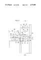
- FIG. 2 is a vertical sectional view taken along the line 2--2 of FIG. 3, which illustrates one practical embodiment of the apparatus shown in FIG. 1;
- FIG. 3 is a front view of the embodiment shown in FIG. 2 as viewed from the left-hand side thereof;
- FIG. 4 is a horizontal sectional view taken along the line 4--4 of FIG. 3;
- FIG. 5 is a fragmentary vertical sectional view illustrating a signature stream interruption correcting mechanism provided in a signature introducing section which is in an operative state in contrast to the corresponding part of the arrangement shown in FIG. 2;
- FIGS. 6 to 10 are fragmentary vertical sectional views successively illustrating the stacking operation according to the present invention.
- FIG. 11 is a fragmentary plan view illustrating a pressing and banding mechanism provided in the tying section which is in an operative state in contrast to the corresponding part of the arrangement shown in FIG. 4;
- FIGS. 12 to 14 are enlarged perspective views respectively illustrating various embodiments of signature pressing mechanisms 43 and 44 provided in the signature introducing section, in which FIGS. 12, 13 and 14 show first, second and third embodiments, respectively;
- FIG. 15 is an enlarged side view illustrating a first embodiment of the signature stacking mechanism according to the present invention.
- FIG. 16 is an enlarged side view illustrating a second embodiment of the signature stacking mechanism
- FIG. 17 is an enlarged side view illustrating a first embodiment of an auxiliary mechanism for stacking signatures according to the present invention.
- FIG. 18 is a vertical sectional front view taken along the line 18--18 of FIG. 17;
- FIG. 19 is a fragmentary perspective view of the arrangement shown in FIG. 17 as viewed from the obliquely forward side thereof;
- FIG. 20 is a perspective view illustrating a modification of the arrangement shown in FIG. 19;
- FIG. 21 is a perspective view illustrating a third modification of the arrangement shown in FIG. 19;
- FIG. 22 is a perspective view illustrating a fourth modification of the arrangement shown in FIG. 19;
- FIG. 23 is a plan view of a first embodiment of a means for attaching a panel to the front end of a stack of signatures according to the present invention.
- FIG. 24 is a side view of the embodiment shown in FIG. 23;
- FIG. 25 is a plan view illustrating a second embodiment of the means for attaching a panel to the front end of a stack of signatures
- FIG. 26 is a plan view illustrating a forwardly turned-up phenomenon which occurs in the case where no panel is attached to the front end of a stack of signatures;
- FIG. 27 is a side view illustrating a first embodiment of a means for attaching a panel to the rear end of a stack of signatures according to the present invention in relation to the general arrangement of the signature stacking mechanism;
- FIG. 28 is a perspective view of an essential part of the embodiment shown in FIG. 27;
- FIGS. 29 to 34 respectively illustrating various embodiments of the means for attaching a panel to the rear end of a stack of signatures.
- FIG. 35 is a vertical sectional view taken along the line 35--35 of FIG. 28.
- a guide plate 14 for stacking signatures which is used in the present invention is defined by a slide-like slope having a predetermined angle of inclination throughout it.
- a transport means is provided at the same level as that of the surface of the slope, the transport means including a combination of a first support member 16 and a second support member 17 which are adapted to support the foremost surface of a stack of signatures and move along a slit longitudinally provided in the guide plate 14, the support members 16 and 17 being further adapted to emerge and withdraw from the surface of the guide plate 14.
- Signatures are transported onto the uppermost portion of the guide plate 14 from the upper side of the latter, for example, in a direction perpendicular to the surface of the guide plate 14.
- the stream 20 of signatures is on the first lower conveyor 21, the bulge at the folded side of each signature is eliminated and respective lateral edges of the signatures are aligned so as to be in exact register with each other. Any discontinuance of the stream 20 is corrected by the action of the second lower conveyor 22.
- the number of signatures which constitute a stream 20 is counted at the third lower conveyor 33.
- the stream 20 of signatures is divided into discrete signatures at the fourth lower conveyor 24, and the signatures in the discrete state are then introduced onto the guide plate 14 in a direction approximately perpendicular to the plane of the guide plate 14.
- a pair of upper and lower pressure rollers 43 and 44 are disposed in opposing relation to each other across the first lower conveyor 21 so that the stream 20 of signatures travels through the area between the rollers 43 and 44.
- the force required for the rollers 43 and 44 to press the signatures may be obtained from, for example, a spring (not shown) in the form of resilient force.
- a pair of oscillating side plates 26 and 27 are provided on the upper side and at two lateral edges, respectively, of the lower conveyor 21 as shown in FIG. 3.
- the pair of side plates (joggers) 26 and 27 are adapted to jog both lateral edges of the stream 20 of signatures in order to correct any misalignment of the lateral edges of the signatures.
- the second lower conveyor 22 has an extremely short length, and a downstream pulley 28 has a smaller diameter than that of an upstream pulley 29.
- the relatively small pulley 28 is adapted to project obliquely upward toward the downstream side along an arcuate path whose center of a curvature is located on the axis of a shaft for the upstream pulley 29 (see FIG. 5).
- a light projector 31 and a light receiver 32 are provided immediately downstream of the small pulley 28 in such a manner that a beam 30 of light crosses vertically the stream 20 of signatures. The arrangement is such that, when the stream 20 of signatures becomes discontinuous, the light beam 30 is received by the light receiver 32 and the latter generates a signal.
- An upper conveyor 33 is provided above the third lower conveyor 23 to press, particularly by the action of a presser pulley 34, the stream 20 of signatures so that they are prevented from rising.
- the stream 20 of signatures thus pressed satisfactorily is irradiated with a laser beam 36 from a laser oscillator 35 disposed above and downstream of the irradiated position so that the laser beam 36 is obliquely incident on the upper side of the stream 20, and the light reflected therefrom is received by a light receiver 37. Since the laser beam 36 is interrupted every time the leading end of each signature passes this detecting position, the number of passing signatures can be detected by counting the number of times of interruption of the laser beam 36.
- the fourth lower conveyor 24 runs horizontally, whereas the fifth lower conveyor 25 is slanted to run obliquely downward in order to regulate the postures of signatures so that they are introduced to the guide plate 14 in a direction perpendicular to the plane of the guide plate 14.
- the bend of the transport path between the horizontal section and the obliquely downward section is formed at the position of an intermediary pulley 38 which intermediates between the fourth and fifth conveyors. At this bend, the leading end edge of each signature is separated from the upper surface of the preceding signature to produce a gap therebetween.
- the stream 20 of signatures is divided by making good use of the phenomenon that the leading end of each signature is separated from the preceding signature at the moment said leading end passes the bend of transport path.
- the dividing mechanism is, of course, activated in close cooperation with the above-described counting mechanism.
- the dividing mechanism consists of a dividing plate 39 provided immediately downstream of the intermediary pulley 38 at a position which faces the pulley 38 obliquely downward, an air cylinder 40 for activating the dividing plate 39, an accumulating plate 41 provided above the intermediary pulley 38, and a lifting member 42 provided at a position which is immediately upstream of the intermediary pulley 38 and which is immediately below the conveyor 24.
- the air cylinder 40 When a signal which indicates the completion of counting of a predetermined number of signatures is output from the counting mechanism, the air cylinder 40 is activated to lower the dividing plate 39 so as to intercept the succeeding stream 20 of signatures by the accumulating plate 41 and, at the same time, the lifting member 42 is projected above the conveyor 24 to raise the succeeding stream 20 of signatures to thereby remove the load from the rearmost signatures of the preceding stream 20. In consequence, said rearmost signatures are released and separated from the foremost signatures of the succeeding stream 20, thus achieving division of the stream 20 of signatures. Thereafter, each mechanism is returned to its initial position, and the succeeding stream 20 of signatures is transported on the conveyor 25.
- the final lower conveyor 25 cooperates with an upper conveyor 45 disposed above it to reliably lead the signatures 20 to the guide plate 14 in a dierection perpendicular to the plane of the guide plate 14.
- the upper conveyor 45 is provided so as to extend below the plane of the guide plate 14 in order to enable the folded portion of each signature 20 to be reliably fed to the surface of the guide plate 14.
- the upper conveyor 45 further serves to prevent the signatures 20 from rising upward during transportation.
- the guide plate 14 for stacking signatures is defined by a slope having a predetermined angle of inclination as has already been described.
- Stacking of signatures is accomplished by the cooperation of the guide plate 14 and the first and second support members 16, 17 which share with each other in retaining the foremost end of a stack of signatures in such a manner that the first support member 16 retains said foremost end during a first half of each stacking operation and the second support member 17 retains said foremost end during a second half of the stacking operation, together with a third support member 18 which retains the rearmost end of the stack of signatures from beginning to end of each stacking operation.
- the first support member 16 plunges into the guide plate 14 from the outer side thereof along the prolongation line of the lower conveyor 25 to await oncoming signatures before the foremost portion of the divided stream of signatures is introduced to the upper part of the guide plate 14.
- the first support member 16 is gradually lowered (see FIG. 9) in accordance with the loading speed. The gradual lowering of the first support member 16 continues until it reaches the stand-by position of the second support member 17 (see FIG. 10) where the first support member 16 is withdrawn to the outside of the guide plate 14 (see FIG. 7).
- the second support member 17 is allowed to stand by at a position adjacent to the first support member 16 in timed relation to the downward movement of the latter, as shown in FIGS. 10 and 6.
- the withdrawn first support member 16 is moved upward to the plunging position therefor to stand by thereat as shown in FIG. 7.
- the first support member 16 plunges into the upper part of the guide plate 14 to await the following stream 20 of signatures.
- the second support member 17 which has taken over the supporting of the foremost end of the stack of signatures from the first support member 16 advances to a signature stack unloading position on the guide plate 14 while retaining the foremost end of the stack of signatures (see FIGS. 8 and 9).
- the third support member 18 plunges into the guide plate 14 along the transport line of the upper conveyor 45 to stand by, and when the loading of signatures is temporarily stopped by the action of the dividing plate 39, that is, when signatures descending through the transport path (see FIG. 8) have already been received on the guide plate 14, the third support member 18 starts to lower and retains the rearmost end of the stack of signatures and then advances to the loading position on the guide plate 14 in cooperation with the second support member 17 to hold the stack (see FIG. 9).
- an oscillating plate 47 is provided at a position spaced apart from the guide plate 14 by a distance equal to the length of each signature, the plate 47 being adapted to pivot about the axis of a shaft 46 so as to jog the respective rear end edges of the signatures to thereby correct any irregularity in alignment of the growing stack of signatures.
- a panel stack support plate 48 for stacking a multiplicity of panels thereon is provided above the signature stack unloading position in such a manner that a panel 49 which is disposed at the leftward end of the plate 48 is located immediately above the rearmost end of the signature stack unloading position, the panels 49 being successively supplied from the one which is at the leftward end.
- panels 49 are supplied to both ends, respectively, of a stack of signatures, the panel supplying process carried out at the forward end of a stack of signature differs from that at the rearward end thereof.
- the second support member 17 is provided in advance with a notch 50 the upper side of which is open (see the two-dot chain line in FIG. 9).
- a notch 50 the upper side of which is open (see the two-dot chain line in FIG. 9).
- a claw 51 is first activated to catch the upper end surface of a panel 49, thus causing the panel 49 to be pressed downward and then held by a rotating rubber roller 52, and in this way, the panel 49 is inserted into the notch 50 by virtue of the rotation of the roller 52.
- the second support member 17 having the panel 49 inserted therein then returns to its stand-by position adjacent to the first support member 16 as shown in FIG. 6 to take over supporting of the foremost end of the stack of signatures from the first support member 16. Thereafter, as shown in FIG. 9, the second support member 17 advances to the forward end of the signature stack unloading position and withdraws to the lower side of the guide plate 14. At this time, the panel 49 alone is blocked by the guide plate 14 and thereby removed from the notch 50 and left on the guide plate 14, the outer side of the panel 49 being supported by a paper guide 53.
- an auxiliary plate 54 is lowered along the rear side of the support member 18 in response to the movement of the latter (see FIG. 9).
- the auxiliary plate 54 is able to pivot about a support shaft 75 so that the plate 54 is normally positioned so as to extend horizontally as shown in FIG. 10 to thereby open the path of the stack of signatures and, only when a panel 49 is supplied, the auxiliary plate 54 extends vertically.
- the panel 49 is inserted into the area between the third support member 18 and the auxiliary plate 54 by the action of the rubber roller 52. Upon completion of the insertion of the panel 49, the third support member 18 is withdrawn below the guide plate 14.
- the stack of signatures having the panels 49 respectively applied to both ends thereof is unloaded to one side of the guide plate 14 by the action of a pusher plate 55 as shown in FIGS. 3 and 4.
- the pusher plate 55 is rigidly secured to an endless chain 56 which is stretched between a pair of sprockets 57 and 58.
- the stack of signatures is transported by the operation of this set of transport means along paper guides 53, 59, 60 and 61 to reach a position immediately below a banding arch 62 having the same slope and the same height as the guide plate 14.
- the stack of signatures is pressed against the paper guides 61 by press plates 69 and 70 which are connected through brackets 67 and 68 to rods 65 and 66 of two cylinders 63 and 64, respectively (see FIGS. 4 and 11).
- the stack of signatures is held by a pair of bars 71 and 72 in order to prevent the signatures from being sprung up when they are pressed.
- the stack of signatures is tied with a band 73 which is led out of the arch 62, thus completing tying.
- the band 73 is supplied from a reel 74.
- signatures are stacked on the guide plate 14 having a curvature of 0 and a predetermined angle of inclination in such a manner that the folded side of each signature face downward, and this produces a unique load distribution in which the maximum load concentrates on the lower part of each signature to strongly press it in the direction of thickness thereof to thereby thin this portion and in which the magnitude of the pressing force gradually lowers toward the upper part of each signature.
- the apparatus according to the present invention is provided with flexibility which enables the apparatus to widely cope with variations in the difference in terms of the thickness of signatures between the upper and lower parts thereof.
- the present invention enables a considerably large number of signatures to be stacked at a time by the action of the first and second support members 16 and 17, and this permits the apparatus to operate at high speed.
- FIGS. 12 to 14 respectively show first to third embodiments of the signature pressing apparatus according to the present invention.
- a signature (not shown) is passed through a press area 78 defined between a pair of rotary systems 43 and 44 which are in endless contact with each other, the rotary systems 43 and 44 having a width longer than the fold line of the signature, whereby an acute folding angle is formed at the folded side of the signature and the thickness of the signature is reduced.
- the pair of rotary systems 43 and 44 may be defined by a pair of rollers as shown in FIGS. 12 and 13.
- the pair of rotary systems 43 and 44 may be defined by a combination of one rotary system which is constituted by, for example, the roller 43, and the other rotary system which is constituted by, for example, an endless belt 44a and an auxiliary plate 44b for pressing which is provided on the lower surface of the endless belt 44a.
- Pressure relief grooves 76 and 77 are circumferentially formed in the peripheral surface of at least one of the pair of rotary systems 43 and 44, for example, the roller 43. However, the grooves 76 and 77 may be formed on both the rotary systems 43 and 44 as shown in FIG. 12.
- the grooves 76 which are formed in the peripheral surface of the roller 43 need to correspond to saddle stitching positions, respectively, of a signature which is to be pressed by the roller 43.
- the width of the grooves 76 is preferably set so as to be equal to or longer than the width of saddle stitching, that is, the length of stitching by a stitching wire.
- the present invention is still effective even when the groove width is slightly shorter than the saddle stitching width.
- the number of grooves 76 (77) per roller be equal to the number of stitching wires which are driven along the fold line of a set of signatures.
- the present invention is still effective even when said number of grooves 76 (77) is greater or smaller than said number of stitching wires.
- two grooves 76 or 77 are provided per roller.
- the depth and configuration of the grooves 76 and 77 are not particularly limited, provided that the grooves which are actually formed provide effectiveness in preventing a folded portion of a signature which is to be stitched from becoming acute.
- the width of the pressure relief grooves 76 and 77 is made greater than an actual one with respect to the entire width of the rollers 43 and 44 due to restriction by the size of paper and for the purpose of facilitating illustration.
- the total length of stitching wires, that is, the grooves 76 or 77, with respect to the overall length of the folding line of a signature is considerably small, and therefore the provision of the grooves 76 or 77 causes substantially no reduction in the pressing effectiveness. Accordingly, it is possible to expect the same pressing effectiveness as that obtained conventionally by employing the rollers 43 and 44 according to the present invention.
- a stream 20 of signatures completed with printing and folding in which the signatures overlap one another at a predetermined pitch is transported between two endless conveyor belts 25 and 45 which travel adjacent to each other so that the signatures are downwardly loaded onto the guide plate 14 in a direction perpendicular to the plane of the latter.
- the lower end of the belt 45 extends to the lower side of the guide plate 14 to support the rear end of a stack 13 of signatures.
- the forward end of the stack 13 of signatures is supported by the first support member, that is, a front retainer 16.
- the overall length of the stack 13 is increased by an amount corresponding to the thickness of the newly loaded signature. Accordingly, in such case if the front retainer 16 advances a distance corresponding to the thickness of the signature, the stack 13 of signatures can grow smoothly without causing neighboring signatures to be tightly pressed against each other. To achieve this, if the squeezing pressure caused by the newly loaded signature is directly transmitted to the front retainer 16 so as to move the latter, it becomes impossible to satisfactorily move the front retainer 16 as the overall length of the stack 13 of signatures increases, as detailed above in the description of the prior art.
- both the conveyor belts 25 and 45 (see FIG. 15) or the latter 45 alone (see FIG. 16) is supported by an oscillating member which is able to pivot backward against the force from a spring 86, for example, a lever 88 which has a pivot point 87 at its upper end and a free end at its lower side, and for this purpose, the respective shafts of the pulleys 80, 81, 82, 83, 84 and 85 (see FIG. 15) or the respective shafts of the pulleys 83, 84 and 85 (see FIG. 16) are provided on the lever 88 so that said shafts project from the plane of the latter.
- a spring 86 for example, a lever 88 which has a pivot point 87 at its upper end and a free end at its lower side, and for this purpose, the respective shafts of the pulleys 80, 81, 82, 83, 84 and 85 (see FIG. 15) or the respective shafts of the pulleys 83, 84 and 85 (see
- the amount of mechanical backward angular displacement thus obtained is detected by a transducer, e.g., a differential transformer 89, which is linked to the free end of the lever 88, and immediately converted to an electrical amount which is then supplied to a drive means, e.g., a servomotor 90.
- a transducer e.g., a differential transformer 89
- a drive means e.g., a servomotor 90.
- the servomotor 90 is provided as a drive source for the front retainer 16; therefore, when supplied with the electrically converted value, the servomotor 90 immediately applies the corresponding mechancial forward displacement amount to the front retainer 16.
- the guide plate 14 may be disposed horizontally, but it is preferable that the guide plate 14 be inclined forward so as to assume a slide-like posture in order to enable the stack 13 of signatures to shift forward more easily.
- an endless conveyor 91 which is defined by, for example, a nylon chain, is provided along the plane of the guide plate 14 and run at all times independently of the movement of the front retainer 16, or this endless conveyor 91 is driven so as to intermittently advance in response to the advancement of the front retainer 16 by means of a signal delivered from the transducer 89.
- the former arrangement has the advantage that the operation becomes speedy, while the latter has the advantage that no scuff mark is left on the lower side of the stack 13 of signatures, and both of these arrangements are particularly effective when the thickness of the stack 13 of signatures increases.
- the transducer for the purpose described above, it is also possible to provide, for example, a potentiometer (not shown) at the pivot point 87 for the lever 88 and supply a value output from the potentiometer to the motor 90.
- a potentiometer (not shown) at the pivot point 87 for the lever 88 and supply a value output from the potentiometer to the motor 90.
- the mechanical backward displacement amount of a conveyor is taken out by means of an oscillating member having a relatively small mass, for example, the lever 88 or the horizontal slider (not shown), while the mechanical backward displacement amount thus taken out is converted to an electrical amount by means of a transducer, for example, the differential transformer 89 or the potentiometer (not shown), and the electrically converted amount is converted to a mechanical forward displacement amount so as to advance the front retainer 16 by a distance corresponding to this displacement amount. Accordingly, the response in a high-speed operation is ensured and quickened.
- the guide plate 14 is inclined forward so as to assume a slide-like posture and the conveyor 91 is additionally provided in order to promote the forward shift of the stack 13 of signatures, a new signature can readily be loaded and no pressure is shifted to the inside of the stack 13 of signatures. Accordingly, it becomes possible to stack signatures smoothly and regularly.
- the present invention enables the above-described arrangement to be accomplished simply by making use of the existing mechanism and remodeling only a small number of portions thereof without the need to employ a large-scale mechanism. It is, therefore, possible to produce the apparatus at relatively low costs, and failures are not readily generated. In addition, no substantial time and labor are needed to conduct maintenance, inspection and adjustment. Accordingly, the present invention provides a great practical value.
- a stream 20 of signatures completed with printing and folding in which the signatures overlap one another at a predetermined pitch is transported between two endless conveyor belts 25 and 45 which travel adjacent to each other.
- the rear side of the stream 20 of signatures is supported by a third conveyor belt 45a which is stretched between the pulley 83 and a pulley 83a disposed below it and travels endlessly counterclockwise. In this way, the stream 20 of signatures is downwardly loaded onto a plane 14 in a direction perpendicular to the latter.
- signatures may be upwardly loaded onto the plane 14 in a direction perpendicular to the latter. In such case, there is a need to provide a stopper for defining the upper extremity of travel of loaded signatures.
- the plane 14 is denoted by a guide plate, it is not necessarily needed to be a visible plate surface and may be defined by two parallel chain conveyors; in such case also, signatures which are loaded thereonto can be stacked horizontally.
- the reference numeral 13 denotes a stack of signatures which are stacked horizontally on the plane 14 in such a manner that the respective lower ends of the signatures are in exact register with each other.
- An endless conveyor for shifting the stack 13 of signatures forwardly for example, a chain 91, is provided in the longitudinally central portion of the guide plate 14, so that the central portion of the lower end of each signature on the guide plate 14 is in contact with the chain 91 and the signature is thereby advanced by the action of the chain 91.
- This forward movement of signatures is uniformly caused throughout the stack 13 even at the rearmost signature of the the stack 13, that is, a signature 20a which has just been loaded, provided that the central portion of the lower end of the signature is in contact with the chain 91.
- the chain 91 cannot be provided at a portion of the lower end of a signature other than the central portion thereof, particularly a portion closer to a corner thereof, since there are variations in width of signatures.
- a feed member 92 is provided in such a manner that it is able to come into contact with one side edge portion of the signature 20a which has just been loaded and which defines the rear end of the stack 13 of signatures, and a means for driving the feed member 92 in such a manner that the feed member 92 is moved while maintaining the contact with the side edge portion of the signature 20a in a direction in which the stack 13 of signatures is advanced, thus enabling the side edge portion of the signature 20a to be advanced simultaneously with the advancement of the central portion of the lower end thereof.
- the feed member 92 is adapted to move forward the side edge portion of a signature 20a which has just been loaded and which defines the rear end of the stack 13 of signatures, but the feed member 92 may also be adapted to act so as to move forward the respective side edge portions of several signatures which have already been stacked ahead of the signature 20a.
- the feed member 92 may include a straight toothed pinion (see FIGS. 17 to 19) rotated through a shaft, a toothed endless belt 92a (see FIG. 20) which travels between two shafts, a worm-like screw 92b (see FIG. 21) rotated through a horizontal shaft, and a rack-like toothed plate 92c which repeats advancement, separation, retraction and contact.
- a material for these means serving as the feed member 92 it is preferable to employ a non-rigid material, e.g., nylon or rubber, which will not damage the side edges of signatures.
- a hair- or brush-like material or a file-like friction material may be attached to the surface of the area of the feed member 92 which comes into contact with signatures; in such case also, the same effectiveness can be achieved.
- the feed member 92 is driven by rotating the shaft 93 supporting it by a drive system (not shown), and the rotational speed of the feed member 92 is preferably changed in accordance with the rate at which signatures are loaded.
- the size of signatures which are stacked on the plane 14 is not the same at all times and there are cases where the size of signatures which are loaded changes, for example, from the size A4 to the size B4 and vice versa. In such cases, there is inevitably a change in the relative position of the side edge portions of signatures due to the difference in terms of the width of signatures. Even when there is no change in the size of signatures, there are cases where there is a considerable change in the quality of paper constituting signatures or in the number of pages defined by each signature. In such cases, it may be preferable to change and adjust the level of pressure with which the feed member 92 comes into contact with side edge portions of signatures.
- FIGS. 17 and 18 There may be a variety of means for adjustably moving the feed member 92.
- One example of such means is shown in FIGS. 17 and 18, in which are provided a bracket 94 for rotatably supporting the shaft 93 and a slider 95 which is integral with the bracket 94, the slider 95 being movably attached to a guide 97 which is integral with a support plate 96.
- a bearing 98 is provided so as to project from the outer side of the upper surface of the plate 96, and the neck portion of an adjusting screw 99 is rotatably supported by the bearing 98, while the distal end portion of the adjusting screw 99 is engaged with an internally threaded bore 100 which is provided in the bracket 94.
- the screw 99 is rotated to move the bracket 94 which is in engagement with the screw 99 through the bore 100, and the bracket 94 is thus moved in a direction of movement of the slider 95 mounted on the guide 97. Accordingly, the position of the feed member 92 can be adjusted in the direction of the width of the signature 20a by operating the handle 101.
- a lock mechanism (not shown) is used.
- the positional adjustment may be effected not only by manually operating the handle 101 but also by activating a motor (not shown), and both may be used in combination.
- the apparatus of the present invention may be omitted or rested for such side edge portions of signatures.
- the side edge portion of the signature 20a which has just been loaded and which defines the rear end of the stack 13 of signatures can be advanced by the action of the feed member 92, 92a, 92b, 92c or the like simultaneously with the advancement of the central portion of the signature 20a and in the same way as the latter. Accordingly, room for receiving a following signature is provided at the rear end of the stack 13 of signatures, so that the following signature can be smoothly and reliably inserted until it reaches the plane 14 without any fear of the signature being interfered or blocked halfway the loading path.
- the contact position or the level of contact pressure can speedily and readily be adjusted by a simple and inexpensive mechanism.
- any misalignment of lateral edges of loaded signatures can quickly be corrected by the feed operation of the feed member so that the signatures are positioned in an optimal state, thus enabling formation of a satisfactory stack of signatures in which the side edges of the signatures are in exact register with each other.
- FIGS. 23 to 25 show in combination a first embodiment wherein two actuators X and Y are disposed in relation to each other on orthognal coordinate axes, respectively, and FIG. 25 shows a second embodiment wherein a single common actuator W is adapted to sectorially act on a polar coordinate system.
- the first embodiment will first be explained below.
- a stream 20 of signatures completed with printing and folding in which the signatures overlap one another at a predetermined pitch is transported between two endless conveyor belts 25 and 45 which travel adjacent to each other so that the signatures are vertically loaded onto the guide plate 14 successively and stacked horizontally thereon to gradually form a stack 13 of signatures.
- the guide plate 14 has a gap 102 provided in its central portion so as to extend in the longitudinal direction.
- a conveyor 91 for transporting a stack 13 of signatures is disposed to run in the center of the gap 102, and panel transport members (serving as the above-described second support member) defined by two upstanding rods 17 are disposed in such a manner that the rods 17 extend upward through two left and right gap areas 102, respectively, which are defined by the conveyor 91.
- a panel 49 is transported by the transport members 17 to a predetermined position halfway the guide path on the guide plate 14 and stopped thereat to await the arrival of the front end 13a of the stack 13 of signatures.
- the stack 13 of signatures formed on the guide plate 14 is supported at the central portion of its front end 13a by temporarily retaining members (serving as the above-described first support member) which are defined by two upstanding rods 16,
- the rods 16 also upwardly extend through the gap areas 102 as shown in FIG. 24 to temporarily retain the central portion of the front end 13a of the stack 13 of signatures and, while doing so, they move on the guide plate 14 leftward as viewed in the figures.
- the upstanding rods 16 When reaching the position where the panel 49 stands by, the upstanding rods 16 lower below the guide plate 14 and move, in this lowered state, rightward as viewed in the figures to their initial positions where they project above the guide plate 14 again when a subsequent stack 13 of signatures is to start to grow so as to temporarily retain the central portion of the front end 13a of the stack 13 of signatures.
- the transport members 17 for supporting the panel 49 move leftward as viewed in the figures.
- the apparatus according to the present invention is provided with support members 103 which come into contact with two lateral edge portions, respectively, of the front end 13a of the stack 13 of signatures.
- the support members 103 may be of roller type, plate type, brush type or air nozzle type.
- Example of a material for the support members 103 include a synthetic resin, a metal, wood, asbestos and sisal.
- the support membes 103 may be either rigid, elastic or flexible.
- a pair of right and left support members 103, that is, two support members 103, are generally provided as illustrated. However, since the degree to which an edge portion of a signature is turned up is lower at the folded side than that at the leaf side, the support member 103 for the folded side may be omitted.
- Second guide plates 104 are provided above the guide plate 14 so as to extend in the longitudinal direction of the latter, the guide plates 104 being provided with respective slots 105 through which the upper end portions of the support members 103 extend.
- Air cylinders 106 (corresponding to the actuators X) are provided at the front ends of the second guide plates 104, respectively, and the distal ends of rods 107 of the air cylinders 106 are rigidly secured to the upper ends of the support members 103, respectively.
- the pressure control may be such that a pressure reducing valve (not shown) is provided in an air circuit for supplying air to the air cylinders 106 in order to enable adjustment of the level of pressure, thereby allowing prevention of warpage of the front end 13a of the stack 13 of signatures and also permitting the support members 103 to move backward while following the advancement of the stack 13 of signatures.
- the support members 103 may be retracted either sideward, upward or obliquely upward. In the illustrated embodiment they are retracted sideward.
- a rod 109 is projected outward from the intermediate portion of the corresponding second guide member 104 and the rod 109 is moved outward by the operation of a solenoid (corresponding to the actuator Y).
- the solenoid 108 is excited, for example, in response to a excitation command which is issued by detecting with a sensor (not shown) the fact that the support member 103 which is moved backward comes into contact with the panel 49.
- the support members 103 When the support members 103 are retracted from the passage space for the stack 13 of signatures by the operation of the solenoids 108, the load of the signatures is removed and therefore the support members 103 are automatically returned to the right-hand ends of the respective slots 105 by the forces from the air cylinders 106 as described above and await the passage of the stack 13 of signatures thereat.
- the solenoids 108 When the passage of the stack 13 of signatures is detected by the sensor (not shown), the solenoids 108 are de-energized in response to a detection signal from the sensor, and the support members 103 are advanced into the space for stacking signatures.
- temporarily retaining members 16 are also adapted to lower below the guide plate 14 after coming into contact with the panel 49 and rise above the guide plate 14 at the position where the support members 103 are advanced, as shown in FIG. 24.
- an externally threaded rod 111 is mounted on a machine frame 110 in such a manner that the rod 111 is axially movable and rotatable back and forth, and an internally threaded bore is provided in a slide block 112 which is integral with the corresponding solenoid 108, the rod 111 being engaged with the bore.
- guide shafts 113 are provided so as to project from the machine frame 110 in order to prevent the rotation of the slide block 112 and allow it to move only in the axial direction, and the slider block 112 is thus guided along the shafts 113.
- the handle 114 may readily be arranged so as to be operated manually, automatically or selectively by a manual or automatic operation, and a means for locking the adjusted contact position can readily be provided if desired although illustration thereof is omitted.
- Each support member 103 is attached to the free end of an oscillating lever 115 the proximal end of which is pivotally supported through a shaft 116 by one end of the slider block 112.
- the free end portion of an arm 117 which probjects from the shaft 116 is linked to the distal end portion of a rod 119, and this rod 119 is actuated by an air cylinder 118 (corresponding to the actuator W).
- the support member 103 is sectorially moved about the shaft 116 by the action of a single common actuator 118. Therefore, although the contact position of the support member 103 is displaced slightly as the front end 13a of the stack 13 of signatures moves, it is possible to satisfactorily prevent the front end 13a of the stack 13 from being turned up, and in addition, when coming into contact with the panel 49, the support member 103 is automatically retracted to the outside of the passage of the stack 13 of signatures. On the other hand, since signatures are continued to be stacked thereafter, the support member 103 is drawn leftward as viewed in the figure by the action of the air cylinder 118 so that the support member 103 will not obstruct stacking of signatures.
- the support member 103 is sufficiently retracted outward of the signature stacking space and, in this position, the support member 103 awaits the passage of the stack 13 of signatures.
- the rod 119 is projected rightward as viewed in the figure by the action of the air cylinder 118 to thereby return the support member 103 so as to come into contact with the front end 13a of the stack 13 of signatures.
- the position of the support member 103 can be altered for adjustment by moving the slide block 112 in order to cope with a change in the width of signatures.
- the present invention Since the contact positions of the support members 103 are made adjustable in correspondence with the width of signatures to be stacked, the present invention has the general-purpose property which enables it to be used in any kind of signature stacking apparatus and therefore provides a considerably high practical value.
- each of the signatures which have been completed with printing and folding is loaded onto the uppermost portion of a slide-like guide plate 14 from the upper side thereof.
- the foremost portion of the stack 13 of signatures is supported by a first support member 16 from the signature loading position A to the stand-by position for a second support member 17 and then supported by the second support member 17 from the stand-by position B to the unloading position (shown by the solid line in FIG. 27) for the stack 13 of signatures.
- the rear end 13b of the stack 13 which is the subject of the present invention, is pushed by a third support member 18 throughout the signature stacking space, that is, from the uppermost position A of the guide plate 14 to the lowermost end of the unloading position.
- the guide plate 14 is, as shown in FIG. 28, provided with two parallel slits 101 which extend longitudinally of the guide plate 14, and each of the support members extends upwardly through the slits 101 so as to project above the guide plate 14. Accordingly, the portion of each support member which projects above the guide plate 14 is defined by substantially two bar members.
- the bar portion of the second support member 17 which projects above the guide plate 14 is formed with a pair of front and rear prongs as shown in FIG. 27, so that a panel 49 can be supplied into the gap or slot defined between the two prongs at a position halfway the return path section of the moving path for the second support member 17 shown by the one-dot chain line arrows, that is, at the position C where the second support member 17 in a non-loaded state projects above the guide plate 14.
- the panel 49 is attached to the front end of the stack 13 of the signatures from the beginning, and when the second support member 17 is retracted to the lower side of the guide plate 14 at the final position of the stack supporting section, the panel 49 is left alone on the guide plate 14 and immediately supported by a paper guide 134 and, in this way, the panel 49 can readily be attached to the front end of the stack 13.
- a panel receiving intermediary box 120 such as that shown in each of the embodiments shown in FIGS. 30 to 35 is employed to attach a panel 49 to the rear end 13b of the stack 13 of signatures.
- the box 120 consists of a pair of plates 121 and 122 and a spacer 123 which interconnects these plates at one side edge of each of them.
- a panel 49 is received in the space defined between the pair of plates 121 and 122 retained by the spacer 123.
- the spacer 123 is provided at the rearward edge of the combination of the plates 121 and 122 in all the embodiments except for that shown in FIG. 30 in which the spacer 123 is provided at the forward edge.
- a panel insertion port 124 is opened along the upper edge of the box 120, and a panel discharge port 125 is provided at the forward edge in all the embodiments except for that shown in FIG. 30 in which the port 125 is provided at the rearward edge.
- Linear notches 126 for raking out a panel 49 are opened to the discharge port 125. Accordingly, in all the embodiments except for that shown in FIG. 30, a panel 49 is inserted into the box 120 from the upper side thereof and is discharged to the front side, whereas, in the embodiment shown in FIG. 30, a panel 49 is inserted into the box 120 from the upper side thereof and discharged to the rear side.
- the notches 126 are generally provided in the forward plate 121 but may be provided in both the plates 121 and 122 as shown in FIGS. 34 and 35. Further, the notches 126 may be provided in the plate so as to extend from the intermediate portion thereof as in the cases of the embodiments shown in FIGS. 29, 30 and 33 or may be provided so as to reach the spacer 123 as in the cases of the embodiments shown in FIGS. 31, 32 and 34. In addition, the notches 126 may be provided so as to extend along the upper and lower side edges, respectively, of the forward plate 121 as shown in FIG. 32. It should be noted that, when both the plates 121 and 122 are divided into three sections, these three sections are supported by a connecting member 127 as shown in FIG. 34.
- the box 120 having the above-described arrangement is attached to the rear end 13b of a stack 13 of signatures in a direction in which the former faces the latter by a means described below.
- a pivot shaft 128 is disposed at a position above the level at which the stack 13 of signatures passes on the guide plate 14, and an arm 129 is projected from the shaft 128.
- the rear side of the box 120 is secured through a spacing adjusting member 130 to the free end portion of the arm 129.
- the box 120 is able to oscillate between two positions, that is, an inoperative position (see the two-dot chain line position) which is outside the passage of the stack 13 of signatures and an operative position (see the solid line position) at which the box 120 comes into contact with the rear end 13b of the stack 13.
- a claw 131 is first activated to engage and push downward the upper end face of a panel 49.
- the panel 49 is thus inserted into the space in the box 120 while being guided by a pair of rubber rollers.
- a push member 132 is provided in order to move the whole of the stack 13 of signatures at a stroke in the direction of width of the signatures, and, as shown in FIG. 35, projections 133 for raking out a panel 49 are provided at the end of the push member 132, the projections 133 being disposed so as to extend into the innermost portions of the linear notches 126 in advance.
- the projections 133 which are integral therewith are also moved along the linear notches 126. Accordingly, the panel 49 within the box 120 is raked out from the discharge port 122 of the box 120 at the same time as the stack 13 of signatures is moved, resulting in the box 120 being left alone.
- the panel 49 is attached to the rear end 13b of the stack 13 of signatures.
- the push member 132 is moved from the forward end toward the rear end thereof in this embodiment.
- the third support member 18 is retracted to the lower side of the guide plate 14 before the push member 132 starts to move so that the support member 18 will not interfere with the advancement of the push member 132.
- the panel receiving intermediary box 120 is attached to the rear end 13b in a direction in which the former faces the latter, that is, in a direction in which the rearwardly bulging portion of the rear end 13b is pushed back by the box 120. It is therefore possible to eliminate the conventional problem that the rear end 13b of the stack 13 may be damaged.
- the present invention makes use of the transportation of the stack 13 of signatures in the widthwise direction as a means for directly attaching a panel 49 inserted into the box 120 to the rear end 13b of the stack 13 in such a manner that the panel 49 within the box 120 is also moved in synchronism with the widthwise movement of the stack 13 so that the box 120 is left alone in a direction parallel to the plane of the rear end 13b of the stack 13. Accordingly, it becomes possible to attach the panel 49 to the rear end 13b smoothly, simply, inexpensively and easily.
- the present invention enables the panel 49 to be reliably attached to the rear end 13b of the stack 13 at a normal position, there is no fear of the signatures being disordered when being bound, so that the operation carried out in a subsequent bookbinding step can be effected without any hitch or delay. Accordingly, the present invention is considerably effective in saving resources and reducing labor.
Abstract
Description
Claims (22)
Priority Applications (1)
| Application Number | Priority Date | Filing Date | Title |
|---|---|---|---|
| US07/018,341 US4772003A (en) | 1987-02-24 | 1987-02-24 | Apparatus for stacking signatures or the like |
Applications Claiming Priority (1)
| Application Number | Priority Date | Filing Date | Title |
|---|---|---|---|
| US07/018,341 US4772003A (en) | 1987-02-24 | 1987-02-24 | Apparatus for stacking signatures or the like |
Publications (1)
| Publication Number | Publication Date |
|---|---|
| US4772003A true US4772003A (en) | 1988-09-20 |
Family
ID=21787432
Family Applications (1)
| Application Number | Title | Priority Date | Filing Date |
|---|---|---|---|
| US07/018,341 Expired - Fee Related US4772003A (en) | 1987-02-24 | 1987-02-24 | Apparatus for stacking signatures or the like |
Country Status (1)
| Country | Link |
|---|---|
| US (1) | US4772003A (en) |
Cited By (34)
| Publication number | Priority date | Publication date | Assignee | Title |
|---|---|---|---|---|
| EP0339002A2 (en) * | 1988-04-18 | 1989-10-25 | O.M.G. di GIORGIO PESSINA E ALDO PEROBELLI S.n.c. | Continuous signature stacker machine provided with a special device for transversely ejecting the assembled package |
| US5009408A (en) * | 1989-03-16 | 1991-04-23 | Pulskamp Nicholas R | Continuous feed board inserter |
| US5014974A (en) * | 1990-01-16 | 1991-05-14 | Numerical Concepts, Inc. | In-line, continuous paper batching system |
| US5097959A (en) * | 1990-03-27 | 1992-03-24 | Westinghouse Electric Corp. | Multiple pass document sorting machine utilizing automatic sweeping and multiple recirculation trays |
| US5097960A (en) * | 1990-03-23 | 1992-03-24 | Westinghouse Electric Corp. | Multiple pass document sorting machine utilizing automatic sweeping |
| US5112042A (en) * | 1990-03-30 | 1992-05-12 | Westinghouse Electric Corp. | Document transfer device for multiple pass document sorting machine |
| US5114129A (en) * | 1990-12-14 | 1992-05-19 | R. R. Donnelley & Sons Company | Signature feeding apparatus |
| US5190281A (en) * | 1991-06-21 | 1993-03-02 | John Cardenas | Vertical signature stacking system having a non-contact sensor to control stack formation |
| US5244201A (en) * | 1991-06-20 | 1993-09-14 | Stacker Machine Co. | Signature stream interrupt apparatus and method |
| US5347790A (en) * | 1992-12-01 | 1994-09-20 | Electrocom Gard, Ltd. | Automatic traying and automatic sweeping device for letter mail |
| US5358232A (en) * | 1992-01-30 | 1994-10-25 | Bielomatik Leuze Gmbh + Co. | Method and device for producing defined stacks of folded or unfolded sheets |
| US5393196A (en) * | 1991-05-28 | 1995-02-28 | Winkler & Duennebier Maschinenfabrik Und Eisengiesserei Kg | Method and apparatus for stacking of envelopes or the like |
| US5441382A (en) * | 1993-01-29 | 1995-08-15 | Fleetwood Systems, Inc. | Infeed apparatus for article handling system |
| US5460479A (en) * | 1990-04-19 | 1995-10-24 | Neumann; Irving H. | Signature stacking machine |
| US5540422A (en) * | 1994-10-24 | 1996-07-30 | Baldwin Technology Corporation | Stacker-bundler transfer apparatus |
| EP0741101A2 (en) * | 1995-05-05 | 1996-11-06 | CIVIEMME S.r.l. | Method for separating a stack of signatures in a stacker and stacker for performing this method |
| EP0741099A2 (en) * | 1995-05-05 | 1996-11-06 | CIVIEMME S.r.l. | Horizontal stacker for signatures with cover feeder |
| FR2741055A1 (en) * | 1995-11-13 | 1997-05-16 | Realisations Etudes Et Commerc | DEVICE FOR REGULATING THE STACKING PRESSURE FOR A HORIZONTAL STACKING DEVICE OF NOTEBOOKS |
| US5758872A (en) * | 1996-10-23 | 1998-06-02 | Graphic Management Associates, Inc. | Bundling and strapping devices and methods |
| EP0847949A1 (en) * | 1993-05-07 | 1998-06-17 | Grapha-Holding Ag | Device for forming a stack of printed sheets, where these are piled on the edge |
| US5807064A (en) * | 1995-10-05 | 1998-09-15 | Baldwin Technology Corporation | Apparatus for continuously varying the position of an article carrying platform |
| FR2777876A1 (en) * | 1998-04-24 | 1999-10-29 | Realisations Etudes Et Commerc | Automatic stacker for books |
| US6003860A (en) * | 1997-03-18 | 1999-12-21 | Grapha-Holding Ag | Apparatus for forming partial stacks from printed sheets standing one behind the other |
| US6176483B1 (en) | 1997-03-12 | 2001-01-23 | Bell & Howell Mail And Messaging Technologies Company | High speed document separator and sequencing apparatus |
| EP1245518A2 (en) * | 2001-03-28 | 2002-10-02 | Gämmerler AG | Pile former |
| US20030082045A1 (en) * | 2001-10-22 | 2003-05-01 | Giuliano Cerutti | Machine and method for grouping products in stacks having a pre-set length |
| EP1350750A1 (en) * | 2002-04-03 | 2003-10-08 | Ferag AG | Method and device for forming piles of continuously delivered, flat ojects |
| EP1405809A1 (en) * | 2002-10-02 | 2004-04-07 | Müller Martini Holding AG | Device for forming parcels of stacked products |
| US20040245716A1 (en) * | 2003-05-21 | 2004-12-09 | Bates Jerry L. | Vertical pocket feeder |
| US20050206063A1 (en) * | 2002-07-19 | 2005-09-22 | Reinhard Gosslinghoff | Method and device for forming horizontal stacks of printed products and securing said stacks with straps |
| US20050285332A1 (en) * | 2004-06-23 | 2005-12-29 | Jean-Pierre Bodereau | Device for separation of folders in a layer of folders |
| US20110175279A1 (en) * | 2007-12-07 | 2011-07-21 | Robert Fokos | Under-shingled article handling and stacking system and method |
| US20150343827A1 (en) * | 2013-01-30 | 2015-12-03 | Mitsubishi Heavy Industries Printing & Packaging Machinery, Ltd. | Printing device, bookbinding device, and printing/bookbinding system |
| EP3590851B1 (en) * | 2018-07-02 | 2022-11-02 | H+H GmbH & Co. KG | Method and device for stacking folded products |
Citations (14)
| Publication number | Priority date | Publication date | Assignee | Title |
|---|---|---|---|---|
| US2776831A (en) * | 1953-01-09 | 1957-01-08 | S & S Corrugated Paper Mach | Sheet inverting mechanism |
| US3194127A (en) * | 1962-01-18 | 1965-07-13 | Sunds Verkst Er Aktiebolag | Device for stacking carton blanks and the like |
| US3772972A (en) * | 1972-03-20 | 1973-11-20 | Taylor M L | Stacker |
| US3772971A (en) * | 1971-05-27 | 1973-11-20 | Taylor M L | Batch stacker |
| US3822793A (en) * | 1972-04-14 | 1974-07-09 | Stobb Dev Corp Inc | Apparatus for stacking flexible sheets |
| US3927777A (en) * | 1972-05-15 | 1975-12-23 | Pneumatic Scale Corp | Method of loading magazine with cartons |
| US3932982A (en) * | 1972-12-15 | 1976-01-20 | Jagenberg-Werke Aktiengesellschaft | Apparatus for placing folded boxes or the like in shipping cartons |
| US4058226A (en) * | 1976-01-19 | 1977-11-15 | Box Innards, Inc. | High speed automatic stacker for partitions and the like |
| US4172531A (en) * | 1975-12-29 | 1979-10-30 | Grapha-Holding Ag | Apparatus for transforming a stream of overlapping paper sheets into a staple of sheets |
| US4302198A (en) * | 1977-01-26 | 1981-11-24 | Kabushiki Kaisha Tokyo Kikai Seisakusho | Odd copies bundling system in connection with fixed copies auto-bundling process |
| JPS587586A (en) * | 1981-06-29 | 1983-01-17 | ウエスチングハウス・エレクトリツク・コ−ポレ−シヨン | Manifold for cooling material for fusion reactor |
| JPS59135192A (en) * | 1983-01-24 | 1984-08-03 | 株式会社 東京機械製作所 | Folded section stacker |
| US4541763A (en) * | 1983-07-28 | 1985-09-17 | Harris Graphics Corporation | Apparatus for forming a stack of signatures |
| US4725180A (en) * | 1986-02-17 | 1988-02-16 | Shin Osaka Zoki Co., Ltd. | Apparatus for handling signatures before binding |
-
1987
- 1987-02-24 US US07/018,341 patent/US4772003A/en not_active Expired - Fee Related
Patent Citations (14)
| Publication number | Priority date | Publication date | Assignee | Title |
|---|---|---|---|---|
| US2776831A (en) * | 1953-01-09 | 1957-01-08 | S & S Corrugated Paper Mach | Sheet inverting mechanism |
| US3194127A (en) * | 1962-01-18 | 1965-07-13 | Sunds Verkst Er Aktiebolag | Device for stacking carton blanks and the like |
| US3772971A (en) * | 1971-05-27 | 1973-11-20 | Taylor M L | Batch stacker |
| US3772972A (en) * | 1972-03-20 | 1973-11-20 | Taylor M L | Stacker |
| US3822793A (en) * | 1972-04-14 | 1974-07-09 | Stobb Dev Corp Inc | Apparatus for stacking flexible sheets |
| US3927777A (en) * | 1972-05-15 | 1975-12-23 | Pneumatic Scale Corp | Method of loading magazine with cartons |
| US3932982A (en) * | 1972-12-15 | 1976-01-20 | Jagenberg-Werke Aktiengesellschaft | Apparatus for placing folded boxes or the like in shipping cartons |
| US4172531A (en) * | 1975-12-29 | 1979-10-30 | Grapha-Holding Ag | Apparatus for transforming a stream of overlapping paper sheets into a staple of sheets |
| US4058226A (en) * | 1976-01-19 | 1977-11-15 | Box Innards, Inc. | High speed automatic stacker for partitions and the like |
| US4302198A (en) * | 1977-01-26 | 1981-11-24 | Kabushiki Kaisha Tokyo Kikai Seisakusho | Odd copies bundling system in connection with fixed copies auto-bundling process |
| JPS587586A (en) * | 1981-06-29 | 1983-01-17 | ウエスチングハウス・エレクトリツク・コ−ポレ−シヨン | Manifold for cooling material for fusion reactor |
| JPS59135192A (en) * | 1983-01-24 | 1984-08-03 | 株式会社 東京機械製作所 | Folded section stacker |
| US4541763A (en) * | 1983-07-28 | 1985-09-17 | Harris Graphics Corporation | Apparatus for forming a stack of signatures |
| US4725180A (en) * | 1986-02-17 | 1988-02-16 | Shin Osaka Zoki Co., Ltd. | Apparatus for handling signatures before binding |
Cited By (54)
| Publication number | Priority date | Publication date | Assignee | Title |
|---|---|---|---|---|
| EP0339002A3 (en) * | 1988-04-18 | 1991-01-30 | O.M.G. di GIORGIO PESSINA E ALDO PEROBELLI S.n.c. | Continuous signature stacker machine provided with a special device for transversely ejecting the assembled package |
| EP0339002A2 (en) * | 1988-04-18 | 1989-10-25 | O.M.G. di GIORGIO PESSINA E ALDO PEROBELLI S.n.c. | Continuous signature stacker machine provided with a special device for transversely ejecting the assembled package |
| US5009408A (en) * | 1989-03-16 | 1991-04-23 | Pulskamp Nicholas R | Continuous feed board inserter |
| US5014974A (en) * | 1990-01-16 | 1991-05-14 | Numerical Concepts, Inc. | In-line, continuous paper batching system |
| US5097960A (en) * | 1990-03-23 | 1992-03-24 | Westinghouse Electric Corp. | Multiple pass document sorting machine utilizing automatic sweeping |
| US5097959A (en) * | 1990-03-27 | 1992-03-24 | Westinghouse Electric Corp. | Multiple pass document sorting machine utilizing automatic sweeping and multiple recirculation trays |
| US5112042A (en) * | 1990-03-30 | 1992-05-12 | Westinghouse Electric Corp. | Document transfer device for multiple pass document sorting machine |
| US5460479A (en) * | 1990-04-19 | 1995-10-24 | Neumann; Irving H. | Signature stacking machine |
| US5114129A (en) * | 1990-12-14 | 1992-05-19 | R. R. Donnelley & Sons Company | Signature feeding apparatus |
| US5393196A (en) * | 1991-05-28 | 1995-02-28 | Winkler & Duennebier Maschinenfabrik Und Eisengiesserei Kg | Method and apparatus for stacking of envelopes or the like |
| US5244201A (en) * | 1991-06-20 | 1993-09-14 | Stacker Machine Co. | Signature stream interrupt apparatus and method |
| US5190281A (en) * | 1991-06-21 | 1993-03-02 | John Cardenas | Vertical signature stacking system having a non-contact sensor to control stack formation |
| US5358232A (en) * | 1992-01-30 | 1994-10-25 | Bielomatik Leuze Gmbh + Co. | Method and device for producing defined stacks of folded or unfolded sheets |
| US5347790A (en) * | 1992-12-01 | 1994-09-20 | Electrocom Gard, Ltd. | Automatic traying and automatic sweeping device for letter mail |
| US5441382A (en) * | 1993-01-29 | 1995-08-15 | Fleetwood Systems, Inc. | Infeed apparatus for article handling system |
| EP0847949A1 (en) * | 1993-05-07 | 1998-06-17 | Grapha-Holding Ag | Device for forming a stack of printed sheets, where these are piled on the edge |
| US5727674A (en) * | 1994-10-24 | 1998-03-17 | Baldwin Technology Corporation | Stacker-bundler transfer apparatus with powered roller table |
| US5540422A (en) * | 1994-10-24 | 1996-07-30 | Baldwin Technology Corporation | Stacker-bundler transfer apparatus |
| EP0741099A2 (en) * | 1995-05-05 | 1996-11-06 | CIVIEMME S.r.l. | Horizontal stacker for signatures with cover feeder |
| EP0741099A3 (en) * | 1995-05-05 | 1997-07-30 | Civiemme Srl | Horizontal stacker for signatures with cover feeder |
| EP0741101A3 (en) * | 1995-05-05 | 1997-07-30 | Civiemme Srl | Method for separating a stack of signatures in a stacker and stacker for performing this method |
| EP0741101A2 (en) * | 1995-05-05 | 1996-11-06 | CIVIEMME S.r.l. | Method for separating a stack of signatures in a stacker and stacker for performing this method |
| US5807064A (en) * | 1995-10-05 | 1998-09-15 | Baldwin Technology Corporation | Apparatus for continuously varying the position of an article carrying platform |
| WO1997018152A1 (en) * | 1995-11-13 | 1997-05-22 | Realisations, Etudes & Commercialisation De Matériel Pour L'industrie, Societe Anonyme | Stacking pressure control device for a horizontal book stacking device |
| FR2741055A1 (en) * | 1995-11-13 | 1997-05-16 | Realisations Etudes Et Commerc | DEVICE FOR REGULATING THE STACKING PRESSURE FOR A HORIZONTAL STACKING DEVICE OF NOTEBOOKS |
| US5758872A (en) * | 1996-10-23 | 1998-06-02 | Graphic Management Associates, Inc. | Bundling and strapping devices and methods |
| US6176483B1 (en) | 1997-03-12 | 2001-01-23 | Bell & Howell Mail And Messaging Technologies Company | High speed document separator and sequencing apparatus |
| US6003860A (en) * | 1997-03-18 | 1999-12-21 | Grapha-Holding Ag | Apparatus for forming partial stacks from printed sheets standing one behind the other |
| FR2777876A1 (en) * | 1998-04-24 | 1999-10-29 | Realisations Etudes Et Commerc | Automatic stacker for books |
| US6782678B1 (en) * | 1998-04-24 | 2004-08-31 | Realisations, Etudes & Co Commercialisation De Materiel Pour L'industrie, Recmi | Stacking device and printed sections in the form of cartridges |
| WO1999055611A1 (en) * | 1998-04-24 | 1999-11-04 | Realisations, Etudes & Commercialisation De Materiel Pour L'industrie, Recmi | Stacking device and printed sections in the form of cartridges |
| US6889973B2 (en) | 2001-03-28 | 2005-05-10 | Gammerler Ag | Vertical log stacker |
| EP1245518A2 (en) * | 2001-03-28 | 2002-10-02 | Gämmerler AG | Pile former |
| DE10115251A1 (en) * | 2001-03-28 | 2002-10-10 | Gaemmerler Ag | log stacker |
| EP1245518A3 (en) * | 2001-03-28 | 2004-01-02 | Gämmerler AG | Pile former |
| US20030082045A1 (en) * | 2001-10-22 | 2003-05-01 | Giuliano Cerutti | Machine and method for grouping products in stacks having a pre-set length |
| US6971839B2 (en) * | 2001-10-22 | 2005-12-06 | Sps Italiana Pack Systems Spa | Machine and method for grouping products in stacks having a pre-set length |
| EP1350750A1 (en) * | 2002-04-03 | 2003-10-08 | Ferag AG | Method and device for forming piles of continuously delivered, flat ojects |
| US20030234485A1 (en) * | 2002-04-03 | 2003-12-25 | Reinhard Gosslinghoff | Method and device for producing stacks from continuously supplied, flat articles |
| US6951333B2 (en) | 2002-04-03 | 2005-10-04 | Ferag Ag | Method and device for producing stacks from continuously supplied, flat articles |
| US20050206063A1 (en) * | 2002-07-19 | 2005-09-22 | Reinhard Gosslinghoff | Method and device for forming horizontal stacks of printed products and securing said stacks with straps |
| US7200976B2 (en) * | 2002-07-19 | 2007-04-10 | Ferag Ag | Method and device for forming horizontal stacks of printed products and securing said stacks with straps |
| US20040065214A1 (en) * | 2002-10-02 | 2004-04-08 | Muller Martini Holding Ag | Apparatus for producing stack bundles |
| EP1405809A1 (en) * | 2002-10-02 | 2004-04-07 | Müller Martini Holding AG | Device for forming parcels of stacked products |
| US7021035B2 (en) | 2002-10-02 | 2006-04-04 | Müller Martini Holding AG | Apparatus for producing stack bundles |
| US20040245716A1 (en) * | 2003-05-21 | 2004-12-09 | Bates Jerry L. | Vertical pocket feeder |
| US7011302B2 (en) * | 2003-05-21 | 2006-03-14 | Systems Technology, Inc. | Vertical pocket feeder |
| US7131645B2 (en) * | 2004-06-23 | 2006-11-07 | Recmi Industrie | Device for separation of folders in a layer of folders |
| US20050285332A1 (en) * | 2004-06-23 | 2005-12-29 | Jean-Pierre Bodereau | Device for separation of folders in a layer of folders |
| US20110175279A1 (en) * | 2007-12-07 | 2011-07-21 | Robert Fokos | Under-shingled article handling and stacking system and method |
| US8360413B2 (en) * | 2007-12-07 | 2013-01-29 | Robert Fokos | Under-shingled article handling and stacking system and method |
| US8622379B2 (en) | 2007-12-07 | 2014-01-07 | Robert Fokos | Under-shingled article handling and stacking system and method |
| US20150343827A1 (en) * | 2013-01-30 | 2015-12-03 | Mitsubishi Heavy Industries Printing & Packaging Machinery, Ltd. | Printing device, bookbinding device, and printing/bookbinding system |
| EP3590851B1 (en) * | 2018-07-02 | 2022-11-02 | H+H GmbH & Co. KG | Method and device for stacking folded products |
Similar Documents
| Publication | Publication Date | Title |
|---|---|---|
| US4772003A (en) | Apparatus for stacking signatures or the like | |
| US3554531A (en) | Binder assembly | |
| EP0279333B1 (en) | Method and device for packaging printing products | |
| DE69733582T2 (en) | Machine for producing pillow-like packaging | |
| US8256758B2 (en) | Bookbinding system, bookbinding method, and bookbinding control program | |
| US20060182521A1 (en) | Method and apparatus for backing printed products | |
| US4519599A (en) | Method and apparatus for tandem stitching of books in a bindery line | |
| NL1008727C2 (en) | Method and device for crushing a product folded along a fold line. | |
| CN103771176B (en) | Sheet storing apparatus | |
| US20100304945A1 (en) | Creasing, perforating and folding device | |
| JP2005319803A (en) | Gathering binding machine for paper-bound book | |
| EP1344655A2 (en) | Device for producing glue bound book blocks and brochures, particularly for small batches | |
| DE102011013983A1 (en) | A stacker, stacking system or stacking assembly and method for stacking | |
| US3087721A (en) | Signature gathering and stitching machine | |
| US20070220730A1 (en) | Stitching method and wire stitcher having a stitching head for processing annular-eyelet staples | |
| JP4108218B2 (en) | Saddle folding machine | |
| DE3425397A1 (en) | METHOD AND DEVICE FOR PRODUCING STACKS FROM BENDABLE, FLAT PRODUCTS, IN PARTICULAR PRINTED PRODUCTS | |
| WO2021106835A1 (en) | Paper folding device | |
| DE2823838A1 (en) | SIGNATURE OR STAPLERS | |
| JP2010006602A5 (en) | Additional folding device, saddle stitch folding device, and additional folding method | |
| JP2002113968A (en) | Method and device for mechanically stitching printed product made up of plurality of parts with staple | |
| JP2008290844A (en) | Paper post-processing device | |
| JP4209249B2 (en) | Paper stacking device, paper processing device, and image forming system | |
| DE19509487C1 (en) | Sheet feed mechanism to printing press | |
| US3605249A (en) | Registered joinder of sheet |
Legal Events
| Date | Code | Title | Description |
|---|---|---|---|
| AS | Assignment |
Owner name: KABUSHIKI KAISHA TOKYO KIKAI SEISAKUSHO, 26-24, SH Free format text: ASSIGNMENT OF ASSIGNORS INTEREST.;ASSIGNORS:NOBUTA, YOSUKE;TAKAHASHI, TOURI;NAGASHIMA, JUNZO;AND OTHERS;REEL/FRAME:004705/0978 Effective date: 19870217 Owner name: DAINIHON INSATSU KABUSHIKI KAISHA, 1-1, ICHIGAYA-K Free format text: ASSIGNMENT OF ASSIGNORS INTEREST.;ASSIGNORS:NOBUTA, YOSUKE;TAKAHASHI, TOURI;NAGASHIMA, JUNZO;AND OTHERS;REEL/FRAME:004705/0978 Effective date: 19870217 Owner name: KABUSHIKI KAISHA TOKYO KIKAI SEISAKUSHO,JAPAN Free format text: ASSIGNMENT OF ASSIGNORS INTEREST;ASSIGNORS:NOBUTA, YOSUKE;TAKAHASHI, TOURI;NAGASHIMA, JUNZO;AND OTHERS;REEL/FRAME:004705/0978 Effective date: 19870217 Owner name: DAINIHON INSATSU KABUSHIKI KAISHA,JAPAN Free format text: ASSIGNMENT OF ASSIGNORS INTEREST;ASSIGNORS:NOBUTA, YOSUKE;TAKAHASHI, TOURI;NAGASHIMA, JUNZO;AND OTHERS;REEL/FRAME:004705/0978 Effective date: 19870217 |
|
| FPAY | Fee payment |
Year of fee payment: 4 |
|
| FEPP | Fee payment procedure |
Free format text: PAYOR NUMBER ASSIGNED (ORIGINAL EVENT CODE: ASPN); ENTITY STATUS OF PATENT OWNER: LARGE ENTITY |
|
| FPAY | Fee payment |
Year of fee payment: 8 |
|
| REMI | Maintenance fee reminder mailed | ||
| LAPS | Lapse for failure to pay maintenance fees | ||
| FP | Lapsed due to failure to pay maintenance fee |
Effective date: 20000920 |
|
| STCH | Information on status: patent discontinuation |
Free format text: PATENT EXPIRED DUE TO NONPAYMENT OF MAINTENANCE FEES UNDER 37 CFR 1.362 |