US4776335A - Laser spot projector - Google Patents

Laser spot projector Download PDF

Info

Publication number
US4776335A
US4776335A US06/919,319 US91931986A US4776335A US 4776335 A US4776335 A US 4776335A US 91931986 A US91931986 A US 91931986A US 4776335 A US4776335 A US 4776335A
Authority
US
United States
Prior art keywords
image
laser
point
laser beam
lens
Prior art date
Legal status (The legal status is an assumption and is not a legal conclusion. Google has not performed a legal analysis and makes no representation as to the accuracy of the status listed.)
Expired - Lifetime
Application number
US06/919,319
Inventor
Takaji Nakanishi
David R. Hennings
Masao Niino
Current Assignee (The listed assignees may be inaccurate. Google has not performed a legal analysis and makes no representation or warranty as to the accuracy of the list.)
ESC MEDICAL SYSTEMS Inc
Kowa Co Ltd
Lumenis BE Inc
Original Assignee
Kowa Co Ltd
Coherent Inc
Priority date (The priority date is an assumption and is not a legal conclusion. Google has not performed a legal analysis and makes no representation as to the accuracy of the date listed.)
Filing date
Publication date
Application filed by Kowa Co Ltd, Coherent Inc filed Critical Kowa Co Ltd
Assigned to COHERENT INCORPORATE, 3210 PORTER DRIVE, PALO ALTO, CALIFORNIA 94304, KOWA COMPANY LTD., 6-29, NISHIKI 3-CHOME NAKA-KU, NAGOYA-SHI, AICHI, 460 JAPAN reassignment COHERENT INCORPORATE, 3210 PORTER DRIVE, PALO ALTO, CALIFORNIA 94304 ASSIGNMENT OF ASSIGNORS INTEREST. Assignors: HENNINGS, DAVID R., NAKANISHI, TAKAJI, NIINO, MASAO
Application granted granted Critical
Publication of US4776335A publication Critical patent/US4776335A/en
Assigned to BANK HAPOALIM B.M. reassignment BANK HAPOALIM B.M. SECURITY INTEREST (SEE DOCUMENT FOR DETAILS). Assignors: ESC MEDICAL SYSTEMS INC.
Assigned to ESC MEDICAL SYSTEMS, INC. reassignment ESC MEDICAL SYSTEMS, INC. ASSIGNMENT OF ASSIGNORS INTEREST (SEE DOCUMENT FOR DETAILS). Assignors: COHERENT, INC.
Assigned to LUMENIS INC. reassignment LUMENIS INC. CHANGE OF NAME (SEE DOCUMENT FOR DETAILS). Assignors: ESC MEDICAL SYSTEMS INC.
Anticipated expiration legal-status Critical
Expired - Lifetime legal-status Critical Current

Links

Images

Classifications

    • AHUMAN NECESSITIES
    • A61MEDICAL OR VETERINARY SCIENCE; HYGIENE
    • A61FFILTERS IMPLANTABLE INTO BLOOD VESSELS; PROSTHESES; DEVICES PROVIDING PATENCY TO, OR PREVENTING COLLAPSING OF, TUBULAR STRUCTURES OF THE BODY, e.g. STENTS; ORTHOPAEDIC, NURSING OR CONTRACEPTIVE DEVICES; FOMENTATION; TREATMENT OR PROTECTION OF EYES OR EARS; BANDAGES, DRESSINGS OR ABSORBENT PADS; FIRST-AID KITS
    • A61F9/00Methods or devices for treatment of the eyes; Devices for putting-in contact lenses; Devices to correct squinting; Apparatus to guide the blind; Protective devices for the eyes, carried on the body or in the hand
    • A61F9/007Methods or devices for eye surgery
    • A61F9/008Methods or devices for eye surgery using laser
    • A61F9/00821Methods or devices for eye surgery using laser for coagulation
    • AHUMAN NECESSITIES
    • A61MEDICAL OR VETERINARY SCIENCE; HYGIENE
    • A61FFILTERS IMPLANTABLE INTO BLOOD VESSELS; PROSTHESES; DEVICES PROVIDING PATENCY TO, OR PREVENTING COLLAPSING OF, TUBULAR STRUCTURES OF THE BODY, e.g. STENTS; ORTHOPAEDIC, NURSING OR CONTRACEPTIVE DEVICES; FOMENTATION; TREATMENT OR PROTECTION OF EYES OR EARS; BANDAGES, DRESSINGS OR ABSORBENT PADS; FIRST-AID KITS
    • A61F9/00Methods or devices for treatment of the eyes; Devices for putting-in contact lenses; Devices to correct squinting; Apparatus to guide the blind; Protective devices for the eyes, carried on the body or in the hand
    • A61F9/007Methods or devices for eye surgery
    • A61F9/008Methods or devices for eye surgery using laser
    • A61F2009/00861Methods or devices for eye surgery using laser adapted for treatment at a particular location
    • A61F2009/00863Retina
    • AHUMAN NECESSITIES
    • A61MEDICAL OR VETERINARY SCIENCE; HYGIENE
    • A61FFILTERS IMPLANTABLE INTO BLOOD VESSELS; PROSTHESES; DEVICES PROVIDING PATENCY TO, OR PREVENTING COLLAPSING OF, TUBULAR STRUCTURES OF THE BODY, e.g. STENTS; ORTHOPAEDIC, NURSING OR CONTRACEPTIVE DEVICES; FOMENTATION; TREATMENT OR PROTECTION OF EYES OR EARS; BANDAGES, DRESSINGS OR ABSORBENT PADS; FIRST-AID KITS
    • A61F9/00Methods or devices for treatment of the eyes; Devices for putting-in contact lenses; Devices to correct squinting; Apparatus to guide the blind; Protective devices for the eyes, carried on the body or in the hand
    • A61F9/007Methods or devices for eye surgery
    • A61F9/008Methods or devices for eye surgery using laser
    • A61F2009/00885Methods or devices for eye surgery using laser for treating a particular disease
    • A61F2009/00891Glaucoma
    • AHUMAN NECESSITIES
    • A61MEDICAL OR VETERINARY SCIENCE; HYGIENE
    • A61FFILTERS IMPLANTABLE INTO BLOOD VESSELS; PROSTHESES; DEVICES PROVIDING PATENCY TO, OR PREVENTING COLLAPSING OF, TUBULAR STRUCTURES OF THE BODY, e.g. STENTS; ORTHOPAEDIC, NURSING OR CONTRACEPTIVE DEVICES; FOMENTATION; TREATMENT OR PROTECTION OF EYES OR EARS; BANDAGES, DRESSINGS OR ABSORBENT PADS; FIRST-AID KITS
    • A61F9/00Methods or devices for treatment of the eyes; Devices for putting-in contact lenses; Devices to correct squinting; Apparatus to guide the blind; Protective devices for the eyes, carried on the body or in the hand
    • A61F9/007Methods or devices for eye surgery
    • A61F9/008Methods or devices for eye surgery using laser
    • A61F9/009Auxiliary devices making contact with the eyeball and coupling in laser light, e.g. goniolenses

Definitions

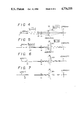
  • the adjustment of the knob 45 allows the variator lens 43 to be displaced to adjust the spot diameter of the laser beam, as described in conjunction with FIGS. 4 to 7.

Abstract

Disclosed is a laser spot projector for use with a laser coagulation system in which a laser beam is radiated as a focussed spot into a portion selected to be thermally coagulated. A laser source produces a laser beam, and a focussing lens focusses the laser beam on the selected portion in the form of a focussed laser beam spot. A variator lens is displaceably arranged between the laser source and focussing lens for changing the magnification of the laser spot depending upon the displacement of the variator lens. The variator lens is selectably displaceable to two separate positions where the image point is conjugated with the object point with respect to the variator lens. This arrangement makes it possible to selectably provide two focussed laser beam spots each having a different spot diameter.

Description

BACKGROUND OF THE INVENTION
1. Field of the Invention
This invention relates to a laser spot projector, and more particularly to a laser spot projector for use with a laser coagulation system in which a laser beam is radiated as a spot into a portion selected to be thermally coagulated.
2. Description of the Prior Art
There have long been known laser coagulation systems in which during an ophthalmic operation against diseases such as retina detachment, glaucoma, etc., a patient's eye is irradiated with laser energy, which is absorbed by a biological organism such as retina to develop thermal coagulation thereon for ophthalmological treatment. For this purpose, the laser coagulation system includes a laser spot projector for producing a laser beam from an argon or krypton laser, which is condensed to a laser beam spot of a predetermined diameter, directed toward a predetermined portion of the eyeball to be coagulated, and then focussed thereon as a laser spot for thermally coagulating the portion selected.
The laser coagulation system further comprises a slit image projector for forming a slit image on the eyeball to illuminate the background and to define the predetermined portion of the eyeball to be coagulated, and an observation equipment for observing the slit image and laser spot in the eyeball.
In such an arrangement, the laser spot from the laser spot projector must be changed in diameter depending upon how large the portion to be coagulated is. To adjust the diameter of the laser spot, the laser spot projector is conventionally provided with a magnification changing device of a type which has already been used in the field of the laser beam machining.
However, such a laser spot projector in the prior art has the drawbacks that the magnification changing device is complicated in structure, not compact and very hard to operate.
SUMMARY OF THE INVENTION
It is therefore an object of the present invention to provide a laser spot projector capable of easily adjusting the magnification of the laser spot projected on the portion to be thermally coagulated.
It is another object of the present invention to provide a laser spot projector capable of being made compact, and easy to manufacture.
A laser spot projector according to the present invention comprises a laser source for producing a laser beam, a focussing lens for focussing the laser beam on a selected portion in the form of a laser spot, and a variator lens displaceably arranged between the laser source and focussing lens for changing the magnification of the laser spot depending upon the displacement thereof. The variatior lens is displaceable to a position such that object and image points of the variator lens lie at its conjugate points.
The variator lens is thus displaceable to a first position where a laser beam aperture at the object point is focussed to form the aperture image at the image point corresponding to one of the conjugate points of the variator lens, thus forming a laser spot having a first diameter. The variator lens is also displaceable to a second position such that the conjugate point at which the image point lies is reversed to an object point of the variator lens. Accordingly a laser spot having a second diameter different from the first diameter can be formed at the same image point. Thus, the laser spot projector of the present invention makes it possible to provide two sizes of focussed laser spot each having a different spot diameter.
According to the preferred embodiment of the present invention, the variator lens is further displaceable to a position where the object or image point of the variator lens lies out of the conjugate points. In this position, the laser spot can be adjusted to any magnification although the laser spot is not focussed.
BRIEF DESCRIPTION OF THE DRAWINGS
The objects and features of the present invention will become more apparent from a consideration of the following detailed description taken in conjunction with the accompanying drawings in which:
FIG. 1 is a perspective view showing a whole appearance of a laser coagulation system of the present invention;
FIG. 2 is an illustrative view showing the arrangement of an optical system for a laser spot projector, slit image projector and observation equipment used in the laser coagulation system of the present invention;
FIG. 3 is a perspective view showing the arrangement of the optical system in FIG. 2; and
FIGS. 4 to 7 are illustrative views each showing how the laser beam can be focussed depending upon the position of a variator lens used in the laser spot projector of the invention.
DETAILED DESCRIPTION OF THE PREFERRED EMBODIMENTS
FIG. 1 shows the appearance of a laser coagulation system including a laser spot projector according to the present invention. The laser coagulation system 1 includes a slider 11 mounted on a base plate 10 so as to be slidable relative to the base plate 10 in a direction X or Y by means of a manipulator 12 such as a joy stick. The displacement of the slider 11 relative to the base plate 10 can be effected by operating the manipulator 12 in the directions X and Y. The slider 11 supports thereon an instrument base 53 on which a slit image projector 20, a laser spot projector 21 and an observation equipment 50 are mounted as will be fully described later. The manipulator 12 is further provided with a handle 12a, the rotation of which allows the instrument base 53 to move upwardly or downwardly to displace the projectors 20 and 21 together with the observation equipment 50 vertically. Thus, the manipulator 12 can adjust the position of the instrument base 53 in the directions X and Y and in the vertical direction. The thus adjusted slider 11 can be locked on the base plate 10 by means of a lock 12b.
The base plate 10 has on its front edge two poles 13 between which a chin support 14 and a forehead pad 15 are fixedly mounted. A patient sits down in front of the apparatus with his chin on the support 14 and his forehead against the pad 15 and watches an eye fixation lamp 16a which serves to fix the patient's eye during measurement or coagulation.
Mounted on the rear end of the slider 11 is the slit image projector 20 which is turnable about the axis A (see FIG. 2) and serves to project a slit image onto the eyeball to illuminate the background and determine the portion of the eye to be measured or coagulated. As will be described later, the slit image projector 20 is arranged coaxially with the laser spot projector 21 for projecting a laser beam from a source 40 such as an argon or krypton laser through an optical fiber 41 onto that portion to be coagulated in the eyeball. The observation equipment 50 for observing the focussed laser spot or imaged slit in the eyeball is further arranged on the front edge of the slider 11 so as to be rotatable about the same axis as the turning axis A for the slit image projector 20.
FIGS. 2 and 3 show the detailed arrangement of an optical system for the laser spot projector 21, slit image projector 20 and observation equipment 50. The slit image projector 20 is arranged in a housing 22 mounted so as to be rotatable about the axis A and is provided therein with a lamp 24 which is adjustable in intensity by means of an adjusting knob 23 (see FIG. 1). The lamp 24 emits illuminating light, which is converged by condenser lenses 25 and 25' to illuminate a slit aperture 26. Arranged between the condenser lens 25 and slit aperture 26 are a roof-shaped prism 27, an infrared ray cutting filter 28 and a detachable blue filter 29. The illuminated slit aperture 26 is imaged, for example, onto a retain 34 of a patient's eye 33 as a slit image 34' by means of a focussing lens 30 including lenses 30a and 30b. To eliminate the imaging function of the eye itself, a special contact lens(not shown) is attached to the patient's eye. A mirror assembly 35 having three-divided mirror portions 35a to 35c is mounted between the patient's eye 33 and lens 30b. The central mirror portion 35b can, as described later, be turned upwardly, downwardly, leftwardly or rightwardly about an axis perpendicular to or lying on the paper surface (in FIG. 2) by means of an operating lever 12c of the manipulator 12.
Arranged between the lens 30a and a prism 31 is a screen plate 36 which serves to interrupt the arrival of slit light to the central mirror 35a, while permitting it to reach the upper and lower mirrors 35b, 35c to the retina 34. To make the slit image on the retina 34 brighter and sharper, the deflection prism 27 has one surface 27a angled to deflect light toward the lower mirror 35b and the other surface 27b also angled to deflect light toward the upper mirror 35c. Thus, the deflection prism 27 functions to form the filament image of the lamp 24 at two points existing on the entrance pupil of the focussing lens 30.
It is to be noted that the slit width and length of the slit aperture 26 are adjustable by adjusting knobs 37 and 38 and the intensity of the lamp 24 are adjustable by an adjusting knob 23.
The laser spot projector 21 is, on the other hand, arranged in the same housing 22 as the slit image projector 20. The laser beam passing through the optical fiber 41 from the laser source 40 is deflected rectangularly at a prism 42 toward a variator lens 43 and a lens 44, reflected at the prism 31 and then advanced along the same optical path as the slit image projector 20 through the lens 30b, mirror 35a and the contact lens (not shown) to radiate the laser spot of a predetermined diameter on the retina 34 for thermal coagulation. The spot diameter of the laser beam can be adjusted in the range of about 50 μm to 1 mm by turning a knob 45 and adjusting the variator lens 43.
The instrument base 53 (FIG. 1) is provided with the housing 22 for accommodating the projectors 20 and 21 and a housing 52 for accommodating the observation equipment 50, and is displaceable vertically by using the handle 12a of the manipulator 12 as mentioned before. Further, the housings 22 and 52 are turnable to each other about the axis A, so that the projectors 20, 21 and the observation equipment 50 can undergo upward, downward or turning movement, respectively. The observation equipment 50 includes an optical system comprised of an objective lens 55, variator lenses 56 and 56', a safety filter 61, a focussing lens 57, erecting prisms 58 and 58', and eyepieces 51, 51'. The observation equipment 50 allows the observation of the slit image and laser spot formed in the eyeball. The adjustment of a knob 60 causes the variator lens 56 to be adjusted to provide an enlarged or reduced slit image or laser spot. The safety filter 61 is used to interrupt the laser beam reflected back from the irradiated portion of eye or cornea and to protect the eyes of an observer. For this purpose, the safety filter 61 is automatically inserted into the optical path of the observation equipment 50 immediately before the laser source 40 is activated to produce a stronger laser beam.
It should be noted that the optical elements following the objective lens 55 are provided in pairs respectively to allow binocular observation.
FIGS. 4 to 7 show a main portion of the laser spot projector 21.
For an optical system where a laser beam emitted from an aperture of the optical fiber 41 disposed at a point A is repeatedly reflected or refracted and focussed to form an aperture image at a point A', the point A is commonly designated as an object point and the point A' as an image point. If the laser beam or light is caused to advance reversely from the image point A', then the light is focussed on the object point A. In this case, the point A serves as the image point and the point A' as the object point, so that the object and image points are exchangeable in its function. It this connection, a pair of object and image points are called conjugate points, respectively.
In the case of the embodiment in FIG. 4, the top edge of the fiber 41 forms the aperture disposed at the object point to form an aperture image with respect to the image forming means in the form of a variator lens 43, and a point A' at which an aperture image is formed is the image point measured from the variator lens 43. Thus, the distance between the points A and A' is kept the same even if the variator lens 43 is selectably displaced from one position to the other separate position to have its conjugate points reversed, for example, as shown in FIG. 5.
Now assume that a point A" is a focal point which exists on the retina and coincides with a treatment point and on which the aperture image is focussed by the focussing lens 44 and 30 through the variator lens 43. When the variator lens 43 is placed in one specific position as shown in FIG. 4, the magnification rate of the variator lens 43 is calculated as A'/A=0.707. Accordingly, the aperture A of 60 μm diameter
at the object point A is imaged by the variator lens 43 to form the aperture image having a reduced diameter of 42.42 μm at the image point A'. The focussing lenses 44 and 30 are disposed between the image point A' and a treatment point A" to determine the magnification rate thereof A"/A'=1.179 and then causes the formation of a focussed aperture image having a diameter of 50μum at the treatment point
If, on the other hand, the variator lens 43 is shifted toward the object point A as shown in FIG. 5 in the reversed position with respect to the object and image points A and A' as shown in FIG. 5, then the magnification rate of the variator lens 43 A'/A is equal to 1.414. Accordingly, the variator lens 43 forms the aperture image of 84.84 μm diameter at the common image point A' and a laser beam spot having a diameter of 100 μm on is focused the treatment point A". Since the focussing lenses 44 and 30 has the same magnification rate A"/A'=1.179.
Thus, the utilization of the conjugated relation between the object and image points in the optical system allows the formation of a focussed clear spot image.
If the variator lens 43 is further displaced toward the object point A out of its conjugation, then the spot image on the treatment point A" becomes blurred or defocussed and has a diameter of 500 μm or 1000 μm, for example, as shown in FIGS. 6 and 7. This makes it possible to produce a spot image having any diameter, although it appears to be out of focus.
It is to be noted that an operating lever may be provided in the housing or lens barrel to displace or adjust the variator lens 43 in accordance with a scale provided thereon.
The operation of the laser coagulation system according to the present invention will now be described.
The patient first sits down with his chin on the support 14 and his forehead against the pad 15 and pays the watches the eye fixation lamp 16. The lamp 24 of the slit image projector 20 is then turned on to form the slit image 34' on the retina 34 of the patient's eye 33 through the contact lens set thereon. The slit light has its central flux inhibited to arrive at the central mirror 35a by means by the screen plate 36 and is reflected only at the upper and lower mirrors 35b and 35c to form the slit image 34' on the retina 34. In this case, the deflection prism 27 is used to deflect the slit light towards the mirrors 35b and 35c effectively. The intensity of the slit image can be adjusted by the knob 23, and the slit width and length can be adjusted by the adjusting knobs 37 and 38.
If the slit image 34' deviates from the desired place in the above-mentioned slit image formation, the manipulator 12 may be operated to displace the slider 11 and the housings 22 and 52 in the directions X, Y and Z and turn the projectors 20, 21 or observation equipment 50 about the axis A relative to each other until the slit image is formed on the desired portion for coagulation.
The thus formed slit image 34' can be observed by the optical system of the observation equipment including the objective lens 55, variator lens 56, imaging lens 57, erecting prism 58 and eyepiece 51. After the portion of eye to be coagulated has been determined, the laser source 40 is activated to emit a week laser beam, which is caused to pass through the prism 42, variator lens 43, lens 44, prism 31, and lens 30b, reflected at the central mirror 35a and then focussed as a spot onto the retina 34. For coagulation, a stronger laser beam is generated from the laser source 40 by changing power. When the stronger beam is activated, the safety filter is automatically inserted into the optical path of the observation equipment 50 to protect the eyes of the observer from the laser beam reflected from the irradiated portion of the patient's eye or retina.
For fine and precise coagulation the laser spot on the retina 34 can be displaced by scanning the central mirror 35a vertically or horizontally, that is, in the direction X or Y using the operating lever 12c of the manipulator 12.
The adjustment of the knob 45 allows the variator lens 43 to be displaced to adjust the spot diameter of the laser beam, as described in conjunction with FIGS. 4 to 7.
It will also appreciated that the variator lens 43 may comprise not only one lens, but also a plurality of lenses and/or reflecting means such as mirrors for deflecting the optical path.
While the invention has been described with reference to a preferred embodiment, it will be understood by those skilled in the art that various changes may be made and equivalents may be substituted for elements thereof without departing from the scope of the invention. In addition, many modifications may be made to adapt a particular situation or material to the teachings of the invention without departing from the essential scope thereof. Therefore, it is intended that the invention should not be limited to the particular embodiment disclosed as the best mode contemplated for carrying out the invention, but that the invention will include all embodiments falling within the scope of the appended claims.

Claims (10)

We claim:
1. An apparatus for ophthalmic laser treatment of the eye of a patient, comprising: slit image projecting means for producing a slit of light and projecting a slit image into the eye of a patient to illuminate the eye to enable a determination as to the treatment portion of the eye to be treated, the slit image projecting means including a source of light, and means for forming the light from the light source into a slit image composed of two slit image components; laser beam projecting means for projecting a laser beam into the eye of the patient for treating the eye; wherein both the slit image projecting means and the laser beam projecting means include a common reflecting means for selectively reflecting the slit image and the laser beam toward the eye, the common reflecting means having two side portions positioned to reflect and direct the respective slit image components toward the eye to illuminate the eye to thereby determine the treatment portion, and a central portion positioned to reflect and direct the laser beam toward the determined treatment portion to treat the eye; and wherein the laser beam projecting means includes a laser source for producing the laser beam, a focussing lens for focussing the laser beam on the determined treatment portion of the eye in the form of a focussed laser spot, and a variator lens displaceably arranged between the laser source and focussing lens for changing the magnification of the focussed laser spot according to the position of the variator lens, the variator lens being displaceable to a first position such that its object point corresponds to one conjugate point of the variator lens and its image point corresponds to the other conjugate point thereof with the object and image points spaced apart a given axial distance from one another so that the focussing lens forms a first focussed laser spot on the determined treatment portion, and being displaceable to a second position such that its object point corresponds to the other conjugate point and its image point corresponds to said one conjugate point while maintaining the given axial distance between the object and image points so that the focussing lens forms on the determined treatment portion a second focussed laser spot having a spot diameter different from that of the first focussed laser spot.
2. An apparatus according to claim 1; wherein the laser beam projecting means includes means for holding the focussing lens at a fixed distance with respect to the determined treatment portion of the eye.
3. An apparatus according to claim 1; wherein the slit image projecting means includes a condenser lens for condensing the light from the source of light, and a deflection prism arranged between the condenser lens and the means for forming the slit image and having a roof-shaped surface, one half of which serves to deflect the condensed light toward one side portion of the common reflecting means through the means for forming the slit image, and the other half of which serves to deflect the condensed light toward the other side portion of the common reflecting means through the means for forming the slit image.
4. A laser spot projector for use with a laser coagulation system in which a laser beam is radiated as a spot onto a selected portion of an area to be thermally coagulated, the laser spot projector comprising:
a laser source for producing a laser beam;
a focussing lens for focussing said laser beam on a selected portion of an area in the form of a laser spot; and
a variator lens displaceably arranged between said laser source and focussing lens for changing the magnification of said laser spot according to the position of the variator lens, said variator lens being displaceable to a first position such that its object point corresponds to one conjungate point of said variator lens and its image point corresponds to the other conjugate point thereof with the object and image points spaced apart a given axial distance from one another so that the focussing lens forms a first focussed laser spot on said selected portion, and being displaceable to a second position such that its object point corresponds to the other conjugate point and its image point corresponds to said one conjugate point while maintaining the given axial distance between the object and image points so that the focussing lens forms a second focussed laser spot having a spot diameter different from that of said first focussed laser spot.
5. A laser spot projector according to claim 4 including means for holding said focussing lens at a fixed distance with respect to the position of said selected portion.
6. An apparatus for directing a laser beam along an optical axis to a treatment point for use during a surgical operation, comprising: emitting means having means defining an aperture disposed at a definite object point on an optical axis for emitting a laser beam from the aperture along the optical axis; image forming means selectively displaceable along the optical axis to one of two selected positions for selectively forming two aperture images different in size according to the selected position of the image forming means at a common image point conjugated with the object point with respect to the image forming means to thereby maintain the axial distances between the aperture and one of the two aperture images and between the aperture and the other of the two aperture images equal to each other; and focussing means disposed between the common image point and the treatment point on the optical axis for focussing the aperture image selectively formed at the common image point onto the treatment point to form thereon a corresponding focussed aperture image so that the laser beam travelling along the optical axis is irradiated onto the treatment point in the form of a focussed spot which corresponds to the focussed aperture image and which has a size determined according to the selected position of the image forming means.
7. An apparatus according to claim 6 wherein the emitting means includes an optical fiber for transmitting therethrough the laser beam, the optical fiber having a top edge defining an aperture for emitting therefrom the transmitted laser beam.
8. An apparatus according to claim 6 wherein the image forming means comprises a variator lens operative when placed in one of the two selected positions to form an enlarged aperture image and operative when placed in the other selected position to form a reduced aperture image.
9. An apparatus according to claim 8 wherein the focussing means comprises an objective lens for magnifying the enlarged and reduced aperture images with the same rate.
10. An apparatus according to claim 9 wherein the objective lens is positioned a fixed distance from the treatment point.
US06/919,319 1985-10-18 1986-10-14 Laser spot projector Expired - Lifetime US4776335A (en)

Applications Claiming Priority (2)

Application Number Priority Date Filing Date Title
JP60-231316 1985-10-18
JP60231316A JPS6291913A (en) 1985-10-18 1985-10-18 Laser spot optical system

Publications (1)

Publication Number Publication Date
US4776335A true US4776335A (en) 1988-10-11

Family

ID=16921721

Family Applications (1)

Application Number Title Priority Date Filing Date
US06/919,319 Expired - Lifetime US4776335A (en) 1985-10-18 1986-10-14 Laser spot projector

Country Status (4)

Country Link
US (1) US4776335A (en)
EP (1) EP0230094B1 (en)
JP (1) JPS6291913A (en)
DE (1) DE3679898D1 (en)

Cited By (14)

* Cited by examiner, † Cited by third party
Publication number Priority date Publication date Assignee Title
US5152760A (en) * 1989-03-17 1992-10-06 The General Hospital Corporation Non-invasive sclerostomy
US5171242A (en) * 1990-10-26 1992-12-15 Coherent, Inc. Combination lens system for retinal photocoagulator laser system
US5226903A (en) * 1991-01-30 1993-07-13 Nidek Co., Ltd. Apparatus for ophthalmic operation using photocoagulation by a laser beam
US5290272A (en) * 1992-03-16 1994-03-01 Helios Inc. Method for the joining of ocular tissues using laser light
US5336216A (en) * 1991-10-10 1994-08-09 Coherent, Inc. Apparatus for delivering a defocused laser beam having a sharp-edged cross-section
US5342351A (en) * 1992-08-19 1994-08-30 Carl Zeiss-Stiftung Beam positioning device for an ophthalmological instrument
US5400791A (en) * 1991-10-11 1995-03-28 Candela Laser Corporation Infrared fundus video angiography system
US5425729A (en) * 1985-10-18 1995-06-20 Kowa Company Ltd. Laser coagulation system
US5643249A (en) * 1992-02-14 1997-07-01 Nidek Co., Ltd. Optical ophthalmic treatment apparatus
US6576866B1 (en) * 1998-09-17 2003-06-10 Siemens And Shell Solar Gmbh Method for structuring transparent electrode layers
US20080212036A1 (en) * 2007-03-01 2008-09-04 Sanyo Electric Co., Ltd. Projection Type Color Projector
US20130167385A1 (en) * 2007-05-04 2013-07-04 Leica Geosystems Ag Control method for producing ground markings, and reference beam generator
CN107608073A (en) * 2017-09-30 2018-01-19 天逸瑞狮(苏州)口腔医疗科技股份有限公司 Image-scanning system and its laser beam module
USD816218S1 (en) * 2014-10-30 2018-04-24 Kowa Company, Ltd. Anterior ocular segment observation device

Families Citing this family (6)

* Cited by examiner, † Cited by third party
Publication number Priority date Publication date Assignee Title
EP0397777A1 (en) * 1988-01-25 1990-11-22 Refractive Laser Research And Development, Inc. Method and apparatus for laser surgery
DE3830378C2 (en) * 1988-09-07 1997-11-27 Zeiss Carl Fa Ophthalmic device
HU900200D0 (en) * 1989-01-20 1990-03-28 Mezhotras Nt Mikrokhir Glaza Equipment for surgical treatment of ametropia
JPH0396820U (en) * 1990-01-24 1991-10-03
SI22509A (en) * 2007-04-11 2008-10-31 Optotek D.O.O. Optical system for selective laser trabeculoplastics
CN113974957B (en) * 2021-11-02 2023-11-17 北京鹰瞳科技发展股份有限公司 Lens barrel for fundus massage device and fundus massage device

Citations (7)

* Cited by examiner, † Cited by third party
Publication number Priority date Publication date Assignee Title
FR860192A (en) * 1939-06-16 1941-01-08 Levallois Optique Et Prec Collimator refinements
DE2441294A1 (en) * 1973-09-04 1975-03-13 Xerox Corp VARIO LENS, IN PARTICULAR FOR USE BETWEEN FIXED CONJUGATED LEVELS
US4397310A (en) * 1981-02-27 1983-08-09 The Government Of The United States Of America As Represented By The Secretary Of Department Of Health And Human Services Anastigmatic high magnification, wide-angle binocular indirect attachment for laser photocoagulator
US4520816A (en) * 1983-01-12 1985-06-04 Schachar Ronald A Method and apparatus for delivering laser energy for ophthalmic use
US4538608A (en) * 1984-03-23 1985-09-03 Esperance Jr Francis A L Method and apparatus for removing cataractous lens tissue by laser radiation
US4554917A (en) * 1982-04-01 1985-11-26 Essilor International Cie Generale D'optique Laser ophthalmological surgical device
US4628416A (en) * 1985-05-03 1986-12-09 Coopervision, Inc. Variable spot size illuminator with constant convergence angle

Family Cites Families (8)

* Cited by examiner, † Cited by third party
Publication number Priority date Publication date Assignee Title
US3096767A (en) * 1961-05-11 1963-07-09 Trg Inc Photo-cauterizer with coherent light source
DE1197579B (en) * 1963-06-14 1965-07-29 Zeiss Carl Fa Optical device for coagulation inside the eye for radiation sources with a small opening angle
US3348547A (en) * 1964-10-16 1967-10-24 American Optical Corp Photocoagulating apparatus
FR1523270A (en) * 1967-03-10 1968-05-03 Lunetiers Portable photocoagulator
US3703176A (en) * 1970-05-28 1972-11-21 Arthur Vassiliadis Slit lamp photocoagulator
US3769963A (en) * 1972-03-31 1973-11-06 L Goldman Instrument for performing laser micro-surgery and diagnostic transillumination of living human tissue
JPS55151612A (en) * 1979-05-15 1980-11-26 Canon Inc Zoom expander
DE3339369A1 (en) 1983-10-29 1985-05-09 Meditec GmbH, 8501 Heroldsberg NEODYM-YAG LASER, IN PARTICULAR FOR OPHTALMOLOGICAL TREATMENT

Patent Citations (7)

* Cited by examiner, † Cited by third party
Publication number Priority date Publication date Assignee Title
FR860192A (en) * 1939-06-16 1941-01-08 Levallois Optique Et Prec Collimator refinements
DE2441294A1 (en) * 1973-09-04 1975-03-13 Xerox Corp VARIO LENS, IN PARTICULAR FOR USE BETWEEN FIXED CONJUGATED LEVELS
US4397310A (en) * 1981-02-27 1983-08-09 The Government Of The United States Of America As Represented By The Secretary Of Department Of Health And Human Services Anastigmatic high magnification, wide-angle binocular indirect attachment for laser photocoagulator
US4554917A (en) * 1982-04-01 1985-11-26 Essilor International Cie Generale D'optique Laser ophthalmological surgical device
US4520816A (en) * 1983-01-12 1985-06-04 Schachar Ronald A Method and apparatus for delivering laser energy for ophthalmic use
US4538608A (en) * 1984-03-23 1985-09-03 Esperance Jr Francis A L Method and apparatus for removing cataractous lens tissue by laser radiation
US4628416A (en) * 1985-05-03 1986-12-09 Coopervision, Inc. Variable spot size illuminator with constant convergence angle

Cited By (16)

* Cited by examiner, † Cited by third party
Publication number Priority date Publication date Assignee Title
US5425729A (en) * 1985-10-18 1995-06-20 Kowa Company Ltd. Laser coagulation system
US5152760A (en) * 1989-03-17 1992-10-06 The General Hospital Corporation Non-invasive sclerostomy
US5171242A (en) * 1990-10-26 1992-12-15 Coherent, Inc. Combination lens system for retinal photocoagulator laser system
US5226903A (en) * 1991-01-30 1993-07-13 Nidek Co., Ltd. Apparatus for ophthalmic operation using photocoagulation by a laser beam
US5336216A (en) * 1991-10-10 1994-08-09 Coherent, Inc. Apparatus for delivering a defocused laser beam having a sharp-edged cross-section
US5400791A (en) * 1991-10-11 1995-03-28 Candela Laser Corporation Infrared fundus video angiography system
US5643249A (en) * 1992-02-14 1997-07-01 Nidek Co., Ltd. Optical ophthalmic treatment apparatus
US5290272A (en) * 1992-03-16 1994-03-01 Helios Inc. Method for the joining of ocular tissues using laser light
US5342351A (en) * 1992-08-19 1994-08-30 Carl Zeiss-Stiftung Beam positioning device for an ophthalmological instrument
US6576866B1 (en) * 1998-09-17 2003-06-10 Siemens And Shell Solar Gmbh Method for structuring transparent electrode layers
US20080212036A1 (en) * 2007-03-01 2008-09-04 Sanyo Electric Co., Ltd. Projection Type Color Projector
US20130167385A1 (en) * 2007-05-04 2013-07-04 Leica Geosystems Ag Control method for producing ground markings, and reference beam generator
US9528818B2 (en) * 2007-05-04 2016-12-27 Beamrider Limited Control method for producing ground markings, and reference beam generator
USD816218S1 (en) * 2014-10-30 2018-04-24 Kowa Company, Ltd. Anterior ocular segment observation device
CN107608073A (en) * 2017-09-30 2018-01-19 天逸瑞狮(苏州)口腔医疗科技股份有限公司 Image-scanning system and its laser beam module
CN107608073B (en) * 2017-09-30 2024-01-19 天逸瑞狮(苏州)口腔医疗科技股份有限公司 Image scanning system and laser beam module thereof

Also Published As

Publication number Publication date
EP0230094A1 (en) 1987-07-29
EP0230094B1 (en) 1991-06-19
DE3679898D1 (en) 1991-07-25
JPS6291913A (en) 1987-04-27

Similar Documents

Publication Publication Date Title
US4776335A (en) Laser spot projector
US4736744A (en) Laser coagulation system
US5425729A (en) Laser coagulation system
JP3206923B2 (en) Ophthalmic laser surgery device
US4638801A (en) Laser ophthalmic surgical system
US5997141A (en) System for treating the fundus of an eye
US3703176A (en) Slit lamp photocoagulator
JP3165144B2 (en) Binocular indirect mirror laser treatment system
US4759360A (en) Laser coagulation system
US6238385B1 (en) Laser treatment apparatus
US7628490B2 (en) Slit lamp microscope and ophthalmic laser treatment apparatus with the microscope
US4397310A (en) Anastigmatic high magnification, wide-angle binocular indirect attachment for laser photocoagulator
JPH08501227A (en) Method and apparatus for exposing the human eye with a controlled radiation pattern
WO1991001703A1 (en) Photocoagulation apparatus
US4526449A (en) Optical system for illuminated viewing instruments
US4786161A (en) Apparatus for examination and surgery of the anterior and posterior portions of the eye
US5243368A (en) Ophthalmologic apparatus
JP2971479B2 (en) Ophthalmic equipment
GB2143052A (en) Laser ophthalmic surgical system
JPH06205741A (en) Ophthalmological system
JPH036813B2 (en)
JP3264990B2 (en) Corneal endothelial cell imaging device
JP3255711B2 (en) Fundus camera
JP2585646B2 (en) Laser therapy equipment
JPH07236652A (en) Ophthalmic surgery device

Legal Events

Date Code Title Description
AS Assignment

Owner name: KOWA COMPANY LTD., 6-29, NISHIKI 3-CHOME NAKA-KU,

Free format text: ASSIGNMENT OF ASSIGNORS INTEREST.;ASSIGNORS:NAKANISHI, TAKAJI;HENNINGS, DAVID R.;NIINO, MASAO;REEL/FRAME:004817/0785

Effective date: 19861027

Owner name: COHERENT INCORPORATE, 3210 PORTER DRIVE, PALO ALTO

Free format text: ASSIGNMENT OF ASSIGNORS INTEREST.;ASSIGNORS:NAKANISHI, TAKAJI;HENNINGS, DAVID R.;NIINO, MASAO;REEL/FRAME:004817/0785

Effective date: 19861027

STCF Information on status: patent grant

Free format text: PATENTED CASE

FEPP Fee payment procedure

Free format text: PAYOR NUMBER ASSIGNED (ORIGINAL EVENT CODE: ASPN); ENTITY STATUS OF PATENT OWNER: LARGE ENTITY

FPAY Fee payment

Year of fee payment: 4

FPAY Fee payment

Year of fee payment: 8

FPAY Fee payment

Year of fee payment: 12

AS Assignment

Owner name: BANK HAPOALIM B.M., ISRAEL

Free format text: SECURITY INTEREST;ASSIGNOR:ESC MEDICAL SYSTEMS INC.;REEL/FRAME:011846/0061

Effective date: 20010413

Owner name: ESC MEDICAL SYSTEMS, INC., MASSACHUSETTS

Free format text: ASSIGNMENT OF ASSIGNORS INTEREST;ASSIGNOR:COHERENT, INC.;REEL/FRAME:011846/0115

Effective date: 20010427

AS Assignment

Owner name: LUMENIS INC., MASSACHUSETTS

Free format text: CHANGE OF NAME;ASSIGNOR:ESC MEDICAL SYSTEMS INC.;REEL/FRAME:011911/0540

Effective date: 20010425