US4777832A - Liquid level sensor, used in an automatic station for preparing immunologic dosages - Google Patents
Liquid level sensor, used in an automatic station for preparing immunologic dosages Download PDFInfo
- Publication number
- US4777832A US4777832A US06/930,642 US93064286A US4777832A US 4777832 A US4777832 A US 4777832A US 93064286 A US93064286 A US 93064286A US 4777832 A US4777832 A US 4777832A
- Authority
- US
- United States
- Prior art keywords
- sensor
- pressure
- output signal
- operated
- liquid level
- Prior art date
- Legal status (The legal status is an assumption and is not a legal conclusion. Google has not performed a legal analysis and makes no representation as to the accuracy of the status listed.)
- Expired - Lifetime
Links
Images


Classifications
-
- G—PHYSICS
- G01—MEASURING; TESTING
- G01N—INVESTIGATING OR ANALYSING MATERIALS BY DETERMINING THEIR CHEMICAL OR PHYSICAL PROPERTIES
- G01N35/00—Automatic analysis not limited to methods or materials provided for in any single one of groups G01N1/00 - G01N33/00; Handling materials therefor
- G01N35/10—Devices for transferring samples or any liquids to, in, or from, the analysis apparatus, e.g. suction devices, injection devices
- G01N35/1081—Devices for transferring samples or any liquids to, in, or from, the analysis apparatus, e.g. suction devices, injection devices characterised by the means for relatively moving the transfer device and the containers in an horizontal plane
- G01N35/109—Devices for transferring samples or any liquids to, in, or from, the analysis apparatus, e.g. suction devices, injection devices characterised by the means for relatively moving the transfer device and the containers in an horizontal plane with two horizontal degrees of freedom
-
- G—PHYSICS
- G01—MEASURING; TESTING
- G01F—MEASURING VOLUME, VOLUME FLOW, MASS FLOW OR LIQUID LEVEL; METERING BY VOLUME
- G01F23/00—Indicating or measuring liquid level or level of fluent solid material, e.g. indicating in terms of volume or indicating by means of an alarm
- G01F23/22—Indicating or measuring liquid level or level of fluent solid material, e.g. indicating in terms of volume or indicating by means of an alarm by measuring physical variables, other than linear dimensions, pressure or weight, dependent on the level to be measured, e.g. by difference of heat transfer of steam or water
- G01F23/24—Indicating or measuring liquid level or level of fluent solid material, e.g. indicating in terms of volume or indicating by means of an alarm by measuring physical variables, other than linear dimensions, pressure or weight, dependent on the level to be measured, e.g. by difference of heat transfer of steam or water by measuring variations of resistance of resistors due to contact with conductor fluid
- G01F23/241—Indicating or measuring liquid level or level of fluent solid material, e.g. indicating in terms of volume or indicating by means of an alarm by measuring physical variables, other than linear dimensions, pressure or weight, dependent on the level to be measured, e.g. by difference of heat transfer of steam or water by measuring variations of resistance of resistors due to contact with conductor fluid for discrete levels
-
- G—PHYSICS
- G01—MEASURING; TESTING
- G01N—INVESTIGATING OR ANALYSING MATERIALS BY DETERMINING THEIR CHEMICAL OR PHYSICAL PROPERTIES
- G01N35/00—Automatic analysis not limited to methods or materials provided for in any single one of groups G01N1/00 - G01N33/00; Handling materials therefor
- G01N35/10—Devices for transferring samples or any liquids to, in, or from, the analysis apparatus, e.g. suction devices, injection devices
- G01N35/1009—Characterised by arrangements for controlling the aspiration or dispense of liquids
- G01N2035/1025—Fluid level sensing
Definitions
- the present invention relates to auxiliary devices for automatic equipment, particularly liquid level sensors.
- the invention relates to a liquid level sensor suitable as an auxiliary device in an automatic station for preparing immunologic dosages.
- One phase is the suction, from several containers or test tubes, of liquids containing the reagents, and subsequently the dispensing of these liquids into the test tubes where the reactions are to take place.
- a typical automatic station consists of a computer controlling the operation of:
- a diluter connected to the probe, for suctioning and dispensing the liquids.
- the diluter is normally made up by one or more syringes, connected by means of flexible tubes, to the probe of the plotter.
- the suction and dispensing operations are carried out by moving the syringe piston up or down.
- the plotter probe is called usually z-axis, and has no fixed needle, but uses tips which, at intervals, are taken from a suitable tray and automatically changed after each dispensing operation, so as to avoid any possible contamination.
- the tip collects several times from the same test tube (or container) well determined quantities of the liquid to be dispensed.
- This system permits the computer to know the level, and therefore the volume, of the liquid contained in the test tube. If the quantity of liquid is sufficient to satisfy the request, the computer can at this point lower the tip with reference to the free surface of the liquid, to a depth corresponding to the volume of liquid to be withdrawn, thus avoiding lowering the tip more than necessary.
- the operation could be even more refined by performing in subsequent steps, small immersions of the tip with alternate suctioning of small volumes of liquid until the total volume to be withdrawn has been reached; in this manner only a small portion of the tip is maintained immersed in the liquid.
- the sensors more commonly used to detect liquid levels are the capacity and resistivity types. Capacity sensors detect the difference in the dielectric constant, and therefore the capacity, when there are variations in the media in which they are immersed.
- the resistivity sensors make use of the conductivity of the liquid in which they are immersed, which short-circuits the two electric contacts.
- a typical automatic station for preparing immunologic dosages includes a computer which controls the operations of a plotter for positioning a dispensing probe on a working surface containing the dosage trays, and a diluter, connected to the probe, for the suction and dispensing of the liquids.
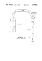
- FIGS. 1 and 2 show a theoretical solution of the problem of detecting a liquid level with the necessary degree of sensitivity by using a pressure transducer.
- FIG. 1 shows the situation wherein the tip of the z-axis is not in contact with the liquid; in this case the air flows from the orifice of the tip itself and no internal pressure is created.
- FIG. 2 shows the situation wherein the tip comes into contact with the liquid free surface in the test tube (or in the container of a reagent), in which case the orifice is immersed and consequently an overpressure is created, which activates the pressure switch.
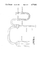
- FIGS. 3, 4 and 5 show the device according to the present invention, as such (FIG. 3), when installed in the dispensing system (FIG. 4), and when activated due to the contact of the tip with the liquid free surface (FIG. 5). These figures may be helpful in understanding the detailed description which follows.
- the liquid level sensor according to the invention consists of a U pipe containing water (FIG. 3). Both free surfaces of the water, under atmospheric pressure, are generally at the same level, according to the law of communicating containers.
- the above described device is used to detect the liquid levels in the test tubes by means of the operating connection shown in FIG. 4.
- the z-axis of the preparing station is connected, through a suitable T-member:
- a preferred form provides for the connection of the operational device according to the invention, to the dispensing system through an electrically controlled valve, place at the input of branch 1. (FIG. 4).
- the purpose of the valve is to keep the connection open only during the phase of use of the sensor level. During the other phases, i.e. during suction and dispensing of the liquids, the connection should be interrupted in order to permit a correct execution of these operations.
- the valve is automatically activated and disactivated by the computer.
- the liquid contained in the U-pipe exemplified as water, could be any liquid endowed with conductivity suitable for the resistivity sensor used.
- liquid level sensor which embodies an appropriate sensitivity together with structural simplicity, may be used as an auxiliary means in any system whereby it is necessary to determine the level of a liquid and translate it into an immediate return signal to the control unit. Therefore, its use is not limited to automatic stations for preparing immunologic dosages.
Abstract
Description
Claims (20)
Applications Claiming Priority (2)
| Application Number | Priority Date | Filing Date | Title |
|---|---|---|---|
| IT48804/85A IT1181735B (en) | 1985-11-19 | 1985-11-19 | LIQUID LEVEL SENSOR, USED IN AN AUTOMATIC STATION FOR THE PREPARATION OF IMMUNOLOGICAL DOSAGES |
| IT48804A/85 | 1985-11-19 |
Publications (1)
| Publication Number | Publication Date |
|---|---|
| US4777832A true US4777832A (en) | 1988-10-18 |
Family
ID=11268639
Family Applications (1)
| Application Number | Title | Priority Date | Filing Date |
|---|---|---|---|
| US06/930,642 Expired - Lifetime US4777832A (en) | 1985-11-18 | 1986-11-14 | Liquid level sensor, used in an automatic station for preparing immunologic dosages |
Country Status (9)
| Country | Link |
|---|---|
| US (1) | US4777832A (en) |
| EP (1) | EP0223751B1 (en) |
| JP (1) | JP2593856B2 (en) |
| AT (1) | ATE68263T1 (en) |
| CA (1) | CA1306779C (en) |
| DE (2) | DE223751T1 (en) |
| ES (1) | ES2000052T3 (en) |
| FI (1) | FI85190C (en) |
| IT (1) | IT1181735B (en) |
Cited By (16)
| Publication number | Priority date | Publication date | Assignee | Title |
|---|---|---|---|---|
| US4986782A (en) * | 1989-11-24 | 1991-01-22 | Severtson Lyndon W | Liquid flow detector system |
| US5013529A (en) * | 1987-05-02 | 1991-05-07 | Teruaki Itoh | Apparatus for distributing sample liquid |
| US5133392A (en) * | 1991-04-10 | 1992-07-28 | Eastman Kodak Company | Liquid injection using container bottom sensing |
| US5428993A (en) * | 1992-02-26 | 1995-07-04 | Toa Medical Electronics Co., Ltd. | Automatic analyzer having function of detecting remaining liquid quantity |
| US5465629A (en) * | 1992-06-08 | 1995-11-14 | Behring Diagnostics Inc. | Liquid dispensing system with acoustic sensing means |
| US5499545A (en) * | 1993-06-18 | 1996-03-19 | Sony Corporation | Pipetting device and method therefore |
| EP0810438A2 (en) * | 1996-05-31 | 1997-12-03 | Packard Instrument Company, Inc. | Microvolume liquid handling system |
| US5723795A (en) * | 1995-12-14 | 1998-03-03 | Abbott Laboratories | Fluid handler and method of handling a fluid |
| US5915282A (en) * | 1995-12-14 | 1999-06-22 | Abbott Laboratories | Fluid handler and method of handling a fluid |
| US5927547A (en) * | 1996-05-31 | 1999-07-27 | Packard Instrument Company | System for dispensing microvolume quantities of liquids |
| US5965828A (en) * | 1995-12-14 | 1999-10-12 | Abbott Laboratories | Fluid handler and method of handling a fluid |
| EP1007973A2 (en) * | 1997-04-08 | 2000-06-14 | Packard Instrument Company, Inc. | Microvolume liquid handling system |
| US6203759B1 (en) | 1996-05-31 | 2001-03-20 | Packard Instrument Company | Microvolume liquid handling system |
| US6521187B1 (en) | 1996-05-31 | 2003-02-18 | Packard Instrument Company | Dispensing liquid drops onto porous brittle substrates |
| US6537817B1 (en) | 1993-05-31 | 2003-03-25 | Packard Instrument Company | Piezoelectric-drop-on-demand technology |
| US20170314214A1 (en) * | 2016-05-02 | 2017-11-02 | Roadtec, Inc. | Spray assembly for a working machine employing direct acting valves |
Families Citing this family (5)
| Publication number | Priority date | Publication date | Assignee | Title |
|---|---|---|---|---|
| JPS63109330A (en) * | 1986-10-27 | 1988-05-14 | Kyoto Daiichi Kagaku:Kk | Method and apparatus for detecting liquid level |
| US5750881A (en) * | 1995-07-13 | 1998-05-12 | Chiron Diagnostics Corporation | Method and apparatus for aspirating and dispensing sample fluids |
| US6158269A (en) * | 1995-07-13 | 2000-12-12 | Bayer Corporation | Method and apparatus for aspirating and dispensing sample fluids |
| US5665601A (en) * | 1996-01-22 | 1997-09-09 | Johnson & Johnson Clinical Diagnostics, Inc. | Avoiding bubble formation while sensing air-liquid interface using pressurized air flow |
| US10401209B2 (en) | 2016-06-22 | 2019-09-03 | Abbott Laboratories | Liquid level sensing apparatus and related methods |
Citations (6)
| Publication number | Priority date | Publication date | Assignee | Title |
|---|---|---|---|---|
| US2423397A (en) * | 1940-10-17 | 1947-07-01 | Lavigne Jean Loumiet Et | Steam boiler regulating system |
| GB844010A (en) * | 1958-08-05 | 1960-08-10 | Cai Moeller | Improvements in or relating to liquid level control devices |
| FR1342284A (en) * | 1962-09-26 | 1963-11-08 | Liquid level indicator and regulator | |
| US3477460A (en) * | 1965-08-02 | 1969-11-11 | Mallory & Co Inc P R | Fluid level control system |
| US3687289A (en) * | 1970-09-04 | 1972-08-29 | Ecodyne Corp | Water softener system |
| US3813945A (en) * | 1971-11-19 | 1974-06-04 | Nielsen Eng & Res Inc | Apparatus for extracting a liquid sample at various depths of a liquid stream |
Family Cites Families (3)
| Publication number | Priority date | Publication date | Assignee | Title |
|---|---|---|---|---|
| DE2655303A1 (en) * | 1976-12-07 | 1978-06-08 | Walter Schweikert | Fluid flow control in bakeries - uses level sensor in supply tanks to maintain constant level and control outflow through base valve |
| JPS56164958A (en) * | 1980-05-23 | 1981-12-18 | Aloka Co Ltd | Automatic dispenser |
| JPS5952759A (en) * | 1982-09-20 | 1984-03-27 | Terumo Corp | Drawing and dispensing device for sample |
-
1985
- 1985-11-19 IT IT48804/85A patent/IT1181735B/en active
-
1986
- 1986-11-14 US US06/930,642 patent/US4777832A/en not_active Expired - Lifetime
- 1986-11-17 ES ES198686830346T patent/ES2000052T3/en not_active Expired - Lifetime
- 1986-11-17 DE DE198686830346T patent/DE223751T1/en active Pending
- 1986-11-17 AT AT86830346T patent/ATE68263T1/en not_active IP Right Cessation
- 1986-11-17 EP EP86830346A patent/EP0223751B1/en not_active Expired - Lifetime
- 1986-11-17 DE DE8686830346T patent/DE3681886D1/en not_active Expired - Lifetime
- 1986-11-17 CA CA000523105A patent/CA1306779C/en not_active Expired - Lifetime
- 1986-11-18 FI FI864697A patent/FI85190C/en not_active IP Right Cessation
- 1986-11-18 JP JP61273045A patent/JP2593856B2/en not_active Expired - Lifetime
Patent Citations (6)
| Publication number | Priority date | Publication date | Assignee | Title |
|---|---|---|---|---|
| US2423397A (en) * | 1940-10-17 | 1947-07-01 | Lavigne Jean Loumiet Et | Steam boiler regulating system |
| GB844010A (en) * | 1958-08-05 | 1960-08-10 | Cai Moeller | Improvements in or relating to liquid level control devices |
| FR1342284A (en) * | 1962-09-26 | 1963-11-08 | Liquid level indicator and regulator | |
| US3477460A (en) * | 1965-08-02 | 1969-11-11 | Mallory & Co Inc P R | Fluid level control system |
| US3687289A (en) * | 1970-09-04 | 1972-08-29 | Ecodyne Corp | Water softener system |
| US3813945A (en) * | 1971-11-19 | 1974-06-04 | Nielsen Eng & Res Inc | Apparatus for extracting a liquid sample at various depths of a liquid stream |
Cited By (23)
| Publication number | Priority date | Publication date | Assignee | Title |
|---|---|---|---|---|
| US5013529A (en) * | 1987-05-02 | 1991-05-07 | Teruaki Itoh | Apparatus for distributing sample liquid |
| US4986782A (en) * | 1989-11-24 | 1991-01-22 | Severtson Lyndon W | Liquid flow detector system |
| US5133392A (en) * | 1991-04-10 | 1992-07-28 | Eastman Kodak Company | Liquid injection using container bottom sensing |
| US5428993A (en) * | 1992-02-26 | 1995-07-04 | Toa Medical Electronics Co., Ltd. | Automatic analyzer having function of detecting remaining liquid quantity |
| US5465629A (en) * | 1992-06-08 | 1995-11-14 | Behring Diagnostics Inc. | Liquid dispensing system with acoustic sensing means |
| US6537817B1 (en) | 1993-05-31 | 2003-03-25 | Packard Instrument Company | Piezoelectric-drop-on-demand technology |
| US5499545A (en) * | 1993-06-18 | 1996-03-19 | Sony Corporation | Pipetting device and method therefore |
| US5723795A (en) * | 1995-12-14 | 1998-03-03 | Abbott Laboratories | Fluid handler and method of handling a fluid |
| US5965828A (en) * | 1995-12-14 | 1999-10-12 | Abbott Laboratories | Fluid handler and method of handling a fluid |
| US5915282A (en) * | 1995-12-14 | 1999-06-22 | Abbott Laboratories | Fluid handler and method of handling a fluid |
| US5927547A (en) * | 1996-05-31 | 1999-07-27 | Packard Instrument Company | System for dispensing microvolume quantities of liquids |
| EP0810438A3 (en) * | 1996-05-31 | 1998-09-30 | Packard Instrument Company, Inc. | Microvolume liquid handling system |
| US6079283A (en) * | 1996-05-31 | 2000-06-27 | Packard Instruments Comapny | Method for aspirating sample liquid into a dispenser tip and thereafter ejecting droplets therethrough |
| US6083762A (en) * | 1996-05-31 | 2000-07-04 | Packard Instruments Company | Microvolume liquid handling system |
| US6203759B1 (en) | 1996-05-31 | 2001-03-20 | Packard Instrument Company | Microvolume liquid handling system |
| US6422431B2 (en) | 1996-05-31 | 2002-07-23 | Packard Instrument Company, Inc. | Microvolume liquid handling system |
| US6521187B1 (en) | 1996-05-31 | 2003-02-18 | Packard Instrument Company | Dispensing liquid drops onto porous brittle substrates |
| EP0810438A2 (en) * | 1996-05-31 | 1997-12-03 | Packard Instrument Company, Inc. | Microvolume liquid handling system |
| US6592825B2 (en) | 1996-05-31 | 2003-07-15 | Packard Instrument Company, Inc. | Microvolume liquid handling system |
| EP1007973A2 (en) * | 1997-04-08 | 2000-06-14 | Packard Instrument Company, Inc. | Microvolume liquid handling system |
| EP1007973A4 (en) * | 1997-04-08 | 2000-06-21 | Packard Instrument Co Inc | Microvolume liquid handling system |
| US20170314214A1 (en) * | 2016-05-02 | 2017-11-02 | Roadtec, Inc. | Spray assembly for a working machine employing direct acting valves |
| US10060085B2 (en) * | 2016-05-02 | 2018-08-28 | Roadtec, Inc. | Spray assembly for a working machine employing direct acting valves |
Also Published As
| Publication number | Publication date |
|---|---|
| JPS62119458A (en) | 1987-05-30 |
| EP0223751A3 (en) | 1988-06-08 |
| FI864697A0 (en) | 1986-11-18 |
| DE3681886D1 (en) | 1991-11-14 |
| FI85190B (en) | 1991-11-29 |
| DE223751T1 (en) | 1987-11-05 |
| IT8548804A0 (en) | 1985-11-19 |
| FI85190C (en) | 1992-03-10 |
| EP0223751B1 (en) | 1991-10-09 |
| ES2000052T3 (en) | 1992-06-16 |
| FI864697A (en) | 1987-05-20 |
| JP2593856B2 (en) | 1997-03-26 |
| IT1181735B (en) | 1987-09-30 |
| CA1306779C (en) | 1992-08-25 |
| EP0223751A2 (en) | 1987-05-27 |
| ES2000052A4 (en) | 1987-11-16 |
| ATE68263T1 (en) | 1991-10-15 |
Similar Documents
| Publication | Publication Date | Title |
|---|---|---|
| US4777832A (en) | Liquid level sensor, used in an automatic station for preparing immunologic dosages | |
| US4399711A (en) | Method and apparatus ensuring full volume pickup in an automated pipette | |
| US5463895A (en) | Sample pipetting method | |
| EP1064531B1 (en) | Electronic apparatus for dispensing precise small quantities of fluid | |
| EP2230521A2 (en) | Fluid dispense and liquid surface verification system and method | |
| US7998751B2 (en) | Method and apparatus for aspirating and dispensing small liquid samples in an automated clinical analyzer | |
| EP0438136A2 (en) | Automated dispensing and diluting system | |
| EP0341438A2 (en) | Pneumatic sensing system | |
| US3759667A (en) | Apparatus for aspirating precise volumes of fluid sample | |
| JP2001021572A (en) | Method for confirming aspirated volume of fluid | |
| US7804599B2 (en) | Fluid volume verification system | |
| JP2006003365A (en) | Liquid measurement using electrical capacitance monitoring | |
| JP3065100B2 (en) | Sample pipetting method | |
| EP0164679B1 (en) | Apparatus for fluid level sensing | |
| CN101183113A (en) | Electrical drop surveillance | |
| EP0042337B1 (en) | Method and apparatus for metering biological fluids | |
| EP2207039A2 (en) | Process and system for measuring liquid volumes and for controlling pipetting processes | |
| EP0273128A1 (en) | Method for detecting a liquid surface and the equipment | |
| JP2775618B2 (en) | Sample liquid dispensing / dispensing device and sample liquid dispensing / dispensing method using the device | |
| JPH0240562A (en) | Method and apparatus for separate injection of liquid | |
| JPH02243960A (en) | System for operating dispenser of analysis apparatus | |
| EP4187254A1 (en) | Leakage test | |
| EP3785034B1 (en) | Intelligent pressure control apparatus and methods for maintaining manifold pressure in a diagnostic testing apparatus | |
| JPH04191661A (en) | Method and device for taking sample dividing automatic chemical analysis apparatus | |
| JPH04256856A (en) | Method for replenishing constant temperature liquid for automatic analyzing apparatus |
Legal Events
| Date | Code | Title | Description |
|---|---|---|---|
| AS | Assignment |
Owner name: CHEMILA S R L, VIA TIBURTINA VALERIA KM. 18, 300, Free format text: ASSIGNMENT OF ASSIGNORS INTEREST.;ASSIGNORS:PRODOSMO, ARMANDO;MAZZACURATI, FEDERICO;REEL/FRAME:004628/0351 Effective date: 19861029 |
|
| STCF | Information on status: patent grant |
Free format text: PATENTED CASE |
|
| FPAY | Fee payment |
Year of fee payment: 4 |
|
| FEPP | Fee payment procedure |
Free format text: PAYOR NUMBER ASSIGNED (ORIGINAL EVENT CODE: ASPN); ENTITY STATUS OF PATENT OWNER: LARGE ENTITY |
|
| FPAY | Fee payment |
Year of fee payment: 8 |
|
| FPAY | Fee payment |
Year of fee payment: 12 |