US4778152A - Plug valve havig interchangeable plug member - Google Patents

Plug valve havig interchangeable plug member Download PDF

Info

Publication number
US4778152A
US4778152A US07/051,344 US5134487A US4778152A US 4778152 A US4778152 A US 4778152A US 5134487 A US5134487 A US 5134487A US 4778152 A US4778152 A US 4778152A
Authority
US
United States
Prior art keywords
plug member
wall
plug
ridges
resilient material
Prior art date
Legal status (The legal status is an assumption and is not a legal conclusion. Google has not performed a legal analysis and makes no representation as to the accuracy of the status listed.)
Expired - Fee Related
Application number
US07/051,344
Inventor
Timothy M. Logman
Current Assignee (The listed assignees may be inaccurate. Google has not performed a legal analysis and makes no representation or warranty as to the accuracy of the list.)
Mueller Co
Original Assignee
Mueller Co
Priority date (The priority date is an assumption and is not a legal conclusion. Google has not performed a legal analysis and makes no representation as to the accuracy of the date listed.)
Filing date
Publication date
Application filed by Mueller Co filed Critical Mueller Co
Priority to US07/051,344 priority Critical patent/US4778152A/en
Assigned to MUELLER CO. reassignment MUELLER CO. ASSIGNMENT OF ASSIGNORS INTEREST. Assignors: LOGMAN, TIMOTHY M.
Application granted granted Critical
Publication of US4778152A publication Critical patent/US4778152A/en
Anticipated expiration legal-status Critical
Expired - Fee Related legal-status Critical Current

Links

Images

Classifications

    • FMECHANICAL ENGINEERING; LIGHTING; HEATING; WEAPONS; BLASTING
    • F16ENGINEERING ELEMENTS AND UNITS; GENERAL MEASURES FOR PRODUCING AND MAINTAINING EFFECTIVE FUNCTIONING OF MACHINES OR INSTALLATIONS; THERMAL INSULATION IN GENERAL
    • F16KVALVES; TAPS; COCKS; ACTUATING-FLOATS; DEVICES FOR VENTING OR AERATING
    • F16K5/00Plug valves; Taps or cocks comprising only cut-off apparatus having at least one of the sealing faces shaped as a more or less complete surface of a solid of revolution, the opening and closing movement being predominantly rotary
    • F16K5/04Plug valves; Taps or cocks comprising only cut-off apparatus having at least one of the sealing faces shaped as a more or less complete surface of a solid of revolution, the opening and closing movement being predominantly rotary with plugs having cylindrical surfaces; Packings therefor
    • F16K5/0414Plug channel at 90 degrees to the inlet

Definitions

  • the present invention relates to an improved plug valve structure and, more specifically, a plug valve structure where an improved seal is provided between the plug member and the valve body so that easier operation of the plug member in the valve body will be achieved while significant cost savings in the manufacture of the value will also be effected.
  • the machining of the groove has often been a significant manufacturing difficulty as well as a limitation on the design of the valve plug itself in terms of the shape and orientation of the fluid passageway therethrough.
  • the machining of an oval groove in the plug body about the periphery of an opening therethrough has been both time consuming and expensive in terms of the labor and equipment required to carefully machine such a groove.
  • valve plug member In another technique, it has been the practice to cover the valve plug member with a resilient cover such as of molded rubber or other suitable elastomer such as that sold under the trademark Neoprene.
  • a resilient cover such as of molded rubber or other suitable elastomer such as that sold under the trademark Neoprene.
  • the valve body chamber in which the plug was to be inserted in some arrangements, has been coated with the resilient material.
  • the sealing effect depended largely on the exact manufacturing tolerances as between the outer diameter of the plug member and the facing wall of the plug receiving chamber of the valve body.
  • the maintenance of such close tolerances as were required to assure proper operation of the valve over its useful life material ly increases the manufacturing costs on the one hand, and, on the other, with such valve structures, it was difficult to compensate for differential expansion as between the valve elements themselves and the resilient material covering that was employed.
  • a false port in this case, is provided by forming a recess in the covering material and/or in the plug member itself to reduce seating contact and to thereby render turning of the plug member in the valve body easier.
  • a plug member could only be provided with a single flow passage since it was essentially uneconomical to machine a separate flow passage in the valve body and provide alternate valve plug structures so that a user could accommodate alternate flow passages thus provided in the valve body.
  • the present invention provides a rotary plug valve structure which avoids the foregoing difficulties and provides a superior seal for a rotary plug valve which is less expensive to manufacture and yet which is capable of accommodating alternate plug valve bodies having different flow paths.
  • the valve body which has a cylindrical internal plug receiving chamber is provided with a pattern of raised ridges only the inner surfaces of which need be machined to close tolerances.
  • the alternate valve bodies may be used which have a different flow paths so that the plug member may be employed by the user with a selected valve body to suit the circumstances of a particular installation.
  • the plug member itself is cylindrically shaped and, in one embodiment has a longitudinal axis and a fluid passage extending therethrough perpendicular to the longitudinal axis.
  • the external surface of the plug member is provided with a resilient covering such as of rubber or other suitable resilient elastomer to an extent such that the cover will overlie the entire pattern of ridges provided on the interior wall of the valve body.
  • the depth of the resilient cover is selected such that when a portion of the resilient cover engages a ridge of the valve body, the cover will be compressed sufficiently to effect the desired sealing to prevent fluid leakage between the cover and the contacting ridge.
  • FIG. 1 is a sectional view in side elevation of the rotary plug valve of the present invention
  • FIG. 2 is a view similar to FIG. 1 but showing the valve in an open condition
  • FIG. 3 is a view similar to FIG. 1 but with the plug member removed;
  • FIG. 4 is a top plan view of the valve body of FIG. 3;
  • FIG. 5 is a view along lines 5--5 of FIG. 3;
  • FIG. 6 is an enlarged detailed view of a sealing ridge on the internal wall of the valve body
  • FIG. 7 is a view similar to FIG. 5 but showing another embodiment.
  • the valve 10 includes a valve body 12 which may be cast from a suitable metallic alloy or iron or brass or molded from plastic such polypropylene, the selection being being largely dependent on the environment in which the valve will be placed.
  • the valve body is generally cylindrical in shape having a circumferential side wall 16 and an interior cylindrical wall 18 which defines a plug receiving chamber for receiving the generally cylindrical plug member 14.
  • the body 12 is formed with a lateral inlet/outlet passage 20 and an axial inlet/outlet passage 22 which is internally threaded, as shown. Other connection methods such as external threads maybe used, of course.
  • the plug member 14 has a key member 24 having a locking tongue 25 (FIG. 2) formed on the upper portion thereof.
  • the plug member 14 is formed with a hollow core 26 which may be partially filled with a resilient material 32 such as rubber or a synthetic elastomer.
  • the hollow core 26 lies within a cylindrical wall 28 which is provided with aligned openings 29 for defining a through passage 40 which extends generally perpendicular to the longitudinal axis of the plug member 14.
  • the cylindrical wall 28 is covered with a resilient material 30.
  • the resilient cover 30 and the filler 32 may be integrally molded on the plug member 14 by conventional molding techniques.
  • the depth of the resilient cover 30 will be defined by a mold cavity and in the molding process, the hollow core 26 will be entirely filled.
  • Core pins, 41 may be used during molding to form the passages 40 and 22 and 38.
  • a suitable machining of the passage 40 may be done such as by a drill or cutting punch.
  • Other suitable techniques for providing the resilient cover 30 and filler 32 will be apparent to those skilled in this art.
  • the resilient cover is rubber although other synthetic resilient elastomers may be employed, if desired.
  • the upper portion of the cylindrical wall 28 terminates adjacent a circumferential groove 34 which is provided for retaining an O-ring 36, as shown.
  • complimentary shaped sealing rings may also be employed as will be apparent to those skilled in this art.
  • the end of the plug member 14 opposite the key 24 is opened to provide an inlet/outlet passage 38 which will be, in the illustrated embodiment, in communication with the inlet/outlet passage 22 of the valve body 12.
  • the plug member 14 is in the closed position while in FIG. 2, the plug member 14 is in the open position whereby a fluid path through the valve 10 is established between passages 22, 38, 40 and 20.
  • the relative dimensions of the plug number 14 and the chamber defined by the interior wall 18 of the body 12 will be such that the plug member can be easily inserted axially into the body 12 to the position illustrated in FIGS. 1 and 2.
  • a washer 46 may be provided on the external top portion of the plug member 14 about the key 24 and a snap ring 48 may be employed in combination with a retaining groove 50 to retain the plug member in its installed position.
  • other means for retaining the plug 14 within the body 12 may be employed, if desired.
  • FIG. 3 there is shown the plug receiving chamber 21 defined by the interior wall 18 of the plug valve body 12.
  • raised surface means in the form of a plurality of ridges are provided in a selected pattern on the interior wall 18 to effect a fluid tight seal in cooperation with the resilient cover 30 of the plug member 14.
  • a first ridge 52 is formed about the periphery of the wall 18 above the passage 20 and a second identically shaped ridge 54 is provided below the outlet 20 about the entire circumference of the wall 18.
  • a pair of parallel extending third and fourth ridges, 56 and 58 respectively extend between the first and second ridges and are located on opposite sides of the passage 20 as clearly illustrated in FIG. 5.
  • the third and fourth ridges extend parallel to the longitudinal axis of the body 12.
  • a fifth and sixth pair of ridges 60 and 62 (FIG. 5) are located in mirror image to the third and fourth ridges 56 and 58. In such an arrangement, balanced rotation of the plug member 14 can be more easily effected.
  • an end user may simply install a plug in the passage 22 and open a passage in axial alignment to passage 20 by drilling an opening between ridges 60 and 62 in the plug body 12.
  • the body 12 may be formed by conventional metal casting. With such an arrangement, the innermost flat surfaces 64 of each of the ridges should be ground or machined smooth by conventional deburring techniques. In addition, the points of intersection as at 66 between the first and second ridges and the four ridges which extend parallel to the longitudinal axis of the body 12 should also be ground smooth so that these intersections will be uninterrupted. The remainder of the interior of the body 12 need not be machined or ground and may be left rough thus resulting in significant savings in the manufacture of this valve body.
  • the chamber 21 has an internal flange 68 on which is formed a pair of blocks 42 and 43 which are diametrically disposed relative to the longitudinal axis of the body 12 and which protrude radially inwardly as shown in FIG. 4.
  • the blocks 42 and 43 serve to stop tubing from entering when threaded in passages 22. With this arrangement, accurate alignment of the opening 40 in the plug member 14 relative to the passage 20 will be assured.
  • the side walls of the ridges as illustrated in FIG. 6 are sloped relative to the wall 18 with the angle of slope being between 20 and 45 degrees.
  • the angle of sloped is approximately 30 degrees.
  • the body 12 may be formed with a tranverse opening 39 and associated connection. After molding, the piece 43 is discarded and when opening 39 is to be used, a plug is installed in 22.

Abstract

A plug valve includes a body having an interior wall and fluid passages therethrough with the interior wall having raised ridge portions thereon located in a selected pattern for cooperation with a resilient sealing cover which is molded on a plug body so that when a selected plug body having the cover is inserted into the body the raised surfaces will engage and compress the resilient material to prevent fluid leakage therebetween; the plug member has a fluid passage which, upon rotation of the plug member in the body will be brought into and out of alignment with the fluid passages in the body; the body may have a plurality of fluid pathways which are selectable by selecting a plug member having a selected pathway for providing registry between a desired path of fluid travel.

Description

BACKGROUND AND SUMMARY OF THE INVENTION
The present invention relates to an improved plug valve structure and, more specifically, a plug valve structure where an improved seal is provided between the plug member and the valve body so that easier operation of the plug member in the valve body will be achieved while significant cost savings in the manufacture of the value will also be effected.
In the past, a variety of sealing structures for the well-known rotary plug valves for water and gas distribution systems have been developed. In view of the fact that the sealing elements of these valves and the valve elements themselves are subjected to wide ranges of fluid pressures as well as grit and dust that are frequently carried in the fluids being handled, certain limitations on the valve sealing elements have been encountered in designing these types of valve members. In one type of arrangement, it has been the practice to form the plug member of the valve with grooves which extend peripherally about the plug member fluid passage opening. Sealing elements such as O-rings would then be placed in the grooves. Such arrangements often required, for many applications, the provision of special lubrication to maintain the integrity of the seal over the life of the valve body. In addition, the machining of the groove has often been a significant manufacturing difficulty as well as a limitation on the design of the valve plug itself in terms of the shape and orientation of the fluid passageway therethrough. In particular, the machining of an oval groove in the plug body about the periphery of an opening therethrough has been both time consuming and expensive in terms of the labor and equipment required to carefully machine such a groove.
In other arrangements, where a machined groove has been employed to house a sealing element, certain applications have required a specially designed seal to resist degradation of the sealing effect as a result of exposure to grit and dirt in certain environments. This has materially increased the manufacturing costs of such valves.
In another technique, it has been the practice to cover the valve plug member with a resilient cover such as of molded rubber or other suitable elastomer such as that sold under the trademark Neoprene. Alternately, the valve body chamber in which the plug was to be inserted, in some arrangements, has been coated with the resilient material. In either case, the sealing effect depended largely on the exact manufacturing tolerances as between the outer diameter of the plug member and the facing wall of the plug receiving chamber of the valve body. The maintenance of such close tolerances as were required to assure proper operation of the valve over its useful life materially increases the manufacturing costs on the one hand, and, on the other, with such valve structures, it was difficult to compensate for differential expansion as between the valve elements themselves and the resilient material covering that was employed. Further, operation of the valve could often be materially impeded by uneven wear on the resilient cover particularly where the fluid being handled carried any significant quantity of grit and dirt. In addition, where any pressure fluids were involved, in order to minimize the effect of cold flow of the rubber covering, a false port often had to be provided on the face of the plug member to absorb any bulge or distortion caused by a long term shut-off of the valve. In addition a false port is useful to prevent grit and dust from adhering to the seating surfaces which could result in damage to the seating surfaces upon rotation of the valve between its operating positions. A false port, in this case, is provided by forming a recess in the covering material and/or in the plug member itself to reduce seating contact and to thereby render turning of the plug member in the valve body easier.
In both of the foregoing alternatives, a plug member could only be provided with a single flow passage since it was essentially uneconomical to machine a separate flow passage in the valve body and provide alternate valve plug structures so that a user could accommodate alternate flow passages thus provided in the valve body.
The present invention provides a rotary plug valve structure which avoids the foregoing difficulties and provides a superior seal for a rotary plug valve which is less expensive to manufacture and yet which is capable of accommodating alternate plug valve bodies having different flow paths.
In one embodiment, the valve body which has a cylindrical internal plug receiving chamber is provided with a pattern of raised ridges only the inner surfaces of which need be machined to close tolerances. The alternate valve bodies may be used which have a different flow paths so that the plug member may be employed by the user with a selected valve body to suit the circumstances of a particular installation. The plug member itself is cylindrically shaped and, in one embodiment has a longitudinal axis and a fluid passage extending therethrough perpendicular to the longitudinal axis. The external surface of the plug member is provided with a resilient covering such as of rubber or other suitable resilient elastomer to an extent such that the cover will overlie the entire pattern of ridges provided on the interior wall of the valve body. The depth of the resilient cover is selected such that when a portion of the resilient cover engages a ridge of the valve body, the cover will be compressed sufficiently to effect the desired sealing to prevent fluid leakage between the cover and the contacting ridge.
With this structure, much less machining or grinding is required in manufacturing the valve body and plug than has heretofore been the case. In addition, deterioration of the resilient cover as a result of the presence of grit or dirt in the fluid being handled will be significantly reduced as a result of the reduced contact of the resilient cover over its surface with the raised ridges as well as the type of movement involved in opening and closing the valve passages.
The foregoing and other advantages will become apparent as consideration is given to the following detailed description taken in conjunction with the accompanying drawings, in which:
BRIEF DESCRIPTION OF THE DRAWINGS
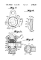
FIG. 1 is a sectional view in side elevation of the rotary plug valve of the present invention;
FIG. 2 is a view similar to FIG. 1 but showing the valve in an open condition;
FIG. 3 is a view similar to FIG. 1 but with the plug member removed;
FIG. 4 is a top plan view of the valve body of FIG. 3;
FIG. 5 is a view along lines 5--5 of FIG. 3; and
FIG. 6 is an enlarged detailed view of a sealing ridge on the internal wall of the valve body;
FIG. 7 is a view similar to FIG. 5 but showing another embodiment.
DETAILED DESCRIPTION OF THE INVENTION
Referring now to the drawings wherein like numerals designate corresponding parts through out the several views, there are shown in FIGS. 1 and 2, the valve 10 of the present invention. The valve 10 includes a valve body 12 which may be cast from a suitable metallic alloy or iron or brass or molded from plastic such polypropylene, the selection being being largely dependent on the environment in which the valve will be placed. As shown, the valve body is generally cylindrical in shape having a circumferential side wall 16 and an interior cylindrical wall 18 which defines a plug receiving chamber for receiving the generally cylindrical plug member 14. The body 12 is formed with a lateral inlet/outlet passage 20 and an axial inlet/outlet passage 22 which is internally threaded, as shown. Other connection methods such as external threads maybe used, of course.
The plug member 14 has a key member 24 having a locking tongue 25 (FIG. 2) formed on the upper portion thereof. The plug member 14 is formed with a hollow core 26 which may be partially filled with a resilient material 32 such as rubber or a synthetic elastomer. The hollow core 26 lies within a cylindrical wall 28 which is provided with aligned openings 29 for defining a through passage 40 which extends generally perpendicular to the longitudinal axis of the plug member 14. The cylindrical wall 28 is covered with a resilient material 30. In the manufacture of the plug member 14, the resilient cover 30 and the filler 32 may be integrally molded on the plug member 14 by conventional molding techniques. In one such process, the depth of the resilient cover 30 will be defined by a mold cavity and in the molding process, the hollow core 26 will be entirely filled. Core pins, 41 (FIG. 7) may be used during molding to form the passages 40 and 22 and 38. Alternately, a suitable machining of the passage 40 may be done such as by a drill or cutting punch. Other suitable techniques for providing the resilient cover 30 and filler 32 will be apparent to those skilled in this art. Preferably, the resilient cover is rubber although other synthetic resilient elastomers may be employed, if desired. The upper portion of the cylindrical wall 28 terminates adjacent a circumferential groove 34 which is provided for retaining an O-ring 36, as shown. Of course, complimentary shaped sealing rings may also be employed as will be apparent to those skilled in this art.
The end of the plug member 14 opposite the key 24 is opened to provide an inlet/outlet passage 38 which will be, in the illustrated embodiment, in communication with the inlet/outlet passage 22 of the valve body 12.
As shown in FIG. 1, the plug member 14 is in the closed position while in FIG. 2, the plug member 14 is in the open position whereby a fluid path through the valve 10 is established between passages 22, 38, 40 and 20.
By virtue of the improved sealing means provided by the present invention, the relative dimensions of the plug number 14 and the chamber defined by the interior wall 18 of the body 12 will be such that the plug member can be easily inserted axially into the body 12 to the position illustrated in FIGS. 1 and 2. A washer 46 may be provided on the external top portion of the plug member 14 about the key 24 and a snap ring 48 may be employed in combination with a retaining groove 50 to retain the plug member in its installed position. As will be evident to those skilled in this art, other means for retaining the plug 14 within the body 12 may be employed, if desired.
With reference now to FIG. 3, there is shown the plug receiving chamber 21 defined by the interior wall 18 of the plug valve body 12. As formed, raised surface means in the form of a plurality of ridges are provided in a selected pattern on the interior wall 18 to effect a fluid tight seal in cooperation with the resilient cover 30 of the plug member 14. Specifically, a first ridge 52 is formed about the periphery of the wall 18 above the passage 20 and a second identically shaped ridge 54 is provided below the outlet 20 about the entire circumference of the wall 18. By providing the ridges 52 and 54 about the entire internal circumference of the wall 18, fluid tight sealing will be achieved for any rotational position of the plug member 14. Indeed, in most applications, the sealing with respect to ridge 52 and the resilient cover 30 will be sufficient so that the O-ring 36 may be eliminated. In certain high pressure applications, however, it may be desirable to employ the O-ring 36 as a safety backup. Referring now to FIGS. 3 and 5, a pair of parallel extending third and fourth ridges, 56 and 58 respectively extend between the first and second ridges and are located on opposite sides of the passage 20 as clearly illustrated in FIG. 5. The third and fourth ridges extend parallel to the longitudinal axis of the body 12. A fifth and sixth pair of ridges 60 and 62 (FIG. 5) are located in mirror image to the third and fourth ridges 56 and 58. In such an arrangement, balanced rotation of the plug member 14 can be more easily effected. In addition, in the manufacture of the plug body 12, an end user may simply install a plug in the passage 22 and open a passage in axial alignment to passage 20 by drilling an opening between ridges 60 and 62 in the plug body 12.
As previously noted, the body 12 may be formed by conventional metal casting. With such an arrangement, the innermost flat surfaces 64 of each of the ridges should be ground or machined smooth by conventional deburring techniques. In addition, the points of intersection as at 66 between the first and second ridges and the four ridges which extend parallel to the longitudinal axis of the body 12 should also be ground smooth so that these intersections will be uninterrupted. The remainder of the interior of the body 12 need not be machined or ground and may be left rough thus resulting in significant savings in the manufacture of this valve body.
As shown in FIGS. 3 and 4, the chamber 21 has an internal flange 68 on which is formed a pair of blocks 42 and 43 which are diametrically disposed relative to the longitudinal axis of the body 12 and which protrude radially inwardly as shown in FIG. 4. The blocks 42 and 43 serve to stop tubing from entering when threaded in passages 22. With this arrangement, accurate alignment of the opening 40 in the plug member 14 relative to the passage 20 will be assured.
To assure smooth rotation of the plug member 14, particularly regarding relative movement between the resilient cover 30 and the third through sixth ridges, the side walls of the ridges as illustrated in FIG. 6 are sloped relative to the wall 18 with the angle of slope being between 20 and 45 degrees. Preferably, the angle of sloped is approximately 30 degrees. With the slope side walls 70 and 72 provided for each of the ridges, the resilient cover will be gradually compressed from its free molded diameter to the compressed state defined by the inside diameter of the metal ridges with the gradual transition from the uncompressed to the compressed condition minimizing wear or damage to the resilient cover 30.
As shown in FIG. 7, the body 12 may be formed with a tranverse opening 39 and associated connection. After molding, the piece 43 is discarded and when opening 39 is to be used, a plug is installed in 22.
From the foregoing, it will be apparent that a high integrity fluid seal will be achieved with the structure of the plug valve of the present invention and one which is characterized by high durability due to the relationship of the resilient cover and the sealing ridges.
Having described the invention, it will apparent to those skilled in the art that various modifications may be made thereto without departing from the spirit and scope of this invention as defined in the appended claims.

Claims (24)

What the claim is:
1. A rotary plug valve having a body including a wall defining a plug receiving chamber, a plug member including fluid passage therethrough and having a peripheral side wall portion having a selected diameter, said side wall portion having at least a resilient material to a selected depth, said wall of said body having openings therein disposed so that when said plug member is rotatably located in said chamber, said fluid passage will be alignable in flow communication with at least some of said openings, said wall further including raised metallic surface formed thereon extending from said wall into said chamber to a selected distance and located in a selected pattern relative to said openings so that, when said plug member is rotatably disposed in said plug receiving chamber, said metallic surface means will locally deform said resilient material and thereby sealingly engage sections of said resilient material of said plug member to substantially prevent leakage of fluid therebetween.
2. The invention as claimed in claim 1, wherein said plug member is substantially cylindrical in shape and has a longitudinal axis, along which said plug member wall extends, said fluid passage comprising a bore extending through said plug member substantially perpendicularly to said longitudinal axis.
3. The invention as claimed in claim 2, wherein said plug member further has end portions between which said side wall portions extend and includes a further fluid passage extending through one of said end portions and communicating with said bore.
4. The invention as claimed in claim 1, wherein said body has opposite ends which are open, one of which is of diameter sufficient to receive said plug member.
5. The invention as claimed in claim 1, wherein said body has opposite ends and one of said openings in said wall is located intermediate said opposite ends of said body, said plug member having a substantially cylindrical shape and having a longitudinal axis, said plug member further having end portions between which said side wall extends, said fluid passage comprising a bore extending through said plug member substantially perpendicularly to said longitudnal axis, said selected pattern of said raised surface means including a first circumferential ridge disposed on said wall on one side of said one opening and a second circumferential ridge disposed on said wall on the opposite side of said one opening.
6. The invention as claimed in claim 5, wherein said raised surface means further includes a third ridge extending between said first and second ridges and located on another side of said one opening and a fourth ridge extending between said first and second ridges and disposed on a side of said one opening opposite to said another side.
7. The invention as claimed in claim 6, wherein said raised surface means further includes fifth and sixth ridges both extending between said first and second ridges, said third, fourth, fifth and sixth ridges being spaced from one another about said wall of said body.
8. The invention as claimed in claim 7, wherein each of said third, fourth , fifth and sixth ridges have opposite ends which intersect, respectively, and first and second ridges.
9. The invention as claimed in claim 8, wherein the intersection of each of said ridges is a smooth and uninterrupted surface portion.
10. The invention as claimed in claim 6, wherein each said ridge is formed with side surfaces which slope outwardly from said wall of said body.
11. The invention as claimed in claim 10, wherein said side surfaces slope at an angle of between 20 and 45 degrees with respect to said wall of side body.
12. The invention as claimed in claim 11, wherein said angle of slope is approximately 30 degrees.
13. The invention as claimed in claim 5, wherein each said ridge is formed with side surface which slope outwardly from said wall of said body.
14. The invention as claimed in claim 13, wherein said side surfaces slope at an angle of between 20 and 45 degrees with respect to said wall of said body.
15. The invention as claimed in claim 14, wherein said angle of slope is approximately 30 degrees.
16. The invention as claimed in claim 5, wherein said ridges have inner surfaces which are ground smooth.
17. The invention as claimed in claim 1, wherein said resilient material is rubber.
18. The invention as claimed in claim 1, wherein said resilient material is molded on said side wall portion.
19. The invention as claimed in claim 1, wherein said body is cast metal and said raised surface means have inner surfaces which are formed smooth.
20. The invention as claimed in claim 1, wherein said selected depth of said resilient material on said side wall of said plug member and said selected distance to which said raised surface means extend from said wall of said body are such that said raised surface means compress said resilient material in the area of mutual engagement thereof.
21. The invention as claimed in claim 1, wherein said plug member has a hollow core which is at least partially filled with said resilient material.
22. The invention as claimed in claim 21, wherein said resilient material is molded rubber.
23. The invention as claimed in claim 1, wherein said plug member has opposite ends, one of said ends having an external groove formed circumferentially thereabout for receiving a sealing ring member.
24. The invention as claimed in claim 1, wherein said plug member has opposite ends, one of said ends carrying external key means.
US07/051,344 1987-05-19 1987-05-19 Plug valve havig interchangeable plug member Expired - Fee Related US4778152A (en)

Priority Applications (1)

Application Number Priority Date Filing Date Title
US07/051,344 US4778152A (en) 1987-05-19 1987-05-19 Plug valve havig interchangeable plug member

Applications Claiming Priority (1)

Application Number Priority Date Filing Date Title
US07/051,344 US4778152A (en) 1987-05-19 1987-05-19 Plug valve havig interchangeable plug member

Publications (1)

Publication Number Publication Date
US4778152A true US4778152A (en) 1988-10-18

Family

ID=21970731

Family Applications (1)

Application Number Title Priority Date Filing Date
US07/051,344 Expired - Fee Related US4778152A (en) 1987-05-19 1987-05-19 Plug valve havig interchangeable plug member

Country Status (1)

Country Link
US (1) US4778152A (en)

Cited By (17)

* Cited by examiner, † Cited by third party
Publication number Priority date Publication date Assignee Title
US5031876A (en) * 1987-06-30 1991-07-16 Siro, S.P.A. Cock with ball-shaped stopper
US6267353B1 (en) 1999-04-19 2001-07-31 Pbm, Inc. Self draining valve
WO2001061223A1 (en) * 2000-02-17 2001-08-23 A. Raymond & Cie Rotatable stopcock for a male coupling having a 90° offset connecting piece
EP1156243A1 (en) * 1999-11-30 2001-11-21 Denso Corporation Flow control valve
US6499721B2 (en) * 2001-02-12 2002-12-31 Michael Stolzman Bulk container valve
US20040021120A1 (en) * 2002-07-31 2004-02-05 Turnau Iii William F. Stop valve
WO2006119552A1 (en) * 2005-05-06 2006-11-16 Bolster Trading Pty Ltd Valve for a bladder
US20110052811A1 (en) * 2009-08-31 2011-03-03 Illinois Tool Works Inc. Metering system for simultaneously dispensing two different adhensives from a single metering device or applicator onto a common substrate
US20140228762A1 (en) * 2011-09-21 2014-08-14 Bayer Medical Care Inc. Continuous Multi-Fluid Pump Device, Drive and Actuating System and Method
US8833394B2 (en) 2010-08-13 2014-09-16 Ayrlett, Inc. Water supply valve
EP2918202A1 (en) * 2014-03-10 2015-09-16 Gebr. Echtermann GmbH & Co. KG Outlet port with connection device
US9573159B2 (en) 2009-08-31 2017-02-21 Illinois Tool Works, Inc. Metering system for simultaneously dispensing two different adhesives from a single metering device or applicator onto a common substrate
EP3183482A1 (en) * 2014-08-19 2017-06-28 Elysee Piping Systems Limited A mini valve for low pressure applications core with embedded sealing material and a double injection method for making same
US10443743B2 (en) 2017-11-14 2019-10-15 Brasscraft Manufacturing Company Rotary plug valve
US10507319B2 (en) 2015-01-09 2019-12-17 Bayer Healthcare Llc Multiple fluid delivery system with multi-use disposable set and features thereof
US20220146006A1 (en) * 2019-02-21 2022-05-12 Giacomini S.P.A. Valve for hydraulic control and balancing of fluid flow rate
RU211949U1 (en) * 2022-02-22 2022-06-29 Общество с ограниченной ответственностью "ТерминалСтройИнвест" CORK FAUCET

Citations (23)

* Cited by examiner, † Cited by third party
Publication number Priority date Publication date Assignee Title
DE2327C (en) * J. MALLINSON in Welwyn, Grafschaft Herts in England. Vertreter F. E. THODE & KNOOP in Berlin Innovations on steam and other taps, as well as valves
US2210335A (en) * 1939-01-25 1940-08-06 Mueller Co Valve
US2222626A (en) * 1939-01-25 1940-11-26 Mueller Co Valve
US2285222A (en) * 1940-10-31 1942-06-02 Mueller Co Valve
US2285221A (en) * 1940-06-07 1942-06-02 Mueller Co Valve
US2571925A (en) * 1945-04-13 1951-10-16 Mueller Co Valve
US3349799A (en) * 1965-04-20 1967-10-31 Mueller Co Rotary plug valve
US3350057A (en) * 1965-06-17 1967-10-31 Mueller Co Retainer ring and thrust washer arrangement for valves or the like
US3509903A (en) * 1968-07-17 1970-05-05 Mueller Co Lubricated rotary plug valve
US3554218A (en) * 1969-04-15 1971-01-12 Mueller Co Tamper-proof rotary plug valve
US3557832A (en) * 1964-12-10 1971-01-26 Mueller Co Ball valves
US3563512A (en) * 1969-12-08 1971-02-16 Mueller Co Tamperproof rotary valve assembly
US3684242A (en) * 1970-04-28 1972-08-15 Mueller Co Soft seated rotary valve
DE2145219A1 (en) * 1971-09-09 1973-03-15 Union Pump Co FILLED STOPcock
US3799500A (en) * 1972-07-06 1974-03-26 Mueller Co Rotary valve with anti-corrosion and torque controlling means
US3802661A (en) * 1972-07-06 1974-04-09 Mueller Co Rotary valve with anti-corrosion and torque controlling means
DE2414018A1 (en) * 1973-06-08 1975-01-02 Orbaiceta GAS BARRIER
US3882884A (en) * 1973-12-04 1975-05-13 Mueller Co Tamperproof open bottom stop assemblies
US3991975A (en) * 1975-07-08 1976-11-16 Mueller Co. Rotary plug valve with notched sealing ring groove
US4291859A (en) * 1979-12-10 1981-09-29 Aerojet-General Corporation Plug-type valve
US4410003A (en) * 1980-01-08 1983-10-18 Xomox Corporation Rotary plug valve
EP0178052A1 (en) * 1984-08-20 1986-04-16 The Babcock & Wilcox Company Valve core assembly for a shut-off/equalizing valve
US4628962A (en) * 1986-01-06 1986-12-16 United States Brass Corporation Tub-shower diverter valve

Patent Citations (23)

* Cited by examiner, † Cited by third party
Publication number Priority date Publication date Assignee Title
DE2327C (en) * J. MALLINSON in Welwyn, Grafschaft Herts in England. Vertreter F. E. THODE & KNOOP in Berlin Innovations on steam and other taps, as well as valves
US2210335A (en) * 1939-01-25 1940-08-06 Mueller Co Valve
US2222626A (en) * 1939-01-25 1940-11-26 Mueller Co Valve
US2285221A (en) * 1940-06-07 1942-06-02 Mueller Co Valve
US2285222A (en) * 1940-10-31 1942-06-02 Mueller Co Valve
US2571925A (en) * 1945-04-13 1951-10-16 Mueller Co Valve
US3557832A (en) * 1964-12-10 1971-01-26 Mueller Co Ball valves
US3349799A (en) * 1965-04-20 1967-10-31 Mueller Co Rotary plug valve
US3350057A (en) * 1965-06-17 1967-10-31 Mueller Co Retainer ring and thrust washer arrangement for valves or the like
US3509903A (en) * 1968-07-17 1970-05-05 Mueller Co Lubricated rotary plug valve
US3554218A (en) * 1969-04-15 1971-01-12 Mueller Co Tamper-proof rotary plug valve
US3563512A (en) * 1969-12-08 1971-02-16 Mueller Co Tamperproof rotary valve assembly
US3684242A (en) * 1970-04-28 1972-08-15 Mueller Co Soft seated rotary valve
DE2145219A1 (en) * 1971-09-09 1973-03-15 Union Pump Co FILLED STOPcock
US3802661A (en) * 1972-07-06 1974-04-09 Mueller Co Rotary valve with anti-corrosion and torque controlling means
US3799500A (en) * 1972-07-06 1974-03-26 Mueller Co Rotary valve with anti-corrosion and torque controlling means
DE2414018A1 (en) * 1973-06-08 1975-01-02 Orbaiceta GAS BARRIER
US3882884A (en) * 1973-12-04 1975-05-13 Mueller Co Tamperproof open bottom stop assemblies
US3991975A (en) * 1975-07-08 1976-11-16 Mueller Co. Rotary plug valve with notched sealing ring groove
US4291859A (en) * 1979-12-10 1981-09-29 Aerojet-General Corporation Plug-type valve
US4410003A (en) * 1980-01-08 1983-10-18 Xomox Corporation Rotary plug valve
EP0178052A1 (en) * 1984-08-20 1986-04-16 The Babcock & Wilcox Company Valve core assembly for a shut-off/equalizing valve
US4628962A (en) * 1986-01-06 1986-12-16 United States Brass Corporation Tub-shower diverter valve

Non-Patent Citations (2)

* Cited by examiner, † Cited by third party
Title
Bulletin H 1, Meter Valves, May 1977, Mueller Co. *
Bulletin H-1, Meter Valves, May 1977, Mueller Co.

Cited By (30)

* Cited by examiner, † Cited by third party
Publication number Priority date Publication date Assignee Title
US5031876A (en) * 1987-06-30 1991-07-16 Siro, S.P.A. Cock with ball-shaped stopper
US6267353B1 (en) 1999-04-19 2001-07-31 Pbm, Inc. Self draining valve
EP1156243A1 (en) * 1999-11-30 2001-11-21 Denso Corporation Flow control valve
EP1156243A4 (en) * 1999-11-30 2002-04-10 Denso Corp Flow control valve
CZ298055B6 (en) * 2000-02-17 2007-06-06 A. Raymond & Cie Rotatable stopcock for slide-in coupling with angularly displaced connecting neck
WO2001061223A1 (en) * 2000-02-17 2001-08-23 A. Raymond & Cie Rotatable stopcock for a male coupling having a 90° offset connecting piece
US6607179B2 (en) 2000-02-17 2003-08-19 A. Raymond & Cie. Rotatable stopcock for a male coupling having a 90° offset connecting piece
US6499721B2 (en) * 2001-02-12 2002-12-31 Michael Stolzman Bulk container valve
US7036793B2 (en) 2002-07-31 2006-05-02 Brass-Craft Manufacturing Company Stop valve
US20040021120A1 (en) * 2002-07-31 2004-02-05 Turnau Iii William F. Stop valve
WO2006119552A1 (en) * 2005-05-06 2006-11-16 Bolster Trading Pty Ltd Valve for a bladder
US20110052811A1 (en) * 2009-08-31 2011-03-03 Illinois Tool Works Inc. Metering system for simultaneously dispensing two different adhensives from a single metering device or applicator onto a common substrate
US9718081B2 (en) * 2009-08-31 2017-08-01 Illinois Tool Works Inc. Metering system for simultaneously dispensing two different adhesives from a single metering device or applicator onto a common substrate
US9573159B2 (en) 2009-08-31 2017-02-21 Illinois Tool Works, Inc. Metering system for simultaneously dispensing two different adhesives from a single metering device or applicator onto a common substrate
US8833394B2 (en) 2010-08-13 2014-09-16 Ayrlett, Inc. Water supply valve
US9599236B2 (en) 2010-08-13 2017-03-21 Ayrlett Llc Water supply valve
US20140228762A1 (en) * 2011-09-21 2014-08-14 Bayer Medical Care Inc. Continuous Multi-Fluid Pump Device, Drive and Actuating System and Method
JP2017185293A (en) * 2011-09-21 2017-10-12 バイエル・ヘルスケア・エルエルシーBayer HealthCare LLC Continuous multi-fluid pump device, drive and actuating system, and method
RU2624327C2 (en) * 2011-09-21 2017-07-03 БАЙЕР ХелсКер ЛЛСи Multifluid continuous pumping device, drive and actuating systems, and method
US9700672B2 (en) * 2011-09-21 2017-07-11 Bayer Healthcare Llc Continuous multi-fluid pump device, drive and actuating system and method
EP2918202A1 (en) * 2014-03-10 2015-09-16 Gebr. Echtermann GmbH & Co. KG Outlet port with connection device
US20170241554A1 (en) * 2014-08-19 2017-08-24 Elysee Piping Systems Limited A mini valve for low pressure applications core with embedded sealing material and a double injection method for making same
EP3183482A1 (en) * 2014-08-19 2017-06-28 Elysee Piping Systems Limited A mini valve for low pressure applications core with embedded sealing material and a double injection method for making same
EP3183482B1 (en) * 2014-08-19 2022-02-23 Elysee Piping Systems Limited A mini valve for low pressure applications core with embedded sealing material and a double injection method for making same
US10507319B2 (en) 2015-01-09 2019-12-17 Bayer Healthcare Llc Multiple fluid delivery system with multi-use disposable set and features thereof
US11491318B2 (en) 2015-01-09 2022-11-08 Bayer Healthcare Llc Multiple fluid delivery system with multi-use disposable set and features thereof
US10443743B2 (en) 2017-11-14 2019-10-15 Brasscraft Manufacturing Company Rotary plug valve
US20220146006A1 (en) * 2019-02-21 2022-05-12 Giacomini S.P.A. Valve for hydraulic control and balancing of fluid flow rate
US11867302B2 (en) * 2019-02-21 2024-01-09 Giacomini S.P.A. Valve for hydraulic control and balancing of fluid flow rate
RU211949U1 (en) * 2022-02-22 2022-06-29 Общество с ограниченной ответственностью "ТерминалСтройИнвест" CORK FAUCET

Similar Documents

Publication Publication Date Title
US4778152A (en) Plug valve havig interchangeable plug member
US3768774A (en) Gate valve with pressure actuated plug seat
US4572239A (en) High pressure ball valve
US3778028A (en) Lined butterfly valve
US4113268A (en) Extended temperature range valve seal
US2740423A (en) Disc valve
US4511120A (en) Plastic service valve
US3133723A (en) Gas valves
US4479513A (en) High pressure ball valve
US3346005A (en) Lined butterfly valves
EP0520997B1 (en) A ball valve
US4257575A (en) Rotary ball valve having seating rings
EP0178052B1 (en) Valve core assembly for a shut-off/equalizing valve
US5234193A (en) Rotary plug valve with seat seal
US20050104026A1 (en) Ball valve with a single piece ball-stem and an integrated actuator mounting flange
US3069129A (en) Valve construction having fluid pressure and spring bias seals
US3712584A (en) Valve and method of making same
US4180542A (en) Methods for making molded plug and plug valve
US3951380A (en) Demountable valve
US4542878A (en) Ball valve
EP0144651B1 (en) Ball valve and method of manufacturing the same
US4988077A (en) Reinforced plastic valve
US3397861A (en) Valve seat with backing
US5154396A (en) Reinforced plastic valve
GB1571875A (en) Extendend temperature range valve seal

Legal Events

Date Code Title Description
AS Assignment

Owner name: MUELLER CO., 500 WEST ELDORADO ST., DECATUR, ILL.

Free format text: ASSIGNMENT OF ASSIGNORS INTEREST.;ASSIGNOR:LOGMAN, TIMOTHY M.;REEL/FRAME:004741/0203

Effective date: 19870716

Owner name: MUELLER CO.,ILLINOIS

Free format text: ASSIGNMENT OF ASSIGNORS INTEREST;ASSIGNOR:LOGMAN, TIMOTHY M.;REEL/FRAME:004741/0203

Effective date: 19870716

REMI Maintenance fee reminder mailed
LAPS Lapse for failure to pay maintenance fees
FP Lapsed due to failure to pay maintenance fee

Effective date: 19921018

STCH Information on status: patent discontinuation

Free format text: PATENT EXPIRED DUE TO NONPAYMENT OF MAINTENANCE FEES UNDER 37 CFR 1.362