US4783711A - Magnetoresistive sensor having magnetic shields of ferrite - Google Patents

Magnetoresistive sensor having magnetic shields of ferrite Download PDF

Info

Publication number
US4783711A
US4783711A US06/879,567 US87956786A US4783711A US 4783711 A US4783711 A US 4783711A US 87956786 A US87956786 A US 87956786A US 4783711 A US4783711 A US 4783711A
Authority
US
United States
Prior art keywords
ferrite
magnetoresistive sensor
ferromagnetic metal
magnetoresistive
metal film
Prior art date
Legal status (The legal status is an assumption and is not a legal conclusion. Google has not performed a legal analysis and makes no representation as to the accuracy of the status listed.)
Expired - Fee Related
Application number
US06/879,567
Inventor
Masahiro Kitada
Hideo Tanabe
Noboru Shimizu
Hitoshi Nakamura
Kazuhiro Momata
Shigeyoshi Kato
Tooru Takeura
Tetsuo Kobayashi
Current Assignee (The listed assignees may be inaccurate. Google has not performed a legal analysis and makes no representation or warranty as to the accuracy of the list.)
Hitachi Ltd
Original Assignee
Hitachi Ltd
Priority date (The priority date is an assumption and is not a legal conclusion. Google has not performed a legal analysis and makes no representation as to the accuracy of the date listed.)
Filing date
Publication date
Priority claimed from JP60152213A external-priority patent/JPS6214318A/en
Priority claimed from JP60247020A external-priority patent/JPS62107422A/en
Application filed by Hitachi Ltd filed Critical Hitachi Ltd
Assigned to HITACHI, LTD., A CORP. OF JAPAN reassignment HITACHI, LTD., A CORP. OF JAPAN ASSIGNMENT OF ASSIGNORS INTEREST. Assignors: KATO, SHIGEYOSHI, KITADA, MASAHIRO, KOBAYASHI, TETSUO, MOMATA, KAZUHIRO, NAKAMURA, HITOSHI, SHIMIZU, NOBORU, TAKEURA, TOORU, TANABE, HIDEO
Application granted granted Critical
Publication of US4783711A publication Critical patent/US4783711A/en
Anticipated expiration legal-status Critical
Expired - Fee Related legal-status Critical Current

Links

Images

Classifications

    • GPHYSICS
    • G11INFORMATION STORAGE
    • G11BINFORMATION STORAGE BASED ON RELATIVE MOVEMENT BETWEEN RECORD CARRIER AND TRANSDUCER
    • G11B5/00Recording by magnetisation or demagnetisation of a record carrier; Reproducing by magnetic means; Record carriers therefor
    • G11B5/127Structure or manufacture of heads, e.g. inductive
    • BPERFORMING OPERATIONS; TRANSPORTING
    • B82NANOTECHNOLOGY
    • B82YSPECIFIC USES OR APPLICATIONS OF NANOSTRUCTURES; MEASUREMENT OR ANALYSIS OF NANOSTRUCTURES; MANUFACTURE OR TREATMENT OF NANOSTRUCTURES
    • B82Y25/00Nanomagnetism, e.g. magnetoimpedance, anisotropic magnetoresistance, giant magnetoresistance or tunneling magnetoresistance
    • GPHYSICS
    • G01MEASURING; TESTING
    • G01RMEASURING ELECTRIC VARIABLES; MEASURING MAGNETIC VARIABLES
    • G01R33/00Arrangements or instruments for measuring magnetic variables
    • G01R33/02Measuring direction or magnitude of magnetic fields or magnetic flux
    • G01R33/06Measuring direction or magnitude of magnetic fields or magnetic flux using galvano-magnetic devices
    • G01R33/09Magnetoresistive devices
    • G01R33/093Magnetoresistive devices using multilayer structures, e.g. giant magnetoresistance sensors
    • GPHYSICS
    • G11INFORMATION STORAGE
    • G11BINFORMATION STORAGE BASED ON RELATIVE MOVEMENT BETWEEN RECORD CARRIER AND TRANSDUCER
    • G11B5/00Recording by magnetisation or demagnetisation of a record carrier; Reproducing by magnetic means; Record carriers therefor
    • G11B5/127Structure or manufacture of heads, e.g. inductive
    • G11B5/33Structure or manufacture of flux-sensitive heads, i.e. for reproduction only; Combination of such heads with means for recording or erasing only
    • G11B5/39Structure or manufacture of flux-sensitive heads, i.e. for reproduction only; Combination of such heads with means for recording or erasing only using magneto-resistive devices or effects
    • G11B5/3903Structure or manufacture of flux-sensitive heads, i.e. for reproduction only; Combination of such heads with means for recording or erasing only using magneto-resistive devices or effects using magnetic thin film layers or their effects, the films being part of integrated structures

Definitions

  • the present invention relates to a magnetic sensor, and particularly it relates to a magnetoresistive sensor such as a reproducing magnetic head which uses a magnetoresistive element suited for a magnetic recording system such as a magnetic disk system or a magnetic tape system.
  • a magnetoresistive film is formed on high permeability magnetic ferrite (Ni-Zn or Mn-Zn ferrite) with an insulating film of SiO 2 , Al 2 O 3 or the like interposed between them.
  • the magnetoresistive film generates a very large quantity of heat, since high current of 10 5 to 10 6 A/cm 2 or above is applied thereon.
  • the high permeability magnetic ferrite has a very low heat conductivity. Therefore the temperature of the element is increased by the heat and this causes the deterioration of characteristics.
  • no consideration has been given heretofore to rapidly releasing a high heat caused thereby and keeping the element at low temperature.
  • the aforesaid ferrite which is used as a magnetic shield, is bulky ferrite which has a saturation flux density of 0.5 T at the highest and a permeability of about 200 to 300 at the most at 10 MHz, and thus flux from a magnetic recording medium scatters into the whole ferrite at low density. Therefore, the flux density in the vicinity of a magnetic gap is low. In this connection, no consideration has been given to making a reproduced waveform from the magnetoresistive film sharp, though the waveform therefrom is broad.
  • An object of the present invention is to furnish a magnetic sensor such as a magnetoresistive effect type reproducing head which enables the reduction in temperature rise in a magnetoresistive effect element unit and has a high output and a long life.
  • a magnetic sensor such as a ferrite shield type magnetoresistive effect head which reproduces a sharp waveform.
  • the magnetoresistive sensor of the present invention is constructed in such a manner that a magnetoresistive effect element having a magnetoresistive film is held between two magnetic shields formed of high permeability magnetic ferrite, with an insulating layer interposed between the element and the shield, and a ferromagnetic metal film is formed adherently to said ferrite between at least one of the magnetic shields formed of the ferrite and said insulating layer.
  • the above-stated magnetoresistive sensor of the present invention enables the rapid dissipation of a heat generated from the magnetoresistive film without the deterioration of the characteristics of the magnetic shields, thus preventing decrease of the output and reduction of the life of the element which would otherwise be caused by a rise in temperature of the magnetoresistive film.
  • the ferromagnetic metal film has generally a remarkably higher thermal conductivity than that of the high permeability magnetic ferrite.
  • the aforesaid ferromagnetic metal film may be formed of any metal material, including, for instance, an Ni-Fe alloy such as Ni-19 wt% Fe alloy (so-called permalloy), Fe-Si alloy, Co-Ni alloy, Fe-Si-Al alloy (so-called sendust) or a high permeability amorphous alloy such as Co-Mo-Zr amorphous alloy, for instance, which is formed by adding flass former element(s) such as Si, Ge, B, Ti, Zr, Mo, Nb, W and Ta to Co, Fe and/or Ni, the main components, on condition that the material has a permeability and/or a saturation flux density higher than or approximately equal to those of the high permeability magnetic ferrite.
  • an Ni-Fe alloy such as Ni-19 wt% Fe alloy (so-called permalloy), Fe-Si alloy, Co-Ni alloy, Fe-Si-Al alloy (so-called sendust
  • FIG. 1 is a sectional view showing a conventional magnetoresistive sensor
  • FIG. 2 is a sectional view showing a magnetoresistive sensor in one embodiment of the present invention
  • FIG. 3a is an illustration of a reproduced waveform in the conventional magnetoresistive sensor
  • FIG. 3b is an illustration of a reproduced waveform in the magnetoresistive sensor in one embodiment of the present invention.
  • FIG. 4 is a graph showing the effect of the thickness of a ferromagnetic metal film adhering to ferrite on the output of the magnetoresistive sensor in one embodiment of the present invention and on the half-width of the reproduced waveform therein.
  • FIG. 1 the sectional structure of a conventional ferrite shield type magnetoresistive effect head is shown in FIG. 1.
  • numerals 1 and 2 denote high permeability magnetic ferrite such as nickel-zinc (Ni-Zn) ferrite, 3 an insulating layer of Al 2 O 3 , SiO 2 or the like, 4 an insulating layer of glass or an organic substance, 5 a magnetoresistive film, and 6 a conductive film for magnetic bias which acts also as a conductive film for a current terminal.
  • high permeability magnetic ferrite such as nickel-zinc (Ni-Zn) ferrite
  • 3 an insulating layer of Al 2 O 3 , SiO 2 or the like
  • 4 an insulating layer of glass or an organic substance
  • 5 magnetoresistive film
  • 6 a conductive film for magnetic bias which acts also as a conductive film for a current terminal.
  • the magnetoresistive sensor of the present invention is constructed, for instance, by forming a ferromagnetic metal film between the ferrite 1 and the insulating layer 3 and/or between the ferrite 2 and the insulating layer 4 in the magnetoresistive effect head of FIG. 1 in such a manner that it is adherent to each ferrite.
  • FIG. 2 is a sectional view of a magnetoresistive sensor in the present embodiment, showing a ferrite/metal composite shield type magnetoresistive effect head.
  • numerals 7 and 8 denote high permeability magnetic ferrite such as Ni-Zn ferrite, 9 a ferromagnetic crystalline or amorphous metal film, 10 an insulating layer of Al 2 O 3 or the like, 11 a magnetoresistive film, 12 a magnetic biasing conductive film which is formed of a conductor of Mo, Ti, Au or the like and acts also as a current terminal, 13 an insulating film formed of a glass or an organic substance, and 14 the same ferromagnetic metal film as the above 9.
  • high permeability magnetic ferrite such as Ni-Zn ferrite
  • 9 a ferromagnetic crystalline or amorphous metal film
  • 10 an insulating layer of Al 2 O 3 or the like
  • 11 a magnetoresistive film
  • 12 a magnetic biasing conductive film which is
  • the aforesaid high permeability magnetic ferrite 7 and 8 have a shield effect, and Ni-Zn ferrite 2 mm thick is used therefor in the present embodiment.
  • Ni-Zn ferrite 2 mm thick is used therefor in the present embodiment.
  • a Ni-19 wt% Fe alloy (permalloy) of thickness 0.1 to 3 ⁇ m is used for the ferromagnetic metal films 9 and 14.
  • a Ni-19 wt% Fe alloy permalloy
  • For the magnetoresistive film 11 a Ni-19 wt% Fe alloy is used.
  • the above-stated magnetoresistive effect head in the present embodiment is manufactured in such a way that the aforesaid layers and films are formed on the high permeability magnetic ferrite 7 by such a well-known thin film forming technique as sputtering or vacuum evaporation and further the high permeability magnetic ferrite 8 is connected on the layered structure by using an adhesive.
  • a magnetoresistive effect element On a magnetoresistive effect element, generally, current of 5 ⁇ 10 5 to 5 ⁇ 10 6 A/cm 2 is applied, and most of the heat generated thereby is dissipated by the heat conduction to the surrounding solid parts. If the magnetic metal substances denoted by the numerals 9 and 14 in FIG. 2 are not present, the heat is dissipated only through oxide parts whose thermal conductivity is low. Therefore a rise in temperature in the parts of the magnetoresistive film and the magnetic biasing metal film is very great, which causes the thermal deterioration of the magnetoresistive element. For instance, the temperature of the element is raised to about 75° C. by the electric current of 5 ⁇ 10 5 A/cm 2 and to about 150° C.
  • the ferromagnetic metal film is formed on the inner surface of the ferrite part as is the case with the present invention, on the contrary, the dissipation of heat in this part is very excellent, and thus the rise in temperature of the element is held down effectively.
  • the temperature of the element is about 25° C. in the case of 5 ⁇ 10 5 A/cm 2 , and about 80° C.
  • the output of the magnetoresistive film lowers linearly with a rise in temperature, it increases by two to three times in the case of a high current density operation by the hold-down of the rise in temperature.
  • the breakdown of the element i.e. the reduction of life of the element, due to electromigration caused by applying electric current on the element is accelerated exponentially in relation to temperature by thermal activation. Therefore, the life of the element is elongated five to ten times as much by the hold-down of the rise in temperature.
  • the ferromagnetic metal films 9 and 14 may be formed also of a ferromagnetic amorphous alloy other than a crystalline alloy such as the Ni-Fe alloy used in the present embodiment.
  • An amorphous metal has a higher hardness in general than a crystalline metal. Therefore the employment thereof for the head has an advantage that the wear of the head in the plane facing a magnetic recording medium is little.
  • the formation of only either one of the ferromagnetic metal films 9 and 14 shown in FIG. 2 is sufficient for the dissipation of heat.
  • the ferromagnetic metal films 9 and 14 show a remarkable effect of heat dissipation when their thickness is larger than about 0.1 ⁇ m.
  • the effect of heat dissipation shown by the ferromagnetic metal films is enhanced as the thickness thereof is increased.
  • the thickness is properly 2 to 3 ⁇ m at most when the rubbing of the head on a magnetic recording medium, the wear thereof, exfoliation of the thin film caused by an internal stress and further the fall of an output, which will be described later, etc. are considered.
  • the present invention has also such advantage that any one of systems of impressing a magnetic bias on the magnetoresistive film is applicable thereto.
  • the saturation flux density Bs permalloy is 1 T
  • that of an amorphous magnetic substance is 0.7 to 0.9 T
  • that of sendust is 1 to 1.3 T.
  • the saturation flux density Bs of all of these materials is 1.5 to 2.5 times larger than the value 0.5 T of the ferrite.
  • permalloy has a permeability of 2000, for instance, compared with 200 to 300 of the ferrite.
  • FIG. 3a shows a reproduced waveform 15 obtained from a conventional magnetoresistive effect head
  • FIG. 3b a reproduced waveform 16 obtained from a magnetoresistive effect head which is prepared by using an Ni-19 wt% Fe alloy (permalloy) of thickness 0.5 ⁇ m for the ferromagnetic metal films 9 and 14 in the present embodiment.
  • the construction of the present invention has a very remarkably effect on the reproduced waveform of the magnetoresistive effect head.
  • FIG. 4 shows the relationships between the ratio V 1 /V 0 (curve 17) of the output V 1 of the magnetoresistive effect head of the present embodiment of the output V 0 of the conventional magnetoresistive effect head, and the ratio W 1 /W 0 (curve 18) of the half-width W 1 of the reproduced waveform of the head of the present embodiment shown in FIG. 3b to the half-width W 0 of the reproduced waveform of the conventional head shown in FIG. 3a, on one side, and the thickness of the ferromagnetic metal films 9 and 14, on the other, in the form of curves 17 and 18 respectively.
  • FIG. 4 quantitatively shows the effect of an improvement in the output which is produced by making the output waveform sharp in the present invention.
  • the thickness of the ferromagnetic metal films 9 and 14 reaches 0.2 to 0.3 ⁇ m, and the effect becomes constant substantially when the thickness exceeds 0.8 ⁇ m.
  • the thickness of the ferromagnetic metal film should be 0.2 to 3 ⁇ m when it is desired not only to hold down the rise in temperature of the element, but also to make the reproduced waveform sharp.
  • the present invention enables the rapid dissipation of the heat of the magnetoresistive film of the magnetoresistive sensor, as described above, it has a remarkable effect of the prevention of the deterioration of the characteristics of the element, and also an effect of improving the characteristics of the element effectively. Furthermore, since it can make a reproduced signal waveform sharp and thus improve the output, the present invention can make a high density magnetic recording head reproduce waveforms of a higher frequency than usual, producing also an effect of facilitating an electric processing of signals.

Abstract

In a magnetoresistive sensor having a magnetoresistive effect element which is held between two sheets of high permeability magnetic ferrite with insulating layers interposed between them, a ferromagnetic metal film is provided adherently to the high permeability magnetic ferrite between the ferrite and the insulating layer, a rise in temperature of the magnetoresistive effect element thereby being held down and a reproduced waveform being made sharp, and thus the characteristics of the element being improved with the life thereof prolonged.

Description

BACKGROUND OF THE INVENTION
The present invention relates to a magnetic sensor, and particularly it relates to a magnetoresistive sensor such as a reproducing magnetic head which uses a magnetoresistive element suited for a magnetic recording system such as a magnetic disk system or a magnetic tape system.
In a conventional magnetoresistive sensor, as disclosed in the Specification of the U.S. Pat. No. 3,940,797, a magnetoresistive film is formed on high permeability magnetic ferrite (Ni-Zn or Mn-Zn ferrite) with an insulating film of SiO2, Al2 O3 or the like interposed between them. The magnetoresistive film generates a very large quantity of heat, since high current of 105 to 106 A/cm2 or above is applied thereon. The high permeability magnetic ferrite has a very low heat conductivity. Therefore the temperature of the element is increased by the heat and this causes the deterioration of characteristics. However, no consideration has been given heretofore to rapidly releasing a high heat caused thereby and keeping the element at low temperature.
Moreover, the aforesaid ferrite, which is used as a magnetic shield, is bulky ferrite which has a saturation flux density of 0.5 T at the highest and a permeability of about 200 to 300 at the most at 10 MHz, and thus flux from a magnetic recording medium scatters into the whole ferrite at low density. Therefore, the flux density in the vicinity of a magnetic gap is low. In this connection, no consideration has been given to making a reproduced waveform from the magnetoresistive film sharp, though the waveform therefrom is broad.
SUMMARY OF THE INVENTION
An object of the present invention is to furnish a magnetic sensor such as a magnetoresistive effect type reproducing head which enables the reduction in temperature rise in a magnetoresistive effect element unit and has a high output and a long life. Another object of the present invention is to furnish a magnetic sensor such as a ferrite shield type magnetoresistive effect head which reproduces a sharp waveform.
In order to attain the above-stated objects, the magnetoresistive sensor of the present invention is constructed in such a manner that a magnetoresistive effect element having a magnetoresistive film is held between two magnetic shields formed of high permeability magnetic ferrite, with an insulating layer interposed between the element and the shield, and a ferromagnetic metal film is formed adherently to said ferrite between at least one of the magnetic shields formed of the ferrite and said insulating layer.
By forming on the high permeability magnetic ferrite said ferromagnetic metal film having a permeability and a saturation flux density at least similar to those of said ferrite, the above-stated magnetoresistive sensor of the present invention enables the rapid dissipation of a heat generated from the magnetoresistive film without the deterioration of the characteristics of the magnetic shields, thus preventing decrease of the output and reduction of the life of the element which would otherwise be caused by a rise in temperature of the magnetoresistive film. This is enabled because the ferromagnetic metal film has generally a remarkably higher thermal conductivity than that of the high permeability magnetic ferrite. In this case an especially excellent action of heat dissipation can be attained with little deterioration due to wear and exfoliation, by making said film 0.1 to 3 μm thick. Moreover, when the permeability and/or the saturation flux density of this ferromagnetic metal film are higher than those of the aforesaid ferrite, the flux density of the shield side becomes high when the flux permeates into the film, and thereby an output waveform can be made so sharp that an output can be improved. In the case when this effect is to be utilized, it is preferable to make the ferromagnetic metal film 0.2 to 3 μm thick, and a more excellent result can be obtained especially when the thickness is made to be 0.8 to 3 μm.
The aforesaid ferromagnetic metal film may be formed of any metal material, including, for instance, an Ni-Fe alloy such as Ni-19 wt% Fe alloy (so-called permalloy), Fe-Si alloy, Co-Ni alloy, Fe-Si-Al alloy (so-called sendust) or a high permeability amorphous alloy such as Co-Mo-Zr amorphous alloy, for instance, which is formed by adding flass former element(s) such as Si, Ge, B, Ti, Zr, Mo, Nb, W and Ta to Co, Fe and/or Ni, the main components, on condition that the material has a permeability and/or a saturation flux density higher than or approximately equal to those of the high permeability magnetic ferrite.
BRIEF DESCRIPTION OF THE DRAWINGS
FIG. 1 is a sectional view showing a conventional magnetoresistive sensor;
FIG. 2 is a sectional view showing a magnetoresistive sensor in one embodiment of the present invention;
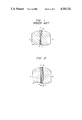
FIG. 3a is an illustration of a reproduced waveform in the conventional magnetoresistive sensor;
FIG. 3b is an illustration of a reproduced waveform in the magnetoresistive sensor in one embodiment of the present invention; and
FIG. 4 is a graph showing the effect of the thickness of a ferromagnetic metal film adhering to ferrite on the output of the magnetoresistive sensor in one embodiment of the present invention and on the half-width of the reproduced waveform therein.
DESCRIPTION OF THE PREFERRED EMBODIMENTS
First, the sectional structure of a conventional ferrite shield type magnetoresistive effect head is shown in FIG. 1. In this figure, numerals 1 and 2 denote high permeability magnetic ferrite such as nickel-zinc (Ni-Zn) ferrite, 3 an insulating layer of Al2 O3, SiO2 or the like, 4 an insulating layer of glass or an organic substance, 5 a magnetoresistive film, and 6 a conductive film for magnetic bias which acts also as a conductive film for a current terminal.
The magnetoresistive sensor of the present invention is constructed, for instance, by forming a ferromagnetic metal film between the ferrite 1 and the insulating layer 3 and/or between the ferrite 2 and the insulating layer 4 in the magnetoresistive effect head of FIG. 1 in such a manner that it is adherent to each ferrite.
Embodiment 1
FIG. 2 is a sectional view of a magnetoresistive sensor in the present embodiment, showing a ferrite/metal composite shield type magnetoresistive effect head. In FIG. 2, numerals 7 and 8 denote high permeability magnetic ferrite such as Ni-Zn ferrite, 9 a ferromagnetic crystalline or amorphous metal film, 10 an insulating layer of Al2 O3 or the like, 11 a magnetoresistive film, 12 a magnetic biasing conductive film which is formed of a conductor of Mo, Ti, Au or the like and acts also as a current terminal, 13 an insulating film formed of a glass or an organic substance, and 14 the same ferromagnetic metal film as the above 9. The aforesaid high permeability magnetic ferrite 7 and 8 have a shield effect, and Ni-Zn ferrite 2 mm thick is used therefor in the present embodiment. For the ferromagnetic metal films 9 and 14, a Ni-19 wt% Fe alloy (permalloy) of thickness 0.1 to 3 μm is used. For the magnetoresistive film 11, a Ni-19 wt% Fe alloy is used. The above-stated magnetoresistive effect head in the present embodiment is manufactured in such a way that the aforesaid layers and films are formed on the high permeability magnetic ferrite 7 by such a well-known thin film forming technique as sputtering or vacuum evaporation and further the high permeability magnetic ferrite 8 is connected on the layered structure by using an adhesive.
On a magnetoresistive effect element, generally, current of 5×10⁵ to 5×10⁶ A/cm2 is applied, and most of the heat generated thereby is dissipated by the heat conduction to the surrounding solid parts. If the magnetic metal substances denoted by the numerals 9 and 14 in FIG. 2 are not present, the heat is dissipated only through oxide parts whose thermal conductivity is low. Therefore a rise in temperature in the parts of the magnetoresistive film and the magnetic biasing metal film is very great, which causes the thermal deterioration of the magnetoresistive element. For instance, the temperature of the element is raised to about 75° C. by the electric current of 5×10⁵ A/cm2 and to about 150° C. by the electric current of 5×10⁶ A/cm2. Although this rise in temperature is varied locally according to the shape and location of the element, of course, it differs little from the aforesaid values on an average. When the ferromagnetic metal film is formed on the inner surface of the ferrite part as is the case with the present invention, on the contrary, the dissipation of heat in this part is very excellent, and thus the rise in temperature of the element is held down effectively. When the Ni-19 wt% Fe film of thickness 0.5 μm is used as the ferromagnetic metal film, for instance, the temperature of the element is about 25° C. in the case of 5×10⁵ A/cm2, and about 80° C. even in the case of 5×10⁶ A/cm2. Since the output of the magnetoresistive film lowers linearly with a rise in temperature, it increases by two to three times in the case of a high current density operation by the hold-down of the rise in temperature. The breakdown of the element, i.e. the reduction of life of the element, due to electromigration caused by applying electric current on the element is accelerated exponentially in relation to temperature by thermal activation. Therefore, the life of the element is elongated five to ten times as much by the hold-down of the rise in temperature.
The ferromagnetic metal films 9 and 14 may be formed also of a ferromagnetic amorphous alloy other than a crystalline alloy such as the Ni-Fe alloy used in the present embodiment. An amorphous metal has a higher hardness in general than a crystalline metal. Therefore the employment thereof for the head has an advantage that the wear of the head in the plane facing a magnetic recording medium is little.
When a working current density is relatively small, the formation of only either one of the ferromagnetic metal films 9 and 14 shown in FIG. 2 is sufficient for the dissipation of heat. The ferromagnetic metal films 9 and 14 show a remarkable effect of heat dissipation when their thickness is larger than about 0.1 μm. The effect of heat dissipation shown by the ferromagnetic metal films is enhanced as the thickness thereof is increased. However, the thickness is properly 2 to 3 μm at most when the rubbing of the head on a magnetic recording medium, the wear thereof, exfoliation of the thin film caused by an internal stress and further the fall of an output, which will be described later, etc. are considered.
In addition, the present invention has also such advantage that any one of systems of impressing a magnetic bias on the magnetoresistive film is applicable thereto.
The foregoing is a description on the case in which the hold-down of the rise in temperature of the element is intended. When it is intended to make an output waveform sharp so as to improve an output as well as to hold down said rise in temperature of the element, it is necessary to use a material higher in saturation flux density Bs and/or permeability μ than the high permeability magnetic ferrite for preparing the ferromagnetic metal films 9 and 14. For instance, the saturation flux density Bs permalloy is 1 T, that of an amorphous magnetic substance is 0.7 to 0.9 T, and that of sendust is 1 to 1.3 T. The saturation flux density Bs of all of these materials is 1.5 to 2.5 times larger than the value 0.5 T of the ferrite. As for the permeability in a frequency of 10 MHz, permalloy has a permeability of 2000, for instance, compared with 200 to 300 of the ferrite.
FIG. 3a shows a reproduced waveform 15 obtained from a conventional magnetoresistive effect head, and FIG. 3b a reproduced waveform 16 obtained from a magnetoresistive effect head which is prepared by using an Ni-19 wt% Fe alloy (permalloy) of thickness 0.5 μm for the ferromagnetic metal films 9 and 14 in the present embodiment. As is apparent from FIGS. 3a and 3b, the construction of the present invention has a very remarkably effect on the reproduced waveform of the magnetoresistive effect head.
FIG. 4 shows the relationships between the ratio V1 /V0 (curve 17) of the output V1 of the magnetoresistive effect head of the present embodiment of the output V0 of the conventional magnetoresistive effect head, and the ratio W1 /W0 (curve 18) of the half-width W1 of the reproduced waveform of the head of the present embodiment shown in FIG. 3b to the half-width W0 of the reproduced waveform of the conventional head shown in FIG. 3a, on one side, and the thickness of the ferromagnetic metal films 9 and 14, on the other, in the form of curves 17 and 18 respectively. FIG. 4 quantitatively shows the effect of an improvement in the output which is produced by making the output waveform sharp in the present invention. With respect to both the output and the waveform, a remarkable effect can be perceived when the thickness of the ferromagnetic metal films 9 and 14 reaches 0.2 to 0.3 μm, and the effect becomes constant substantially when the thickness exceeds 0.8 μm. When the thickness is over 2 to 3 μm, however, the effect tends to lessen a little. Therefore, the thickness of the ferromagnetic metal film should be 0.2 to 3 μm when it is desired not only to hold down the rise in temperature of the element, but also to make the reproduced waveform sharp.
Since the present invention enables the rapid dissipation of the heat of the magnetoresistive film of the magnetoresistive sensor, as described above, it has a remarkable effect of the prevention of the deterioration of the characteristics of the element, and also an effect of improving the characteristics of the element effectively. Furthermore, since it can make a reproduced signal waveform sharp and thus improve the output, the present invention can make a high density magnetic recording head reproduce waveforms of a higher frequency than usual, producing also an effect of facilitating an electric processing of signals.

Claims (14)

What is claimed is:
1. In a magnetoresistive sensor in which a magnetoresistive effect element having a magnetoresistive film is held between two magnetic shields formed of high permeability magnetic ferrite, with insulating layers interposed between the element and the shields, a magnetoresistive sensor characterized in that, between each of the magnetic shields formed of said high permeability magnetic ferrite and said insulating layer, a ferromagnetic metal film having a higher thermal conductivity than that of said high permeability magnetic ferrite is formed adherently to said ferrite.
2. A magnetoresistive sensor according to claim 1, characterized in that the permeability and the saturation flux density of said ferromagnetic metal film are substantially equal to or higher than those of said high permeability magnetic ferrite.
3. A magnetoresistive sensor according to claim 2, characterized in that the permeability and/or the saturation flux density of said ferromagnetic metal film are higher than those of said high permeability magnetic ferrite.
4. A magnetoresistive sensor according to claim 2, characterized in that the thickness of said ferromagnetic metal film is 0.1 to 3 μm.
5. A magnetoresistive sensor according to claim 3, characterized in that the thickness of said ferromagnetic metal film is 0.8 to 3 μm.
6. A magnetoresistive sensor according to claim 3, characterized in that the thickness of said ferromagnetic metal film is 0.2 to 3 μm.
7. A magnetoresistive sensor according to claim 1, characterized in that the thickness of said ferromagnetic metal film is 0.1 to 3 μm.
8. A magnetoresistive sensor according to claim 1, characterized in that said ferromagnetic metal film is a magnetic crystalline material.
9. A magnetoresistive sensor according to claim 1, characterized in that said ferromagnetic metal film is a magnetic amorphous material.
10. A magnetoresistive sensor according to claim 9, wherein said magnetic amorphous material is a Co-Mo-Zr amorphous alloy.
11. A magnetoresistive sensor according to claim 1, wherein said high permeability magnetic ferrite is a material selected from the group consisting of Ni-Zn ferrite and Mn-Zn ferrite.
12. A magnetoresistive sensor according to claim 1, wherein said ferromagnetic metal film is made of a material selected from the group consisting of Ni-Fe alloy, Fe-Si alloy, Co-Ni alloy and Fe-Si-Al alloy.
13. A magnetoresistive sensor according to claim 1, wherein said ferromagnetic metal film is made of Ni-19 wt% Fe alloy.
14. A magnetoresistive sensor according to claim 1, wherein said magnetoresistive film is made of Ni-19 wt% Fe alloy.
US06/879,567 1985-07-12 1986-06-27 Magnetoresistive sensor having magnetic shields of ferrite Expired - Fee Related US4783711A (en)

Applications Claiming Priority (4)

Application Number Priority Date Filing Date Title
JP60-152213 1985-07-12
JP60152213A JPS6214318A (en) 1985-07-12 1985-07-12 Magnetic reader
JP60247020A JPS62107422A (en) 1985-11-06 1985-11-06 Magnetic reader
JP60-247020 1985-11-06

Publications (1)

Publication Number Publication Date
US4783711A true US4783711A (en) 1988-11-08

Family

ID=26481190

Family Applications (1)

Application Number Title Priority Date Filing Date
US06/879,567 Expired - Fee Related US4783711A (en) 1985-07-12 1986-06-27 Magnetoresistive sensor having magnetic shields of ferrite

Country Status (3)

Country Link
US (1) US4783711A (en)
KR (1) KR900006636B1 (en)
DE (1) DE3622241A1 (en)

Cited By (12)

* Cited by examiner, † Cited by third party
Publication number Priority date Publication date Assignee Title
US4918554A (en) * 1988-09-27 1990-04-17 International Business Machines Corporation Process for making a shielded magnetoresistive sensor
US4922606A (en) * 1987-10-30 1990-05-08 Honeywell Inc. Method of making a current sensor
US5001589A (en) * 1989-05-31 1991-03-19 Seagate Technology, Inc. Tungsten and tantalum diffusion barriers for Metal-In-Gap magnetic heads
US5247413A (en) * 1990-05-16 1993-09-21 Sony Corporation Magnetoresistance effect type thin film magnetic head with noise reducing electrode
US5260653A (en) * 1992-06-03 1993-11-09 Eastman Kodak Company Thin film very high sensitivity magnetoresistive magnetometer having temperature compensation and simple domain stability
US5864088A (en) * 1994-01-20 1999-01-26 Tokin Corporation Electronic device having the electromagnetic interference suppressing body
US5903708A (en) * 1994-05-30 1999-05-11 Sony Corporation Magneto-resistance effect device with improved thermal resistance
US5998040A (en) * 1990-12-10 1999-12-07 Hitachi, Ltd. Multilayer which shows magnetoresistive effect and magnetoresistive element using the same
US6381094B1 (en) 1999-07-23 2002-04-30 Hardayal Singh Gill Shield structure with a heat sink layer for dissipating heat from a read sensor
US6494108B1 (en) * 1998-03-05 2002-12-17 Van Der Zaag Pieter J. Magnetostrictive stress sensor
US6515837B1 (en) * 2000-03-14 2003-02-04 Hitachi, Ltd. Magnetoresistive head and magnetic storage apparatus
US20130088318A1 (en) * 2010-06-16 2013-04-11 Sumitomo Electric Industries, Ltd. Reactor and method for producing same

Families Citing this family (3)

* Cited by examiner, † Cited by third party
Publication number Priority date Publication date Assignee Title
US4914538A (en) * 1988-08-18 1990-04-03 International Business Machines Corporation Magnetoresistive read transducer
DD299403A7 (en) * 1989-08-23 1992-04-16 �������@���������@���Kk�� MAGNETORESISTIVE SENSOR CONSISTING OF MAGNETIC TISSUE STRIPS
EP0565102A2 (en) * 1992-04-10 1993-10-13 Hitachi Maxell, Ltd. Magnetic laminations and magnetic heads and magnetic recording/reproducing devices using a magnetic lamination

Citations (7)

* Cited by examiner, † Cited by third party
Publication number Priority date Publication date Assignee Title
US4103315A (en) * 1977-06-24 1978-07-25 International Business Machines Corporation Antiferromagnetic-ferromagnetic exchange bias films
US4280158A (en) * 1978-06-19 1981-07-21 U.S. Philips Corporation Magnetoresistive reading head
US4321640A (en) * 1978-04-25 1982-03-23 U.S. Philips Corporation Magneto-resistive head
US4394699A (en) * 1980-02-21 1983-07-19 Matsushita Electric Industrial Co., Ltd. Thin-film magnetic head
US4425593A (en) * 1979-02-28 1984-01-10 U.S. Philips Corporation Magnetoresistive head
US4476454A (en) * 1983-06-30 1984-10-09 International Business Machines Corporation New magnetoresistive materials
US4489357A (en) * 1981-05-01 1984-12-18 U.S. Philips Corporation Magnetic sensor having multilayered flux conductors

Family Cites Families (3)

* Cited by examiner, † Cited by third party
Publication number Priority date Publication date Assignee Title
US3940797A (en) * 1973-09-20 1976-02-24 International Business Machines Corporation Shielded magnetoresistive magnetic transducer
US3908194A (en) * 1974-08-19 1975-09-23 Ibm Integrated magnetoresistive read, inductive write, batch fabricated magnetic head
US3975772A (en) * 1975-06-02 1976-08-17 International Business Machines Corporation Double shielded magnetorestive sensing element

Patent Citations (7)

* Cited by examiner, † Cited by third party
Publication number Priority date Publication date Assignee Title
US4103315A (en) * 1977-06-24 1978-07-25 International Business Machines Corporation Antiferromagnetic-ferromagnetic exchange bias films
US4321640A (en) * 1978-04-25 1982-03-23 U.S. Philips Corporation Magneto-resistive head
US4280158A (en) * 1978-06-19 1981-07-21 U.S. Philips Corporation Magnetoresistive reading head
US4425593A (en) * 1979-02-28 1984-01-10 U.S. Philips Corporation Magnetoresistive head
US4394699A (en) * 1980-02-21 1983-07-19 Matsushita Electric Industrial Co., Ltd. Thin-film magnetic head
US4489357A (en) * 1981-05-01 1984-12-18 U.S. Philips Corporation Magnetic sensor having multilayered flux conductors
US4476454A (en) * 1983-06-30 1984-10-09 International Business Machines Corporation New magnetoresistive materials

Cited By (13)

* Cited by examiner, † Cited by third party
Publication number Priority date Publication date Assignee Title
US4922606A (en) * 1987-10-30 1990-05-08 Honeywell Inc. Method of making a current sensor
US4918554A (en) * 1988-09-27 1990-04-17 International Business Machines Corporation Process for making a shielded magnetoresistive sensor
US5001589A (en) * 1989-05-31 1991-03-19 Seagate Technology, Inc. Tungsten and tantalum diffusion barriers for Metal-In-Gap magnetic heads
US5247413A (en) * 1990-05-16 1993-09-21 Sony Corporation Magnetoresistance effect type thin film magnetic head with noise reducing electrode
US5998040A (en) * 1990-12-10 1999-12-07 Hitachi, Ltd. Multilayer which shows magnetoresistive effect and magnetoresistive element using the same
US5260653A (en) * 1992-06-03 1993-11-09 Eastman Kodak Company Thin film very high sensitivity magnetoresistive magnetometer having temperature compensation and simple domain stability
US5864088A (en) * 1994-01-20 1999-01-26 Tokin Corporation Electronic device having the electromagnetic interference suppressing body
US5903708A (en) * 1994-05-30 1999-05-11 Sony Corporation Magneto-resistance effect device with improved thermal resistance
US6494108B1 (en) * 1998-03-05 2002-12-17 Van Der Zaag Pieter J. Magnetostrictive stress sensor
US6381094B1 (en) 1999-07-23 2002-04-30 Hardayal Singh Gill Shield structure with a heat sink layer for dissipating heat from a read sensor
US6515837B1 (en) * 2000-03-14 2003-02-04 Hitachi, Ltd. Magnetoresistive head and magnetic storage apparatus
US20130088318A1 (en) * 2010-06-16 2013-04-11 Sumitomo Electric Industries, Ltd. Reactor and method for producing same
US8928447B2 (en) * 2010-06-16 2015-01-06 Sumitomo Electric Industries, Ltd. Reactor and method for producing same

Also Published As

Publication number Publication date
KR900006636B1 (en) 1990-09-15
KR870001546A (en) 1987-03-14
DE3622241A1 (en) 1987-01-15

Similar Documents

Publication Publication Date Title
US5224002A (en) Thin-film magnetic head device
US4783711A (en) Magnetoresistive sensor having magnetic shields of ferrite
US5014147A (en) Magnetoresistive sensor with improved antiferromagnetic film
EP0048414B1 (en) Magnetic recording medium
JPS607606A (en) Magnetic head for writing information into high coercive recording medium
EP0099124B1 (en) Magnetic recording and reproducing system
US4868698A (en) Magnetic head
US5452167A (en) Soft magnetic multilayer films for magnetic head
US4966821A (en) Perpendicular magnetic recording medium
US3598925A (en) Magnetic head with tape-contacting guard surface and pole tips of similar iron-based materials
JPS61184705A (en) Magnetic head
US6088178A (en) Magnetic recording and reproducing apparatus
JPH11250416A (en) Thin film magnetic head
JPS6214318A (en) Magnetic reader
US5162961A (en) Composite magnetic head
JP2818447B2 (en) Magnetic head
JPH06124415A (en) Composite-type thin film magnetic head
JP2740586B2 (en) Thin film magnetic head
JPH0240117A (en) Magnetic head
US20040037010A1 (en) Magneto-resistance effect type head
JPS60154603A (en) Multi-layered magnetic film
JPH05182145A (en) Recording and reproducing separation type magnetic head
JPH06251336A (en) Magnetoresistive effect type magnetic head
JPS6381616A (en) Single magnetic pole type magnetic head for perpendicular recording
JPH0620219A (en) Composite magnetic-head chip and its manufacture

Legal Events

Date Code Title Description
AS Assignment

Owner name: HITACHI, LTD., 6, KANDA SURUGADAI 4-CHOME, CHIYODA

Free format text: ASSIGNMENT OF ASSIGNORS INTEREST.;ASSIGNORS:KITADA, MASAHIRO;TANABE, HIDEO;SHIMIZU, NOBORU;AND OTHERS;REEL/FRAME:004902/0358

Effective date: 19880612

Owner name: HITACHI, LTD., A CORP. OF JAPAN, JAPAN

Free format text: ASSIGNMENT OF ASSIGNORS INTEREST;ASSIGNORS:KITADA, MASAHIRO;TANABE, HIDEO;SHIMIZU, NOBORU;AND OTHERS;REEL/FRAME:004902/0358

Effective date: 19880612

FPAY Fee payment

Year of fee payment: 4

FEPP Fee payment procedure

Free format text: PAYOR NUMBER ASSIGNED (ORIGINAL EVENT CODE: ASPN); ENTITY STATUS OF PATENT OWNER: LARGE ENTITY

FPAY Fee payment

Year of fee payment: 8

REMI Maintenance fee reminder mailed
LAPS Lapse for failure to pay maintenance fees
FP Lapsed due to failure to pay maintenance fee

Effective date: 20001108

STCH Information on status: patent discontinuation

Free format text: PATENT EXPIRED DUE TO NONPAYMENT OF MAINTENANCE FEES UNDER 37 CFR 1.362