US4783840A - Method for enhancing image data by noise reduction or sharpening - Google Patents
Method for enhancing image data by noise reduction or sharpening Download PDFInfo
- Publication number
- US4783840A US4783840A US07/128,937 US12893787A US4783840A US 4783840 A US4783840 A US 4783840A US 12893787 A US12893787 A US 12893787A US 4783840 A US4783840 A US 4783840A
- Authority
- US
- United States
- Prior art keywords
- pixel values
- pixel
- enhanced
- value
- pixel value
- Prior art date
- Legal status (The legal status is an assumption and is not a legal conclusion. Google has not performed a legal analysis and makes no representation as to the accuracy of the status listed.)
- Expired - Lifetime
Links
Images


Classifications
-
- G—PHYSICS
- G06—COMPUTING; CALCULATING OR COUNTING
- G06T—IMAGE DATA PROCESSING OR GENERATION, IN GENERAL
- G06T5/00—Image enhancement or restoration
- G06T5/20—Image enhancement or restoration by the use of local operators
Definitions
- the invention relates generally to a process for enhancing image data by promoting either noise reduction or edge sharpening and, more particularly, for enhancing an image by recognizing specific patterns surrounding each pixel and promoting either noise reduction or edge sharpening as a function of the patterns so recognized.
- Electronic imaging cameras for recording either motion or still images are well known in the art and in common usage today.
- Such cameras generally employ a two-dimensional photosensitive array which may comprise a high resolution charge coupled device (CCD) or charge injection device (CID) which receives image scene light in a well-known manner by way of an objective lens and shutter.
- the image sensing array typically comprises a plurality of image sensing elements or pixels arranged in a two-dimensional area array with each image sensing pixel converting the image defining scene light into a corresponding analog voltage value.
- the image sensing elements are preferably arranged in a plurality of columns and rows and for today's high resolution imaging applications may include more than 1,000 columns by 500 rows of image sensing pixels.
- the invention accordingly comprises a mechanism and system possessing the construction, combination of elements and arrangement of parts which are exemplified in the following detailed disclosure.
- a process of enhancing image data comprising a plurality of pixel values received from a two-dimensional photosensitive array comprises the following steps. Succeeding pixel values to be enhanced are first selected from the array of pixel values together with select groups of surrounding pixel values. The value difference between each pixel value of the select group of surrounding pixel values it taken with respect to the pixel value to be enhanced. The pixel value having the greatest value difference from the pixel value to be enhanced is next determines. The select group of sampled surrounding pixel values it next subgrouped into a plurality of subgroups each comprising selected ones of the surrounding group of pixel values selected as a function of each pixel values's difference from the pixel value to be enhanced relative to the greatest value difference.
- the pixel value to be enhanced is next changed to an enhanced value to promote either image sharpness or reduced noise as a function of the number of pixel values in the subgroups and the position of the pixel values in the subgroups relative to each other.
- Succeeding pixel values are selected to be enhanced applying the aforementioned steps to provide an enhanced pixel value for each of the succeeding pixel values so selected until substantially all the pixel values from the array of pixel values are changed to an enhanced value.
- FIG. 1 is a schematic block diagram of a system for practicing the method of this invention for processing and enhancing image data
- FIG. 2 is a plan view showing a portion of an area array of photosensitive pixels
- FIG. 3 is a flowchart illustrating the various steps in the process of this invention.
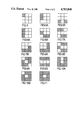
- FIGS. 4, 5A, 5B, 6A, 6B, 7A, 7B, 8A, 8B, 9A, 9B, 10A, 10B, and 11 show various pixel value subgroupings in accordance with the process of this invention.
- FIG. 1 a schematic block diagram of a system for practicing the method of this invention for processing and enhancing image data corresponding to a plurality of pixel values that may be derived from a two-dimensional photosensitive array.
- a plurality of image defining pixel values may be provided by a two-dimensional photosensitive area array comprising a high resolution charge coupled device (CCD) or charge injection device (CID) which receives image scene light in a well-known manner by way of an objective lens and shutter (not shown).
- the image sensing array comprises a plurality of image sensing elements or pixels preferably arranged in a two-dimensional area array, a portion of which is shown in FIG.
- each image sensing pixel X(0) through X(8) converts the incident image defining scene light rays into a corresponding analog signal value.
- the image sensing pixels X(0)-X(8) are arranged in columns and rows as is well known in the art.
- image sensing arrays particularly for sensing still images, comprise a substantially larger number of image sensing elements or pixels; and FIG. 2 illustrates only a small sample portion of a substantially larger image sensing array.
- a processor 12 of the image processing and enhancing system 10 of FIG. 1 receives each pixel value to be enhanced at input terminal A together with a select group of that pixel value's surrounding pixel values at input terminal B.
- the processor ultimately subgroups the surrounding pixel values in a manner to be more fully explained in accordance with whether the surrounding pixel values are closer to the pixel value to be enhanced or closest to that one of the surrounding pixel values having the greatest value difference from the pixel value to be enhanced.
- a pattern recognition circuit 14 determines as a function of the number of pixel values in each of the subgroups and the position of pixel values in each of the subgroups whether image sharpening or noise reduction should be promoted.
- the pattern recognition circuit 14 then provides the appropriate output signals to a filter coefficient circuit 16 in accordance with this determination.
- the filter coefficient circuit 16 responds to provide the appropriate filter coefficients for either noise reduction or image sharpening to an adaptive filter 18 which, in turn, operates to change the input pixel value to an output pixel value enhanced to promote either noise reduction or image sharpening as a function of the filter coefficients input thereto.
- a first pixel value X(0) is selected (block 20, FIG. 3) to be enhanced and input by way of terminal A to the processor 12 simultaneously with a select group of surrounding sampled pixel values X(1)-X(8) (block 22, FIG. 3).
- the select group of surrounding sampled pixel values X(1) through X(8) comprise the eight immediately surrounding pixel values to the center pixel value X(0) for which an enhanced pixel value is to be provided.
- the surrounding pixel values X(1) through X(8) are all assumed to be either greater in value or less in value than the center pixel value X(0).
- the processor 12 first operates to determine the absolute value difference between each pixel value of the select group of surrounding pixel values X(1) through X(8) and the pixel value X(0) to be enhanced (block 24, FIG. 3).
- the processor 12 arranges the eight pixel values X(1) through X(8) to rank order according to the aforementioned absolute value differences computed between each of the sampled group of surrounding pixel values X(1) through X(8) and the center pixel value X(0).
- the rank ordering is computationally accomplished by sorting the absolute value difference as shown in the following equation:
- the processor 12 retains the original numerically designated position of the surrounding pixel values X(1) through X(8) as shown in FIG. 2 to be subsequently used in the manner of this invention to recognize characteristic patterns of the pixel values.
- the group of surrounding pixel values X(1) through X(8) are next divided into subgroups (block 28, FIG. 3) in accordance with the determined absolute value differences with the center pixel value X(0).
- the first subgroup comprises those of the surrounding group of pixel values X(1) through X(8) which are closer in value to the determined pixel value having the greatest absolute value difference Z(8) than to the center pixel value X(0) which is to be enhanced.
- a second subgroup is determined comprising those of the surrounding pixel values X(1) through X(8) which are closer to the center pixel value to be enhanced than to the determined pixel value having the greatest absolute value difference Z(8).
- the first subgroup may be labeled w and determined in accordance with the following equation:
- Pattern recognition circuit 14 of FIG. 1 thereafter operates in the following manner (block 30, FIG. 3) to determine whether noise reduction or image sharpening should be promoted as a function of the number of pixel values in the first and second subgroups and the position of the pixel values in the first and second subgroups relative to each other.
- the pattern recognition circuit 14 signals the filter coefficient circuit 16 to provide the appropriate coefficients to the adaptive filter 18 to accomplish either the determined noise reduction or image sharpening (block 32 of FIG. 3).
- Pattern recognition first depends upon the number of pixel values of the surrounding pixel values X(1)-X(8) which are subgrouped in the first and second subgroups (w, u).
- the first subgroup (w) contains those pixel values having the greatest absolute value differences from the center pixel value X(0) and that the second subgroup (u) contains those pixel values having the least absolute value differences from the center pixel value X(0)
- FIG. 4 there is shown in FIG. 4 one example for the first possible combination of subgroupings where the first subgroup (w) contains one pixel value and the second subgroup (u) contains the remaining seven pixel values.
- the lone pixel value of the first subgroup (w) is shown cross hatched and occupies the upper lefthand corner position of the surrounding group of pixel values although it will be understood that it could occupy any one of the surrounding pixel value positions X(1) through X(8) as shown in FIG. 2.
- the pattern recognition circuit 14 in this case provides the appropriate signals to control the filter coefficient circuit 16 to apply the appropriate coefficients to the adaptive filter 18 to achieve image sharpening.
- the first subgroup (w) contains two pixel values and the second subgroup (u) contains six pixel values as shown in FIGS. 5A and 5B where the cross-hatched blocks represent pixel values of the first subgroup (w).
- FIGS. 5A and 5B where the cross-hatched blocks represent pixel values of the first subgroup (w).
- the pattern recognition circuit 14 signals the filter coefficient circuit 16 to apply the appropriate coefficients to the adaptive filter 18 to achieve noise reduction.
- the requirement of adjacency is computationally determined by taking the difference between the position designating numbers of the two pixel values of the first subgroup (w) as shown in FIG. 2. It is readily apparent from FIG. 2 that in order to determine adjacency the difference between the numbers designating the positions of any two pixel values must equal either 1 of 7. For the example shown in FIG. 5A the two pixel values correspond to X(1) and X(8), respectively, and the difference 8-1 meets the aforementioned computational requirement of 1 or 7 to establish adjacency. For the example shown in FIG. 5B, the two pixel values correspond to X(7) and X(5), respectively, and the difference 7-5 does not meet the computational requirement of 1 or 7 to establish adjacency.
- the pattern recognition circuit 14 controls the filter coefficients to promote image sharpening where the three pixel values of the first subgroup (w) are adjacent each other as shown in FIG. 6A. Again, adjacency is computationally determined in the aforementioned manner if the difference between any two pixel value position numbers as shown in FIG. 2 equals either 1 or 7. If the pixel values of the first subgroup (w) are not adjacent each other as, for example, shown in FIG. 6B, then this pattern is determined to be more likely representative of noise and, hence, the patterns recognition circuit 14 controls the filter coefficient circuit 16 to provide the appropriate coefficients to the adaptive filter 18 to promote noise reduction.
- the pattern recognition circuit 14 provides the appropriate control signals to promote edge enhancement as opposed to noise reduction since patterns of this type are more likely to be representative of a defined edge in the image than of noise.
- the pattern recognition circuit 14 provides the appropriate control signals to promote image sharpness if the three pixel values of the second subgroup (u) are located on a corner as shown in FIG. 8A.
- the pixel values must be adjacent each other and thus adjacency must first be determined in the manner as previously described.
- the three pixel values of the second subgroup (u) are determined to be adjacent with respect to each other, then it may be computationally determined whether the three adjacent pixel values are on the corner if the sum of the numbers designating the actual pixel value positions as shown in FIG. 2 add up to an odd number.
- FIG. 8A it can be seen that X(8)+X(1)+X(2) add up to 11 which is an odd number thereby meeting the dual requirements of both adjacency and being located on a corner so as to warrant the application of the edge sharpening coefficients.
- FIG. 8B it can be seen that the three pixel values of the second subgroup (u) are neither adjacent nor on a corner and thus are more likely to be indicative of noise so as to cause the pattern recognition circuit 14 to provide the appropriate control signals to promote noise reduction.
- the pattern recognition circuit 14 determines whether the two pixel values of the second subgroup (u) are antipodal as shown in the examples of FIGS. 9A and 9B. If the two pixel values of the second subgroup (u) are determined to be antipodal, then the pattern recognition circuit 14 provides the appropriate control signals to promote edge enhancement. If the two pixel values of the second subgroup (u) are not antipodal, then this pattern is more likely to be representative of noise, and the pattern recognition circuit 14 provides the appropriate control signals to promote noise reduction. Antipodality may be computationally determined if the absolute value difference between the two pixel values' numerical location as shown in FIG. 2 equals four.
- the absolute value difference between the pixel value X(1) and X(5) is four thereby verifying antipodality.
- the absolute value difference between the pixel value X(8) and X(4) is also four thereby also verifying antipodality.
- the pattern recognition circuit 14 provides the appropriate control signals to provide image sharpening when a pixel value of the second subgroup (u) is on the side as shown in FIG. 10A.
- the pixel value of the second subgroup (u) is on the corner as shown in FIG. 10B, then this pattern is more likely to be representative of noise, and the pattern recognition circuit 14 provides the appropriate control signals to promote noise reduction.
- pixel values located in corner positions have odd numbered designations such as X(1), X(3), X(5) and X(7).
- Pixel values having side positions have been numbered designations such as X(2), X(4), X(6) and X(8). Thus, whether a pixel value occupies a side or corner position can be computationally verified by determining whether the pixel value numerical designation is an odd or even number.
- the pattern recognition circuit 14 applies the appropriate control signals to promote image sharpening if the value difference between that pixel value of the first subgroup (w) having the greatest absolute value difference
- the adaptive filter 18 is provided with the appropriate filter coefficients to achieve either image sharpening or noise reduction as a function of the number of pixel values determined for the first and second subgroups (w), (u) and the position of the individual pixel values in the first and second subgroups as determined by the pattern recognition circuit 14. More specifically, the pattern recognition circuit 14 determines whether image sharpening or noise reduction will be promoted as a function of whether select ones of the pixel values of the first and second subgroups (w), (u) are adjacent, antipodal or on the side of corner of the select group of surrounding pixel values as shown in FIG. 2.
- the adaptive filter 18 promotes image sharpening upon receipt of the appropriate filter coefficients from circuit 16 to provide an enhanced output pixel value (block 32, FIG. 3) as a function of selectively weighting the average from the center pixel value X(0) to be enhanced and the select group of surrounding pixel values X(1)-X(8) as shown in FIG. 2.
- the adaptive filter 18 upon receipt of the appropriate noise reducing filter coefficients from the filter coefficient circuit 16 operates to provide an enhanced output pixel value by determining a nonweighted average from the center pixel value X(0) to be enhanced and the select group of surrounding pixel values X(1) through X(8) as shown in FIG. 2.
- the processor 12 operates in the aforementioned manner to take the absolute value difference between each pixel value of the select group of surrounding pixel values X(1)-X(8) and the pixel value X(0) to be enhanced (block 24 of FIG. 3).
- the processor 12 next rank orders the pixel values (block 26, FIG. 3) in accordance with the absolute value differences previously determined.
- the rank ordering of the absolute value differences for each of the select group of surrounding pixel values determines which one of the surrounding pixel values has the greatest absolute value difference
- the processor 12 thereafter operates to subgroup the pixel values X(1)-X(8) into a first subgroup (w) comprising those of the surrounding group of pixel values which are closer to the determined pixel value having the greatest absolute value difference
- a second subgroup (v) is also determined for those of the surrounding group of pixel values X(1)-X(8) of FIG. 2 whose value is outside the range of pixel values defined by the first subgroup (w) and which have absolute value differences from the center pixel value X(0) which are greater in value than one-half the greatest absolute value difference
- the second subgroup (v) of pixel values may be determined in accordance with the following computation:
- a third subgroup of pixel values (u) comprises those of the surrounding pixel values X(1)-X(8) of FIG. 2 which are not included in the first and second subgroups (w, v).
- the pattern recognition circuit 14 determines first whether there is one or more pixel values in the second subgroup (v). In the event that no pixel values come within the second subgroup (v), then pattern recognition continues in the previously described manner where the pixel values in the above-described third subgroup (u) are treated in the previously described manner in regard to the second subgroup. However, in the event that one or more pixel values are included in the second subgroup (v), then the pattern recognition circuit 14 determines whether the two pixel values of the second subgroup (v) which are closest in value to the center pixel value X(0) are antipodal. Again, antipodality is determined in the above-described manner.
- the pattern recognition circuit 14 If the two closest pixel values of the second subgroup (v) are determined to be antipodal, then the pattern recognition circuit 14 provides the appropriate control signals to promote image sharpening. Conversely, if the two pixel values of the second subgroup (v) closest in value to the center pixel value X(0) are determined not to be antipodal, then the pattern recognition circuit 14 provides the appropriate control signals to promote noise reduction.
- the image enhancing process of this invention is by no means so limited and eight pixel values may be sampled from a substantially larger area of pixel values surrounding the center pixel X(0). Alternatively, more or less than eight pixel values may also be sampled. It will also be readily understood that the pixel values could also be representative of red, green or blue image data in a color imaging system or, alternatively, the pixel values could be representative of luminance image data.
Abstract
Description
Z(J)=ABS SORT [D(i):i=1, 2 . . . , 8]
J=1, 2, . . . 8
|Z(1)|<|Z(2)|<. . . <|Z(8)|
w={J:|Z(8)|-|Z(J)|<|Z(J).vertline.}
u={J:all JΣw}
w={J:|Z(8)|-|Z(J)|<|Z(J).vertline. and Z(8)Z(J)>}
v={J:|Z(8)|-|Z(J)|<|Z(J).vertline. and Z(8)Z(J)<0}
Claims (18)
Priority Applications (6)
| Application Number | Priority Date | Filing Date | Title |
|---|---|---|---|
| US07/128,937 US4783840A (en) | 1987-12-04 | 1987-12-04 | Method for enhancing image data by noise reduction or sharpening |
| EP19880119691 EP0318866A3 (en) | 1987-12-04 | 1988-11-25 | Method for enhancing image data by noise reduction or sharpening |
| DE198888119691T DE318866T1 (en) | 1987-12-04 | 1988-11-25 | METHOD FOR IMPROVING IMAGE DATA THROUGH NOISE REDUCTION OR DIFFERENTIATION. |
| JP63305882A JPH01265370A (en) | 1987-12-04 | 1988-12-02 | Intensifying of image data |
| CA000584901A CA1295415C (en) | 1987-12-04 | 1988-12-02 | Method for enhancing image data by noise reduction or sharpening |
| KR1019880016132A KR890011386A (en) | 1987-12-04 | 1988-12-03 | Image Data Enhancement Method by Noise Reduction or Sharpening |
Applications Claiming Priority (1)
| Application Number | Priority Date | Filing Date | Title |
|---|---|---|---|
| US07/128,937 US4783840A (en) | 1987-12-04 | 1987-12-04 | Method for enhancing image data by noise reduction or sharpening |
Publications (1)
| Publication Number | Publication Date |
|---|---|
| US4783840A true US4783840A (en) | 1988-11-08 |
Family
ID=22437709
Family Applications (1)
| Application Number | Title | Priority Date | Filing Date |
|---|---|---|---|
| US07/128,937 Expired - Lifetime US4783840A (en) | 1987-12-04 | 1987-12-04 | Method for enhancing image data by noise reduction or sharpening |
Country Status (6)
| Country | Link |
|---|---|
| US (1) | US4783840A (en) |
| EP (1) | EP0318866A3 (en) |
| JP (1) | JPH01265370A (en) |
| KR (1) | KR890011386A (en) |
| CA (1) | CA1295415C (en) |
| DE (1) | DE318866T1 (en) |
Cited By (78)
| Publication number | Priority date | Publication date | Assignee | Title |
|---|---|---|---|---|
| EP0398861A2 (en) * | 1989-05-15 | 1990-11-22 | Polaroid Corporation | Method for adaptively sharpening electronic images |
| US4975864A (en) * | 1989-01-26 | 1990-12-04 | Hughes Aircraft Company | Scene based nonuniformity compensation for starting focal plane arrays |
| US4985618A (en) * | 1988-06-16 | 1991-01-15 | Nicoh Company, Ltd. | Parallel image processing system |
| EP0415648A2 (en) * | 1989-08-31 | 1991-03-06 | Canon Kabushiki Kaisha | Image processing apparatus |
| US5003618A (en) * | 1989-07-14 | 1991-03-26 | University Of Pittsburgh Of The Commonwealth System Of Higher Education | Automatic adaptive anisotropic digital filtering and biasing of digitized images |
| US5036405A (en) * | 1986-11-19 | 1991-07-30 | Canon Kabushiki Kaisha | Image amending method |
| US5054100A (en) * | 1989-11-16 | 1991-10-01 | Eastman Kodak Company | Pixel interpolator with edge sharpening |
| US5121209A (en) * | 1990-10-01 | 1992-06-09 | Rca Licensing Corporation | Sharpness control for a television image |
| US5128525A (en) * | 1990-07-31 | 1992-07-07 | Xerox Corporation | Convolution filtering for decoding self-clocking glyph shape codes |
| US5131057A (en) * | 1990-02-12 | 1992-07-14 | Wright State University | Method for video-to-printing image resolution conversion |
| US5164997A (en) * | 1990-01-30 | 1992-11-17 | Ezel, Inc. | Method and apparatus for aligning images using pixels of closed contours |
| US5168375A (en) * | 1991-09-18 | 1992-12-01 | Polaroid Corporation | Image reconstruction by use of discrete cosine and related transforms |
| WO1993006693A1 (en) * | 1991-09-17 | 1993-04-01 | Moore Color, Inc. | Saturable smoothing grid for image processing |
| US5210688A (en) * | 1990-05-21 | 1993-05-11 | General Motors Corporation | Sinography method and apparatus |
| US5218460A (en) * | 1990-04-19 | 1993-06-08 | Fuji Photo Film Co., Ltd. | Method for pattern selection involving scaling-up circumscribed rectangles |
| US5241372A (en) * | 1990-11-30 | 1993-08-31 | Sony Corporation | Video image processing apparatus including convolution filter means to process pixels of a video image by a set of parameter coefficients |
| US5271064A (en) * | 1991-06-14 | 1993-12-14 | University Of Cincinnati | Apparatus and method for smoothing regions and enhancing edges in gray scale images |
| US5341174A (en) * | 1992-08-17 | 1994-08-23 | Wright State University | Motion compensated resolution conversion system |
| US5343309A (en) * | 1992-08-12 | 1994-08-30 | Xerox Corporation | Image processing system and method employing adaptive filtering to provide improved reconstruction of continuous tone images from halftone images including those without a screen structure |
| US5357581A (en) * | 1991-11-01 | 1994-10-18 | Eastman Kodak Company | Method and apparatus for the selective filtering of dot-matrix printed characters so as to improve optical character recognition |
| US5384866A (en) * | 1992-04-02 | 1995-01-24 | Ezel, Inc. | Thinning method of an image |
| US5410614A (en) * | 1993-10-22 | 1995-04-25 | Industrial Technology Research Institute | Run-based method for smoothing handwritten Chinese characters |
| US5559902A (en) * | 1991-12-23 | 1996-09-24 | Lucent Technologies Inc. | Method for enhancing connected and degraded text recognition |
| US5572603A (en) * | 1992-05-20 | 1996-11-05 | Ricoh Company, Ltd. | Image processing method and device using such method |
| US5579414A (en) * | 1992-10-19 | 1996-11-26 | Fast; Bruce B. | OCR image preprocessing method for image enhancement of scanned documents by reversing invert text |
| US5621823A (en) * | 1988-12-30 | 1997-04-15 | Yozan, Inc. | Image processing method for thinning lines using index values |
| US5625421A (en) * | 1994-01-14 | 1997-04-29 | Yves C. Faroudja | Suppression of sawtooth artifacts in an interlace-to-progressive converted signal |
| US5631979A (en) * | 1992-10-26 | 1997-05-20 | Eastman Kodak Company | Pixel value estimation technique using non-linear prediction |
| US5644513A (en) * | 1989-12-22 | 1997-07-01 | Rudin; Leonid I. | System incorporating feature-oriented signal enhancement using shock filters |
| EP0788070A2 (en) * | 1996-01-31 | 1997-08-06 | EASTMAN KODAK COMPANY (a New Jersey corporation) | Method for forming a digital sharpening/blurring filter |
| US5689587A (en) * | 1996-02-09 | 1997-11-18 | Massachusetts Institute Of Technology | Method and apparatus for data hiding in images |
| US5708919A (en) * | 1995-05-02 | 1998-01-13 | Minolta Co., Ltd. | Imaging forming apparatus for forming images on both surfaces of recording medium |
| US5740340A (en) * | 1993-08-09 | 1998-04-14 | C-Cube Microsystems, Inc. | 2-dimensional memory allowing access both as rows of data words and columns of data words |
| US5802212A (en) * | 1996-02-09 | 1998-09-01 | Seiko Epson Corporation | Clustered-dot dither with white-fleck suppression |
| US5805216A (en) * | 1994-06-06 | 1998-09-08 | Matsushita Electric Industrial Co., Ltd. | Defective pixel correction circuit |
| US5815605A (en) * | 1992-07-17 | 1998-09-29 | Ricoh Company, Ltd. | Image processing system and method |
| US5825937A (en) * | 1993-09-27 | 1998-10-20 | Ricoh Company, Ltd. | Spatial-filtering unit for performing adaptive edge-enhancement process |
| US5828792A (en) * | 1993-10-15 | 1998-10-27 | Lucent Technologies, Inc. | Method of reducing document size for digital display |
| US5838371A (en) * | 1993-03-05 | 1998-11-17 | Canon Kabushiki Kaisha | Image pickup apparatus with interpolation and edge enhancement of pickup signal varying with zoom magnification |
| US5867606A (en) * | 1997-08-12 | 1999-02-02 | Hewlett-Packard Company | Apparatus and method for determining the appropriate amount of sharpening for an image |
| US5910909A (en) * | 1995-08-28 | 1999-06-08 | C-Cube Microsystems, Inc. | Non-linear digital filters for interlaced video signals and method thereof |
| US5946454A (en) * | 1996-08-15 | 1999-08-31 | Seiko Epson Corporation | Image enhancement during half-toning using low-pass and high-pass filtering |
| US5959693A (en) * | 1997-05-07 | 1999-09-28 | General Instrument Corporation | Pixel adaptive noise reduction filter for digital video |
| US6043853A (en) * | 1996-04-12 | 2000-03-28 | Sony Corporation | Apparatus and method for emphasizing an outline of a video signal |
| US6075926A (en) * | 1997-04-21 | 2000-06-13 | Hewlett-Packard Company | Computerized method for improving data resolution |
| US6111975A (en) * | 1991-03-22 | 2000-08-29 | Sacks; Jack M. | Minimum difference processor |
| US6118906A (en) * | 1998-02-03 | 2000-09-12 | Eastman Kodak Company | Sharpening system adjusted for measured noise of photofinishing images |
| US6195467B1 (en) | 1999-03-25 | 2001-02-27 | Image Processing Technologies, Inc. | Method and apparatus for sharpening a grayscale image |
| US6346970B1 (en) * | 1998-08-12 | 2002-02-12 | Focus Enhancements, Inc. | Two-dimensional adjustable flicker filter |
| US20020047907A1 (en) * | 2000-08-30 | 2002-04-25 | Nikon Corporation | Image processing apparatus and storage medium for storing image processing program |
| US6424730B1 (en) | 1998-11-03 | 2002-07-23 | Eastman Kodak Company | Medical image enhancement method for hardcopy prints |
| US20020140864A1 (en) * | 2001-03-28 | 2002-10-03 | Koninklijke Philips Electronics N.V. | System and method for performing segmentation-based enhancements of a video image |
| US20020181798A1 (en) * | 2000-03-24 | 2002-12-05 | Ojo Olukayode Anthony | N-dimensional filter and method for n-dimensionally filtering an original image pixel |
| US6535254B1 (en) * | 1997-10-31 | 2003-03-18 | Pinnacle Systems Inc. | Method and device for noise reduction |
| US20030071909A1 (en) * | 2001-10-11 | 2003-04-17 | Peters Geoffrey W. | Generating images of objects at different focal lengths |
| US6614474B1 (en) | 1998-08-27 | 2003-09-02 | Polycom, Inc. | Electronic pan tilt zoom video camera with adaptive edge sharpening filter |
| US6628329B1 (en) | 1998-08-26 | 2003-09-30 | Eastman Kodak Company | Correction of position dependent blur in a digital image |
| US20030198400A1 (en) * | 2002-04-19 | 2003-10-23 | Timothy Alderson | Scene-based non-uniformity offset correction for staring arrays |
| US20030228067A1 (en) * | 2002-06-05 | 2003-12-11 | Canon Kabushiki Kaisha | Image processing apparatus, image processing method, and computer program |
| US6665447B1 (en) * | 1999-07-26 | 2003-12-16 | Hewlett-Packard Development Company, L.P. | Method for enhancing image data by sharpening |
| US20040012721A1 (en) * | 2002-07-16 | 2004-01-22 | Alvarez Jose Roberto | Adaptive non-linear noise reduction techniques |
| US6721458B1 (en) * | 2000-04-14 | 2004-04-13 | Seiko Epson Corporation | Artifact reduction using adaptive nonlinear filters |
| US20040081366A1 (en) * | 2002-10-16 | 2004-04-29 | Yusuke Monobe | Image processing apparatus and image processing method |
| US20040125387A1 (en) * | 2002-12-27 | 2004-07-01 | Fuji Xerox Co., Ltd. | Image processing apparatus, image processing method and program therefor |
| US20040190786A1 (en) * | 2003-03-24 | 2004-09-30 | Khageshwar Thakur | Method of image enhancement for an imaging apparatus |
| US6801339B1 (en) * | 1998-03-26 | 2004-10-05 | Fuji Photo Film Co., Ltd. | Image processing method and apparatus |
| US20050180654A1 (en) * | 2004-02-18 | 2005-08-18 | Huaya Microelectronics (Shanghai) Inc. | Directional interpolative smoother |
| US7110599B1 (en) * | 1999-03-05 | 2006-09-19 | Seiko Epson Corporation | Image data retouching apparatus, image data retouching method, and medium on which image data retouching program is recorded |
| US20070201759A1 (en) * | 2006-02-24 | 2007-08-30 | Pixart Imaging Inc., R.O.C. | Digital image processing apparatus and method for the same |
| US20080152248A1 (en) * | 2006-12-22 | 2008-06-26 | Kelly Sean C | Reduction of position dependent noise in a digital image |
| US20080212895A1 (en) * | 2007-01-09 | 2008-09-04 | Lockheed Martin Corporation | Image data processing techniques for highly undersampled images |
| US20090046200A1 (en) * | 2007-08-15 | 2009-02-19 | Yang-Po Chiu | Image capture device with detachable expansion unit |
| US7508430B1 (en) * | 2005-02-18 | 2009-03-24 | Magnachip Semiconductor, Ltd. | Method for locally reducing row noise |
| US20090153739A1 (en) * | 2007-12-14 | 2009-06-18 | Texas Instruments Incorporated | Method and Apparatus for a Noise Filter for Reducing Noise in a Image or Video |
| US7822284B2 (en) | 1989-05-22 | 2010-10-26 | Carl Cooper | Spatial scan replication circuit |
| US20120307038A1 (en) * | 2010-02-09 | 2012-12-06 | Hitachi High-Technologies Corporation | Charged particle beam apparatus |
| US20130089269A1 (en) * | 2011-10-07 | 2013-04-11 | Texas Instruments Incorporated | Scene Adaptive Filter Design for Improved Stereo Matching |
| US10699385B2 (en) * | 2017-05-24 | 2020-06-30 | Canon Kabushiki Kaisha | Image processing apparatus, image processing method, and storage medium |
Families Citing this family (9)
| Publication number | Priority date | Publication date | Assignee | Title |
|---|---|---|---|---|
| EP0440786A1 (en) * | 1989-08-28 | 1991-08-14 | Eastman Kodak Company | A computer based digital image noise reduction method based on overlapping planar approximation |
| EP0645736B1 (en) * | 1993-09-27 | 2003-02-05 | Canon Kabushiki Kaisha | Image processing apparatus |
| US5768482A (en) * | 1995-06-14 | 1998-06-16 | Hewlett-Packard Company | Resolution-triggered sharpening for scaling of a digital-matrix image |
| AU727553B2 (en) * | 1997-10-08 | 2000-12-14 | Canon Kabushiki Kaisha | Improvements in Image Filtering |
| US6135962A (en) * | 1998-12-01 | 2000-10-24 | General Electric Company | Method and apparatus for adaptive filtering by counting acoustic sample zeroes in ultrasound imaging |
| US6970268B1 (en) | 1999-02-05 | 2005-11-29 | Samsung Electronics Co., Ltd. | Color image processing method and apparatus thereof |
| EP1153364A4 (en) * | 1999-02-05 | 2002-10-30 | Samsung Electronics Co Ltd | Color image processing method and apparatus thereof |
| US20040169872A1 (en) * | 2003-02-28 | 2004-09-02 | Maurer Ron P. | Blind inverse halftoning |
| JP5926043B2 (en) * | 2011-12-02 | 2016-05-25 | 三星電子株式会社Samsung Electronics Co.,Ltd. | Information processing apparatus and information processing method |
Citations (8)
| Publication number | Priority date | Publication date | Assignee | Title |
|---|---|---|---|---|
| US4003024A (en) * | 1975-10-14 | 1977-01-11 | Rockwell International Corporation | Two-dimensional binary data enhancement system |
| US4290049A (en) * | 1979-09-10 | 1981-09-15 | Environmental Research Institute Of Michigan | Dynamic data correction generator for an image analyzer system |
| US4311914A (en) * | 1978-12-18 | 1982-01-19 | Gretag Aktiengesellschaft | Process for assessing the quality of a printed product |
| US4520505A (en) * | 1981-12-23 | 1985-05-28 | Mitsubishi Denki Kabushiki Kaisha | Character reading device |
| US4541116A (en) * | 1984-02-27 | 1985-09-10 | Environmental Research Institute Of Mi | Neighborhood image processing stage for implementing filtering operations |
| US4663655A (en) * | 1985-08-05 | 1987-05-05 | Polaroid Corporation | Method and apparatus for reconstructing missing color samples |
| US4691366A (en) * | 1983-11-13 | 1987-09-01 | Elscint Ltd. | Image enhancement |
| US4724544A (en) * | 1984-06-09 | 1988-02-09 | Fuji Photo Film Co., Ltd. | Method of processing image signal |
-
1987
- 1987-12-04 US US07/128,937 patent/US4783840A/en not_active Expired - Lifetime
-
1988
- 1988-11-25 DE DE198888119691T patent/DE318866T1/en active Pending
- 1988-11-25 EP EP19880119691 patent/EP0318866A3/en not_active Withdrawn
- 1988-12-02 CA CA000584901A patent/CA1295415C/en not_active Expired - Fee Related
- 1988-12-02 JP JP63305882A patent/JPH01265370A/en active Pending
- 1988-12-03 KR KR1019880016132A patent/KR890011386A/en not_active Application Discontinuation
Patent Citations (8)
| Publication number | Priority date | Publication date | Assignee | Title |
|---|---|---|---|---|
| US4003024A (en) * | 1975-10-14 | 1977-01-11 | Rockwell International Corporation | Two-dimensional binary data enhancement system |
| US4311914A (en) * | 1978-12-18 | 1982-01-19 | Gretag Aktiengesellschaft | Process for assessing the quality of a printed product |
| US4290049A (en) * | 1979-09-10 | 1981-09-15 | Environmental Research Institute Of Michigan | Dynamic data correction generator for an image analyzer system |
| US4520505A (en) * | 1981-12-23 | 1985-05-28 | Mitsubishi Denki Kabushiki Kaisha | Character reading device |
| US4691366A (en) * | 1983-11-13 | 1987-09-01 | Elscint Ltd. | Image enhancement |
| US4541116A (en) * | 1984-02-27 | 1985-09-10 | Environmental Research Institute Of Mi | Neighborhood image processing stage for implementing filtering operations |
| US4724544A (en) * | 1984-06-09 | 1988-02-09 | Fuji Photo Film Co., Ltd. | Method of processing image signal |
| US4663655A (en) * | 1985-08-05 | 1987-05-05 | Polaroid Corporation | Method and apparatus for reconstructing missing color samples |
Cited By (115)
| Publication number | Priority date | Publication date | Assignee | Title |
|---|---|---|---|---|
| US5036405A (en) * | 1986-11-19 | 1991-07-30 | Canon Kabushiki Kaisha | Image amending method |
| US4985618A (en) * | 1988-06-16 | 1991-01-15 | Nicoh Company, Ltd. | Parallel image processing system |
| US5621823A (en) * | 1988-12-30 | 1997-04-15 | Yozan, Inc. | Image processing method for thinning lines using index values |
| US4975864A (en) * | 1989-01-26 | 1990-12-04 | Hughes Aircraft Company | Scene based nonuniformity compensation for starting focal plane arrays |
| EP0398861A3 (en) * | 1989-05-15 | 1992-10-07 | Polaroid Corporation | Method for adaptively sharpening electronic images |
| EP0398861A2 (en) * | 1989-05-15 | 1990-11-22 | Polaroid Corporation | Method for adaptively sharpening electronic images |
| US5038388A (en) * | 1989-05-15 | 1991-08-06 | Polaroid Corporation | Method for adaptively sharpening electronic images |
| US7986851B2 (en) | 1989-05-22 | 2011-07-26 | Cooper J Carl | Spatial scan replication circuit |
| US7822284B2 (en) | 1989-05-22 | 2010-10-26 | Carl Cooper | Spatial scan replication circuit |
| US5003618A (en) * | 1989-07-14 | 1991-03-26 | University Of Pittsburgh Of The Commonwealth System Of Higher Education | Automatic adaptive anisotropic digital filtering and biasing of digitized images |
| US5339365A (en) * | 1989-08-31 | 1994-08-16 | Canon Kabushiki Kaisha | Image processing apparatus capable of using fuzzy logic |
| EP0415648A2 (en) * | 1989-08-31 | 1991-03-06 | Canon Kabushiki Kaisha | Image processing apparatus |
| EP0415648A3 (en) * | 1989-08-31 | 1992-04-08 | Canon Kabushiki Kaisha | Image processing apparatus |
| US5870491A (en) * | 1989-08-31 | 1999-02-09 | Canon Kabushiki Kaisha | Image processing apparatus which controls processing conditions of an image signal on detected features of the image signal |
| US5054100A (en) * | 1989-11-16 | 1991-10-01 | Eastman Kodak Company | Pixel interpolator with edge sharpening |
| US5644513A (en) * | 1989-12-22 | 1997-07-01 | Rudin; Leonid I. | System incorporating feature-oriented signal enhancement using shock filters |
| US5164997A (en) * | 1990-01-30 | 1992-11-17 | Ezel, Inc. | Method and apparatus for aligning images using pixels of closed contours |
| US5131057A (en) * | 1990-02-12 | 1992-07-14 | Wright State University | Method for video-to-printing image resolution conversion |
| US5218460A (en) * | 1990-04-19 | 1993-06-08 | Fuji Photo Film Co., Ltd. | Method for pattern selection involving scaling-up circumscribed rectangles |
| US5210688A (en) * | 1990-05-21 | 1993-05-11 | General Motors Corporation | Sinography method and apparatus |
| US5128525A (en) * | 1990-07-31 | 1992-07-07 | Xerox Corporation | Convolution filtering for decoding self-clocking glyph shape codes |
| US5121209A (en) * | 1990-10-01 | 1992-06-09 | Rca Licensing Corporation | Sharpness control for a television image |
| US5241372A (en) * | 1990-11-30 | 1993-08-31 | Sony Corporation | Video image processing apparatus including convolution filter means to process pixels of a video image by a set of parameter coefficients |
| US6111975A (en) * | 1991-03-22 | 2000-08-29 | Sacks; Jack M. | Minimum difference processor |
| US5271064A (en) * | 1991-06-14 | 1993-12-14 | University Of Cincinnati | Apparatus and method for smoothing regions and enhancing edges in gray scale images |
| WO1993006693A1 (en) * | 1991-09-17 | 1993-04-01 | Moore Color, Inc. | Saturable smoothing grid for image processing |
| US5294989A (en) * | 1991-09-17 | 1994-03-15 | Moore Color, Inc. | Saturable smoothing grid for image processing |
| US5168375A (en) * | 1991-09-18 | 1992-12-01 | Polaroid Corporation | Image reconstruction by use of discrete cosine and related transforms |
| US5357581A (en) * | 1991-11-01 | 1994-10-18 | Eastman Kodak Company | Method and apparatus for the selective filtering of dot-matrix printed characters so as to improve optical character recognition |
| US5559902A (en) * | 1991-12-23 | 1996-09-24 | Lucent Technologies Inc. | Method for enhancing connected and degraded text recognition |
| US5644648A (en) * | 1991-12-23 | 1997-07-01 | Lucent Technologies Inc. | Method and apparatus for connected and degraded text recognition |
| US5384866A (en) * | 1992-04-02 | 1995-01-24 | Ezel, Inc. | Thinning method of an image |
| US5572603A (en) * | 1992-05-20 | 1996-11-05 | Ricoh Company, Ltd. | Image processing method and device using such method |
| US5815605A (en) * | 1992-07-17 | 1998-09-29 | Ricoh Company, Ltd. | Image processing system and method |
| US5343309A (en) * | 1992-08-12 | 1994-08-30 | Xerox Corporation | Image processing system and method employing adaptive filtering to provide improved reconstruction of continuous tone images from halftone images including those without a screen structure |
| US5341174A (en) * | 1992-08-17 | 1994-08-23 | Wright State University | Motion compensated resolution conversion system |
| US5590224A (en) * | 1992-10-19 | 1996-12-31 | Fast; Bruce B. | OCR image preprocessing method for image enhancement of scanned documents by correction of registration |
| US5594817A (en) * | 1992-10-19 | 1997-01-14 | Fast; Bruce B. | OCR image pre-processor for detecting and reducing skew of the image of textual matter of a scanned document |
| US5625719A (en) * | 1992-10-19 | 1997-04-29 | Fast; Bruce B. | OCR image preprocessing method for image enhancement of scanned documents |
| US5579414A (en) * | 1992-10-19 | 1996-11-26 | Fast; Bruce B. | OCR image preprocessing method for image enhancement of scanned documents by reversing invert text |
| US5594814A (en) * | 1992-10-19 | 1997-01-14 | Fast; Bruce B. | OCR image preprocessing method for image enhancement of scanned documents |
| US5729635A (en) * | 1992-10-19 | 1998-03-17 | Tmssequoia | OCR image free-processing method for image enhancement of scanned documents |
| US5594815A (en) * | 1992-10-19 | 1997-01-14 | Fast; Bruce B. | OCR image preprocessing method for image enhancement of scanned documents |
| US5631979A (en) * | 1992-10-26 | 1997-05-20 | Eastman Kodak Company | Pixel value estimation technique using non-linear prediction |
| US5838371A (en) * | 1993-03-05 | 1998-11-17 | Canon Kabushiki Kaisha | Image pickup apparatus with interpolation and edge enhancement of pickup signal varying with zoom magnification |
| US6122442A (en) * | 1993-08-09 | 2000-09-19 | C-Cube Microsystems, Inc. | Structure and method for motion estimation of a digital image by matching derived scores |
| US6071004A (en) * | 1993-08-09 | 2000-06-06 | C-Cube Microsystems, Inc. | Non-linear digital filters for interlaced video signals and method thereof |
| US5740340A (en) * | 1993-08-09 | 1998-04-14 | C-Cube Microsystems, Inc. | 2-dimensional memory allowing access both as rows of data words and columns of data words |
| US5825937A (en) * | 1993-09-27 | 1998-10-20 | Ricoh Company, Ltd. | Spatial-filtering unit for performing adaptive edge-enhancement process |
| US5828792A (en) * | 1993-10-15 | 1998-10-27 | Lucent Technologies, Inc. | Method of reducing document size for digital display |
| US5410614A (en) * | 1993-10-22 | 1995-04-25 | Industrial Technology Research Institute | Run-based method for smoothing handwritten Chinese characters |
| US5625421A (en) * | 1994-01-14 | 1997-04-29 | Yves C. Faroudja | Suppression of sawtooth artifacts in an interlace-to-progressive converted signal |
| US5805216A (en) * | 1994-06-06 | 1998-09-08 | Matsushita Electric Industrial Co., Ltd. | Defective pixel correction circuit |
| US5708919A (en) * | 1995-05-02 | 1998-01-13 | Minolta Co., Ltd. | Imaging forming apparatus for forming images on both surfaces of recording medium |
| US5910909A (en) * | 1995-08-28 | 1999-06-08 | C-Cube Microsystems, Inc. | Non-linear digital filters for interlaced video signals and method thereof |
| EP0788070A3 (en) * | 1996-01-31 | 1998-08-19 | EASTMAN KODAK COMPANY (a New Jersey corporation) | Method for forming a digital sharpening/blurring filter |
| EP0788070A2 (en) * | 1996-01-31 | 1997-08-06 | EASTMAN KODAK COMPANY (a New Jersey corporation) | Method for forming a digital sharpening/blurring filter |
| US5802212A (en) * | 1996-02-09 | 1998-09-01 | Seiko Epson Corporation | Clustered-dot dither with white-fleck suppression |
| US5870499A (en) * | 1996-02-09 | 1999-02-09 | Massachusetts Institute Of Technology | Method and apparatus for data hiding in images |
| US5689587A (en) * | 1996-02-09 | 1997-11-18 | Massachusetts Institute Of Technology | Method and apparatus for data hiding in images |
| US6043853A (en) * | 1996-04-12 | 2000-03-28 | Sony Corporation | Apparatus and method for emphasizing an outline of a video signal |
| US5946454A (en) * | 1996-08-15 | 1999-08-31 | Seiko Epson Corporation | Image enhancement during half-toning using low-pass and high-pass filtering |
| US6466702B1 (en) | 1997-04-21 | 2002-10-15 | Hewlett-Packard Company | Apparatus and method of building an electronic database for resolution synthesis |
| US6075926A (en) * | 1997-04-21 | 2000-06-13 | Hewlett-Packard Company | Computerized method for improving data resolution |
| US5959693A (en) * | 1997-05-07 | 1999-09-28 | General Instrument Corporation | Pixel adaptive noise reduction filter for digital video |
| US5867606A (en) * | 1997-08-12 | 1999-02-02 | Hewlett-Packard Company | Apparatus and method for determining the appropriate amount of sharpening for an image |
| US6535254B1 (en) * | 1997-10-31 | 2003-03-18 | Pinnacle Systems Inc. | Method and device for noise reduction |
| US6118906A (en) * | 1998-02-03 | 2000-09-12 | Eastman Kodak Company | Sharpening system adjusted for measured noise of photofinishing images |
| US6801339B1 (en) * | 1998-03-26 | 2004-10-05 | Fuji Photo Film Co., Ltd. | Image processing method and apparatus |
| US6346970B1 (en) * | 1998-08-12 | 2002-02-12 | Focus Enhancements, Inc. | Two-dimensional adjustable flicker filter |
| US6628329B1 (en) | 1998-08-26 | 2003-09-30 | Eastman Kodak Company | Correction of position dependent blur in a digital image |
| US7471320B2 (en) | 1998-08-27 | 2008-12-30 | Polycom, Inc. | Electronic pan tilt zoom video camera with adaptive edge sharpening filter |
| US6614474B1 (en) | 1998-08-27 | 2003-09-02 | Polycom, Inc. | Electronic pan tilt zoom video camera with adaptive edge sharpening filter |
| US20030193584A1 (en) * | 1998-08-27 | 2003-10-16 | Malkin Kenneth W. | Electronic pan tilt zoom video camera with adaptive edge sharpening filter |
| US6424730B1 (en) | 1998-11-03 | 2002-07-23 | Eastman Kodak Company | Medical image enhancement method for hardcopy prints |
| US7110599B1 (en) * | 1999-03-05 | 2006-09-19 | Seiko Epson Corporation | Image data retouching apparatus, image data retouching method, and medium on which image data retouching program is recorded |
| US6195467B1 (en) | 1999-03-25 | 2001-02-27 | Image Processing Technologies, Inc. | Method and apparatus for sharpening a grayscale image |
| US6665447B1 (en) * | 1999-07-26 | 2003-12-16 | Hewlett-Packard Development Company, L.P. | Method for enhancing image data by sharpening |
| US7162099B2 (en) * | 2000-03-24 | 2007-01-09 | Koninklijke Philips Electronics N.V. | N-dimensional filter and method for n-dimensionally filtering an original image pixel |
| US20020181798A1 (en) * | 2000-03-24 | 2002-12-05 | Ojo Olukayode Anthony | N-dimensional filter and method for n-dimensionally filtering an original image pixel |
| US6721458B1 (en) * | 2000-04-14 | 2004-04-13 | Seiko Epson Corporation | Artifact reduction using adaptive nonlinear filters |
| US20020047907A1 (en) * | 2000-08-30 | 2002-04-25 | Nikon Corporation | Image processing apparatus and storage medium for storing image processing program |
| US20020140864A1 (en) * | 2001-03-28 | 2002-10-03 | Koninklijke Philips Electronics N.V. | System and method for performing segmentation-based enhancements of a video image |
| US6903782B2 (en) * | 2001-03-28 | 2005-06-07 | Koninklijke Philips Electronics N.V. | System and method for performing segmentation-based enhancements of a video image |
| US20030071909A1 (en) * | 2001-10-11 | 2003-04-17 | Peters Geoffrey W. | Generating images of objects at different focal lengths |
| US7016550B2 (en) * | 2002-04-19 | 2006-03-21 | Lockheed Martin Corporation | Scene-based non-uniformity offset correction for staring arrays |
| US20030198400A1 (en) * | 2002-04-19 | 2003-10-23 | Timothy Alderson | Scene-based non-uniformity offset correction for staring arrays |
| US8306357B2 (en) | 2002-06-05 | 2012-11-06 | Canon Kabushiki Kaisha | Image processing apparatus, image processing method, and computer program |
| US20030228067A1 (en) * | 2002-06-05 | 2003-12-11 | Canon Kabushiki Kaisha | Image processing apparatus, image processing method, and computer program |
| US8023764B2 (en) * | 2002-06-05 | 2011-09-20 | Canon Kabushiki Kaisha | Image processing apparatus, image processing method, and a program, for removing low-frequency noise from image data |
| US8744209B2 (en) | 2002-06-05 | 2014-06-03 | Canon Kabushiki Kaisha | Image processing apparatus and image processing method for visually reducing noise components contained in a low frequency range of image data |
| US6958783B2 (en) * | 2002-07-16 | 2005-10-25 | Broadcom Corporation | Adaptive non-linear noise reduction techniques |
| US20050243213A1 (en) * | 2002-07-16 | 2005-11-03 | Alvarez Jose R | Adaptive non-linear noise reduction techniques |
| US20040012721A1 (en) * | 2002-07-16 | 2004-01-22 | Alvarez Jose Roberto | Adaptive non-linear noise reduction techniques |
| US7158189B2 (en) * | 2002-07-16 | 2007-01-02 | Broadcom Corporation | Adaptive non-linear noise reduction techniques |
| US7292733B2 (en) * | 2002-10-16 | 2007-11-06 | Matsushita Electric Industrial Co., Ltd. | Image processing apparatus and image processing method |
| US20040081366A1 (en) * | 2002-10-16 | 2004-04-29 | Yusuke Monobe | Image processing apparatus and image processing method |
| US7663779B2 (en) * | 2002-12-27 | 2010-02-16 | Fuji Xerox Co., Ltd. | Image processing apparatus, image processing method and program therefor |
| US20040125387A1 (en) * | 2002-12-27 | 2004-07-01 | Fuji Xerox Co., Ltd. | Image processing apparatus, image processing method and program therefor |
| US20040190786A1 (en) * | 2003-03-24 | 2004-09-30 | Khageshwar Thakur | Method of image enhancement for an imaging apparatus |
| US7505083B2 (en) * | 2004-02-18 | 2009-03-17 | Huaya Microelectronics, Ltd. | Directional interpolative smoother |
| US20050180654A1 (en) * | 2004-02-18 | 2005-08-18 | Huaya Microelectronics (Shanghai) Inc. | Directional interpolative smoother |
| US7508430B1 (en) * | 2005-02-18 | 2009-03-24 | Magnachip Semiconductor, Ltd. | Method for locally reducing row noise |
| US20070201759A1 (en) * | 2006-02-24 | 2007-08-30 | Pixart Imaging Inc., R.O.C. | Digital image processing apparatus and method for the same |
| US8000549B2 (en) * | 2006-02-24 | 2011-08-16 | Pixart Imaging Incorporation | Digital image processing apparatus and method for the same |
| US20080152248A1 (en) * | 2006-12-22 | 2008-06-26 | Kelly Sean C | Reduction of position dependent noise in a digital image |
| US8018504B2 (en) * | 2006-12-22 | 2011-09-13 | Eastman Kodak Company | Reduction of position dependent noise in a digital image |
| US20080212895A1 (en) * | 2007-01-09 | 2008-09-04 | Lockheed Martin Corporation | Image data processing techniques for highly undersampled images |
| US20090046200A1 (en) * | 2007-08-15 | 2009-02-19 | Yang-Po Chiu | Image capture device with detachable expansion unit |
| US20090153739A1 (en) * | 2007-12-14 | 2009-06-18 | Texas Instruments Incorporated | Method and Apparatus for a Noise Filter for Reducing Noise in a Image or Video |
| US20120307038A1 (en) * | 2010-02-09 | 2012-12-06 | Hitachi High-Technologies Corporation | Charged particle beam apparatus |
| US9099283B2 (en) * | 2010-02-09 | 2015-08-04 | Hitachi High-Technologies Corporation | Charged particle beam apparatus |
| US20130089269A1 (en) * | 2011-10-07 | 2013-04-11 | Texas Instruments Incorporated | Scene Adaptive Filter Design for Improved Stereo Matching |
| US8818125B2 (en) * | 2011-10-07 | 2014-08-26 | Texas Instruments Incorporated | Scene adaptive filter design for improved stereo matching |
| US10699385B2 (en) * | 2017-05-24 | 2020-06-30 | Canon Kabushiki Kaisha | Image processing apparatus, image processing method, and storage medium |
Also Published As
| Publication number | Publication date |
|---|---|
| KR890011386A (en) | 1989-08-14 |
| EP0318866A3 (en) | 1991-06-12 |
| JPH01265370A (en) | 1989-10-23 |
| CA1295415C (en) | 1992-02-04 |
| EP0318866A2 (en) | 1989-06-07 |
| DE318866T1 (en) | 1989-09-14 |
Similar Documents
| Publication | Publication Date | Title |
|---|---|---|
| US4783840A (en) | Method for enhancing image data by noise reduction or sharpening | |
| AU561191B2 (en) | Resolution enhancement and zoom | |
| US7889921B2 (en) | Noise reduced color image using panchromatic image | |
| US5805217A (en) | Method and system for interpolating missing picture elements in a single color component array obtained from a single color sensor | |
| US5990950A (en) | Method and system for color filter array multifactor interpolation | |
| US6366694B1 (en) | Integrated color interpolation and color space conversion algorithm from 8-bit Bayer pattern RGB color space to 24-bit CIE XYZ color space | |
| EP0041400B1 (en) | Multi-resolution image signal processing apparatus and method | |
| US6646246B1 (en) | Method and system of noise removal for a sparsely sampled extended dynamic range image sensing device | |
| CN101685534B (en) | Image processing device and image processing method | |
| US6570616B1 (en) | Image processing method and device and recording medium in which image processing program is recorded | |
| US8213738B2 (en) | Method for eliminating noise from image generated by image sensor | |
| US6366692B1 (en) | Median computation-based integrated color interpolation and color space conversion methodology from 8-bit bayer pattern RGB color space to 24-bit CIE XYZ color space | |
| US20080112612A1 (en) | Noise reduction of panchromatic and color image | |
| US4829381A (en) | System and method for electronic image enhancement by dynamic pixel transformation | |
| US6181830B1 (en) | Image signal correction device | |
| US4517599A (en) | Resolution enhancement and zoom by degradation estimates | |
| EP0851665A2 (en) | Improved sharpening filter for images | |
| US20040264915A1 (en) | Removing color aliasing artifacts from color digital images | |
| US5821999A (en) | Method and system for fractally interpolating intensity values for a single color component array obtained from a single color sensor | |
| EP1209900B1 (en) | Method and apparatus for performing tone scale modifications | |
| US6324300B1 (en) | Defining color borders in a raster image | |
| US20080124001A1 (en) | Apparatus and method for shift invariant differential (SID) image data interpolation in non-fully populated shift invariant matrix | |
| CN113824894A (en) | Exposure control method, device, equipment and storage medium | |
| US5034825A (en) | High quality image scanner | |
| CN101292542A (en) | Improved chrominance filter for white balance statistics |
Legal Events
| Date | Code | Title | Description |
|---|---|---|---|
| AS | Assignment |
Owner name: POLAROID CORPORATION, 549 TECHNOLOGY SQUARE, CAMBR Free format text: ASSIGNMENT OF ASSIGNORS INTEREST.;ASSIGNOR:SONG, WOO-JIN;REEL/FRAME:004798/0751 Effective date: 19871201 Owner name: POLAROID CORPORATION, 549 TECHNOLOGY SQUARE, CAMBR Free format text: ASSIGNMENT OF ASSIGNORS INTEREST;ASSIGNOR:SONG, WOO-JIN;REEL/FRAME:004798/0751 Effective date: 19871201 |
|
| STCF | Information on status: patent grant |
Free format text: PATENTED CASE |
|
| FPAY | Fee payment |
Year of fee payment: 4 |
|
| FPAY | Fee payment |
Year of fee payment: 8 |
|
| FPAY | Fee payment |
Year of fee payment: 12 |
|
| AS | Assignment |
Owner name: MORGAN GUARANTY TRUST COMPANY OF NEW YORK, NEW YOR Free format text: SECURITY AGREEMENT;ASSIGNOR:POLAROID CORPORATION;REEL/FRAME:011658/0699 Effective date: 20010321 |
|
| AS | Assignment |
Owner name: OEP IMAGINIG OPERATING CORPORATION, NEW YORK Free format text: ASSIGNMENT OF ASSIGNORS INTEREST;ASSIGNOR:POLAROID CORPORATION;REEL/FRAME:016427/0144 Effective date: 20020731 Owner name: POLAROID CORPORATION, NEW YORK Free format text: CHANGE OF NAME;ASSIGNOR:OEP IMAGING OPERATING CORPORATION;REEL/FRAME:016470/0006 Effective date: 20020801 Owner name: OEP IMAGINIG OPERATING CORPORATION,NEW YORK Free format text: ASSIGNMENT OF ASSIGNORS INTEREST;ASSIGNOR:POLAROID CORPORATION;REEL/FRAME:016427/0144 Effective date: 20020731 Owner name: POLAROID CORPORATION,NEW YORK Free format text: CHANGE OF NAME;ASSIGNOR:OEP IMAGING OPERATING CORPORATION;REEL/FRAME:016470/0006 Effective date: 20020801 |
|
| AS | Assignment |
Owner name: WILMINGTON TRUST COMPANY, AS COLLATERAL AGENT, DEL Free format text: ASSIGNMENT OF ASSIGNORS INTEREST;ASSIGNORS:POLAROLD HOLDING COMPANY;POLAROID CORPORATION;POLAROID ASIA PACIFIC LLC;AND OTHERS;REEL/FRAME:016602/0332 Effective date: 20050428 Owner name: JPMORGAN CHASE BANK,N.A,AS ADMINISTRATIVE AGENT, W Free format text: SECURITY INTEREST;ASSIGNORS:POLAROID HOLDING COMPANY;POLAROID CORPORATION;POLAROID ASIA PACIFIC LLC;AND OTHERS;REEL/FRAME:016602/0603 Effective date: 20050428 Owner name: WILMINGTON TRUST COMPANY, AS COLLATERAL AGENT,DELA Free format text: SECURITY AGREEMENT;ASSIGNORS:POLAROLD HOLDING COMPANY;POLAROID CORPORATION;POLAROID ASIA PACIFIC LLC;AND OTHERS;REEL/FRAME:016602/0332 Effective date: 20050428 Owner name: JPMORGAN CHASE BANK,N.A,AS ADMINISTRATIVE AGENT,WI Free format text: SECURITY INTEREST;ASSIGNORS:POLAROID HOLDING COMPANY;POLAROID CORPORATION;POLAROID ASIA PACIFIC LLC;AND OTHERS;REEL/FRAME:016602/0603 Effective date: 20050428 Owner name: WILMINGTON TRUST COMPANY, AS COLLATERAL AGENT, DEL Free format text: SECURITY AGREEMENT;ASSIGNORS:POLAROLD HOLDING COMPANY;POLAROID CORPORATION;POLAROID ASIA PACIFIC LLC;AND OTHERS;REEL/FRAME:016602/0332 Effective date: 20050428 |
|
| AS | Assignment |
Owner name: POLAROID CORPORATION (F/K/A OEP IMAGING OPERATING Free format text: U.S. BANKRUPTCY COURT DISTRICT OF DELAWARE ORDER AUTHORIZING RELEASE OF ALL LIENS;ASSIGNOR:JPMORGAN CHASE BANK, N.A. (F/K/A MORGAN GUARANTY TRUST COMPANY OF NEW YORK);REEL/FRAME:016621/0377 Effective date: 20020418 |
|
| AS | Assignment |
Owner name: OEP IMAGING OPERATING CORPORATION,NEW YORK Free format text: ASSIGNMENT OF ASSIGNORS INTEREST;ASSIGNOR:POLAROID CORPORATION;REEL/FRAME:018584/0600 Effective date: 20020731 Owner name: OEP IMAGING OPERATING CORPORATION, NEW YORK Free format text: ASSIGNMENT OF ASSIGNORS INTEREST;ASSIGNOR:POLAROID CORPORATION;REEL/FRAME:018584/0600 Effective date: 20020731 |
|
| AS | Assignment |
Owner name: POLAROID CORPORATION (FMR OEP IMAGING OPERATING CO Free format text: SUPPLEMENTAL ASSIGNMENT OF PATENTS;ASSIGNOR:PRIMARY PDC, INC. (FMR POLAROID CORPORATION);REEL/FRAME:019077/0001 Effective date: 20070122 |
|
| AS | Assignment |
Owner name: POLAROID HOLDING COMPANY, MASSACHUSETTS Free format text: RELEASE OF SECURITY INTEREST IN PATENTS;ASSIGNOR:WILMINGTON TRUST COMPANY;REEL/FRAME:019699/0512 Effective date: 20070425 Owner name: POLAROID CORPORATION, MASSACHUSETTS Free format text: RELEASE OF SECURITY INTEREST IN PATENTS;ASSIGNOR:WILMINGTON TRUST COMPANY;REEL/FRAME:019699/0512 Effective date: 20070425 Owner name: POLAROID CAPITAL LLC, MASSACHUSETTS Free format text: RELEASE OF SECURITY INTEREST IN PATENTS;ASSIGNOR:WILMINGTON TRUST COMPANY;REEL/FRAME:019699/0512 Effective date: 20070425 Owner name: POLAROID ASIA PACIFIC LLC, MASSACHUSETTS Free format text: RELEASE OF SECURITY INTEREST IN PATENTS;ASSIGNOR:WILMINGTON TRUST COMPANY;REEL/FRAME:019699/0512 Effective date: 20070425 Owner name: POLAROID EYEWEAR LLC, MASSACHUSETTS Free format text: RELEASE OF SECURITY INTEREST IN PATENTS;ASSIGNOR:WILMINGTON TRUST COMPANY;REEL/FRAME:019699/0512 Effective date: 20070425 Owner name: POLOROID INTERNATIONAL HOLDING LLC, MASSACHUSETTS Free format text: RELEASE OF SECURITY INTEREST IN PATENTS;ASSIGNOR:WILMINGTON TRUST COMPANY;REEL/FRAME:019699/0512 Effective date: 20070425 Owner name: POLAROID INVESTMENT LLC, MASSACHUSETTS Free format text: RELEASE OF SECURITY INTEREST IN PATENTS;ASSIGNOR:WILMINGTON TRUST COMPANY;REEL/FRAME:019699/0512 Effective date: 20070425 Owner name: POLAROID LATIN AMERICA I CORPORATION, MASSACHUSETT Free format text: RELEASE OF SECURITY INTEREST IN PATENTS;ASSIGNOR:WILMINGTON TRUST COMPANY;REEL/FRAME:019699/0512 Effective date: 20070425 Owner name: POLAROID NEW BEDFORD REAL ESTATE LLC, MASSACHUSETT Free format text: RELEASE OF SECURITY INTEREST IN PATENTS;ASSIGNOR:WILMINGTON TRUST COMPANY;REEL/FRAME:019699/0512 Effective date: 20070425 Owner name: POLAROID NORWOOD REAL ESTATE LLC, MASSACHUSETTS Free format text: RELEASE OF SECURITY INTEREST IN PATENTS;ASSIGNOR:WILMINGTON TRUST COMPANY;REEL/FRAME:019699/0512 Effective date: 20070425 Owner name: POLAROID WALTHAM REAL ESTATE LLC, MASSACHUSETTS Free format text: RELEASE OF SECURITY INTEREST IN PATENTS;ASSIGNOR:WILMINGTON TRUST COMPANY;REEL/FRAME:019699/0512 Effective date: 20070425 Owner name: PETTERS CONSUMER BRANDS, LLC, MASSACHUSETTS Free format text: RELEASE OF SECURITY INTEREST IN PATENTS;ASSIGNOR:WILMINGTON TRUST COMPANY;REEL/FRAME:019699/0512 Effective date: 20070425 Owner name: PETTERS CONSUMER BRANDS INTERNATIONAL, LLC, MASSAC Free format text: RELEASE OF SECURITY INTEREST IN PATENTS;ASSIGNOR:WILMINGTON TRUST COMPANY;REEL/FRAME:019699/0512 Effective date: 20070425 Owner name: ZINK INCORPORATED, MASSACHUSETTS Free format text: RELEASE OF SECURITY INTEREST IN PATENTS;ASSIGNOR:WILMINGTON TRUST COMPANY;REEL/FRAME:019699/0512 Effective date: 20070425 Owner name: POLAROID HOLDING COMPANY,MASSACHUSETTS Free format text: RELEASE OF SECURITY INTEREST IN PATENTS;ASSIGNOR:WILMINGTON TRUST COMPANY;REEL/FRAME:019699/0512 Effective date: 20070425 Owner name: POLAROID CORPORATION,MASSACHUSETTS Free format text: RELEASE OF SECURITY INTEREST IN PATENTS;ASSIGNOR:WILMINGTON TRUST COMPANY;REEL/FRAME:019699/0512 Effective date: 20070425 Owner name: POLAROID CAPITAL LLC,MASSACHUSETTS Free format text: RELEASE OF SECURITY INTEREST IN PATENTS;ASSIGNOR:WILMINGTON TRUST COMPANY;REEL/FRAME:019699/0512 Effective date: 20070425 Owner name: POLAROID ASIA PACIFIC LLC,MASSACHUSETTS Free format text: RELEASE OF SECURITY INTEREST IN PATENTS;ASSIGNOR:WILMINGTON TRUST COMPANY;REEL/FRAME:019699/0512 Effective date: 20070425 Owner name: POLAROID EYEWEAR LLC,MASSACHUSETTS Free format text: RELEASE OF SECURITY INTEREST IN PATENTS;ASSIGNOR:WILMINGTON TRUST COMPANY;REEL/FRAME:019699/0512 Effective date: 20070425 Owner name: POLOROID INTERNATIONAL HOLDING LLC,MASSACHUSETTS Free format text: RELEASE OF SECURITY INTEREST IN PATENTS;ASSIGNOR:WILMINGTON TRUST COMPANY;REEL/FRAME:019699/0512 Effective date: 20070425 Owner name: POLAROID INVESTMENT LLC,MASSACHUSETTS Free format text: RELEASE OF SECURITY INTEREST IN PATENTS;ASSIGNOR:WILMINGTON TRUST COMPANY;REEL/FRAME:019699/0512 Effective date: 20070425 Owner name: POLAROID LATIN AMERICA I CORPORATION,MASSACHUSETTS Free format text: RELEASE OF SECURITY INTEREST IN PATENTS;ASSIGNOR:WILMINGTON TRUST COMPANY;REEL/FRAME:019699/0512 Effective date: 20070425 Owner name: POLAROID NEW BEDFORD REAL ESTATE LLC,MASSACHUSETTS Free format text: RELEASE OF SECURITY INTEREST IN PATENTS;ASSIGNOR:WILMINGTON TRUST COMPANY;REEL/FRAME:019699/0512 Effective date: 20070425 Owner name: POLAROID NORWOOD REAL ESTATE LLC,MASSACHUSETTS Free format text: RELEASE OF SECURITY INTEREST IN PATENTS;ASSIGNOR:WILMINGTON TRUST COMPANY;REEL/FRAME:019699/0512 Effective date: 20070425 Owner name: POLAROID WALTHAM REAL ESTATE LLC,MASSACHUSETTS Free format text: RELEASE OF SECURITY INTEREST IN PATENTS;ASSIGNOR:WILMINGTON TRUST COMPANY;REEL/FRAME:019699/0512 Effective date: 20070425 Owner name: PETTERS CONSUMER BRANDS, LLC,MASSACHUSETTS Free format text: RELEASE OF SECURITY INTEREST IN PATENTS;ASSIGNOR:WILMINGTON TRUST COMPANY;REEL/FRAME:019699/0512 Effective date: 20070425 Owner name: PETTERS CONSUMER BRANDS INTERNATIONAL, LLC,MASSACH Free format text: RELEASE OF SECURITY INTEREST IN PATENTS;ASSIGNOR:WILMINGTON TRUST COMPANY;REEL/FRAME:019699/0512 Effective date: 20070425 Owner name: ZINK INCORPORATED,MASSACHUSETTS Free format text: RELEASE OF SECURITY INTEREST IN PATENTS;ASSIGNOR:WILMINGTON TRUST COMPANY;REEL/FRAME:019699/0512 Effective date: 20070425 |
|
| AS | Assignment |
Owner name: POLAROID HOLDING COMPANY, MASSACHUSETTS Free format text: RELEASE OF SECURITY INTEREST IN PATENTS;ASSIGNOR:JPMORGAN CHASE BANK, N.A.;REEL/FRAME:020733/0001 Effective date: 20080225 Owner name: POLAROID INTERNATIONAL HOLDING LLC, MASSACHUSETTS Free format text: RELEASE OF SECURITY INTEREST IN PATENTS;ASSIGNOR:JPMORGAN CHASE BANK, N.A.;REEL/FRAME:020733/0001 Effective date: 20080225 Owner name: POLAROID INVESTMENT LLC, MASSACHUSETTS Free format text: RELEASE OF SECURITY INTEREST IN PATENTS;ASSIGNOR:JPMORGAN CHASE BANK, N.A.;REEL/FRAME:020733/0001 Effective date: 20080225 Owner name: POLAROID LATIN AMERICA I CORPORATION, MASSACHUSETT Free format text: RELEASE OF SECURITY INTEREST IN PATENTS;ASSIGNOR:JPMORGAN CHASE BANK, N.A.;REEL/FRAME:020733/0001 Effective date: 20080225 Owner name: POLAROID NEW BEDFORD REAL ESTATE LLC, MASSACHUSETT Free format text: RELEASE OF SECURITY INTEREST IN PATENTS;ASSIGNOR:JPMORGAN CHASE BANK, N.A.;REEL/FRAME:020733/0001 Effective date: 20080225 Owner name: POLAROID NORWOOD REAL ESTATE LLC, MASSACHUSETTS Free format text: RELEASE OF SECURITY INTEREST IN PATENTS;ASSIGNOR:JPMORGAN CHASE BANK, N.A.;REEL/FRAME:020733/0001 Effective date: 20080225 Owner name: POLAROID WALTHAM REAL ESTATE LLC, MASSACHUSETTS Free format text: RELEASE OF SECURITY INTEREST IN PATENTS;ASSIGNOR:JPMORGAN CHASE BANK, N.A.;REEL/FRAME:020733/0001 Effective date: 20080225 Owner name: POLAROID CONSUMER ELECTRONICS, LLC, (FORMERLY KNOW Free format text: RELEASE OF SECURITY INTEREST IN PATENTS;ASSIGNOR:JPMORGAN CHASE BANK, N.A.;REEL/FRAME:020733/0001 Effective date: 20080225 Owner name: POLAROID CONSUMER ELECTRONICS INTERNATIONAL, LLC, Free format text: RELEASE OF SECURITY INTEREST IN PATENTS;ASSIGNOR:JPMORGAN CHASE BANK, N.A.;REEL/FRAME:020733/0001 Effective date: 20080225 Owner name: ZINK INCORPORATED, MASSACHUSETTS Free format text: RELEASE OF SECURITY INTEREST IN PATENTS;ASSIGNOR:JPMORGAN CHASE BANK, N.A.;REEL/FRAME:020733/0001 Effective date: 20080225 Owner name: POLAROID CORPORATION, MASSACHUSETTS Free format text: RELEASE OF SECURITY INTEREST IN PATENTS;ASSIGNOR:JPMORGAN CHASE BANK, N.A.;REEL/FRAME:020733/0001 Effective date: 20080225 Owner name: POLAROID ASIA PACIFIC LLC, MASSACHUSETTS Free format text: RELEASE OF SECURITY INTEREST IN PATENTS;ASSIGNOR:JPMORGAN CHASE BANK, N.A.;REEL/FRAME:020733/0001 Effective date: 20080225 Owner name: POLAROID CAPITAL LLC, MASSACHUSETTS Free format text: RELEASE OF SECURITY INTEREST IN PATENTS;ASSIGNOR:JPMORGAN CHASE BANK, N.A.;REEL/FRAME:020733/0001 Effective date: 20080225 Owner name: PLLAROID EYEWEAR I LLC, MASSACHUSETTS Free format text: RELEASE OF SECURITY INTEREST IN PATENTS;ASSIGNOR:JPMORGAN CHASE BANK, N.A.;REEL/FRAME:020733/0001 Effective date: 20080225 Owner name: POLAROID HOLDING COMPANY,MASSACHUSETTS Free format text: RELEASE OF SECURITY INTEREST IN PATENTS;ASSIGNOR:JPMORGAN CHASE BANK, N.A.;REEL/FRAME:020733/0001 Effective date: 20080225 Owner name: POLAROID INTERNATIONAL HOLDING LLC,MASSACHUSETTS Free format text: RELEASE OF SECURITY INTEREST IN PATENTS;ASSIGNOR:JPMORGAN CHASE BANK, N.A.;REEL/FRAME:020733/0001 Effective date: 20080225 Owner name: POLAROID INVESTMENT LLC,MASSACHUSETTS Free format text: RELEASE OF SECURITY INTEREST IN PATENTS;ASSIGNOR:JPMORGAN CHASE BANK, N.A.;REEL/FRAME:020733/0001 Effective date: 20080225 Owner name: POLAROID LATIN AMERICA I CORPORATION,MASSACHUSETTS Free format text: RELEASE OF SECURITY INTEREST IN PATENTS;ASSIGNOR:JPMORGAN CHASE BANK, N.A.;REEL/FRAME:020733/0001 Effective date: 20080225 Owner name: POLAROID NEW BEDFORD REAL ESTATE LLC,MASSACHUSETTS Free format text: RELEASE OF SECURITY INTEREST IN PATENTS;ASSIGNOR:JPMORGAN CHASE BANK, N.A.;REEL/FRAME:020733/0001 Effective date: 20080225 Owner name: POLAROID NORWOOD REAL ESTATE LLC,MASSACHUSETTS Free format text: RELEASE OF SECURITY INTEREST IN PATENTS;ASSIGNOR:JPMORGAN CHASE BANK, N.A.;REEL/FRAME:020733/0001 Effective date: 20080225 Owner name: POLAROID WALTHAM REAL ESTATE LLC,MASSACHUSETTS Free format text: RELEASE OF SECURITY INTEREST IN PATENTS;ASSIGNOR:JPMORGAN CHASE BANK, N.A.;REEL/FRAME:020733/0001 Effective date: 20080225 Owner name: ZINK INCORPORATED,MASSACHUSETTS Free format text: RELEASE OF SECURITY INTEREST IN PATENTS;ASSIGNOR:JPMORGAN CHASE BANK, N.A.;REEL/FRAME:020733/0001 Effective date: 20080225 Owner name: POLAROID CORPORATION,MASSACHUSETTS Free format text: RELEASE OF SECURITY INTEREST IN PATENTS;ASSIGNOR:JPMORGAN CHASE BANK, N.A.;REEL/FRAME:020733/0001 Effective date: 20080225 Owner name: POLAROID ASIA PACIFIC LLC,MASSACHUSETTS Free format text: RELEASE OF SECURITY INTEREST IN PATENTS;ASSIGNOR:JPMORGAN CHASE BANK, N.A.;REEL/FRAME:020733/0001 Effective date: 20080225 Owner name: POLAROID CAPITAL LLC,MASSACHUSETTS Free format text: RELEASE OF SECURITY INTEREST IN PATENTS;ASSIGNOR:JPMORGAN CHASE BANK, N.A.;REEL/FRAME:020733/0001 Effective date: 20080225 Owner name: PLLAROID EYEWEAR I LLC,MASSACHUSETTS Free format text: RELEASE OF SECURITY INTEREST IN PATENTS;ASSIGNOR:JPMORGAN CHASE BANK, N.A.;REEL/FRAME:020733/0001 Effective date: 20080225 |