US4784415A - Locking and unlocking device - Google Patents
Locking and unlocking device Download PDFInfo
- Publication number
- US4784415A US4784415A US07/017,698 US1769887A US4784415A US 4784415 A US4784415 A US 4784415A US 1769887 A US1769887 A US 1769887A US 4784415 A US4784415 A US 4784415A
- Authority
- US
- United States
- Prior art keywords
- bolt
- electromagnet
- rear part
- core
- spring
- Prior art date
- Legal status (The legal status is an assumption and is not a legal conclusion. Google has not performed a legal analysis and makes no representation as to the accuracy of the status listed.)
- Expired - Fee Related
Links
Images


Classifications
-
- E—FIXED CONSTRUCTIONS
- E05—LOCKS; KEYS; WINDOW OR DOOR FITTINGS; SAFES
- E05B—LOCKS; ACCESSORIES THEREFOR; HANDCUFFS
- E05B47/00—Operating or controlling locks or other fastening devices by electric or magnetic means
- E05B47/02—Movement of the bolt by electromagnetic means; Adaptation of locks, latches, or parts thereof, for movement of the bolt by electromagnetic means
- E05B47/026—Movement of the bolt by electromagnetic means; Adaptation of locks, latches, or parts thereof, for movement of the bolt by electromagnetic means the bolt moving rectilinearly
-
- E—FIXED CONSTRUCTIONS
- E05—LOCKS; KEYS; WINDOW OR DOOR FITTINGS; SAFES
- E05B—LOCKS; ACCESSORIES THEREFOR; HANDCUFFS
- E05B47/00—Operating or controlling locks or other fastening devices by electric or magnetic means
-
- E—FIXED CONSTRUCTIONS
- E05—LOCKS; KEYS; WINDOW OR DOOR FITTINGS; SAFES
- E05B—LOCKS; ACCESSORIES THEREFOR; HANDCUFFS
- E05B47/00—Operating or controlling locks or other fastening devices by electric or magnetic means
- E05B47/0001—Operating or controlling locks or other fastening devices by electric or magnetic means with electric actuators; Constructional features thereof
- E05B47/0002—Operating or controlling locks or other fastening devices by electric or magnetic means with electric actuators; Constructional features thereof with electromagnets
-
- E—FIXED CONSTRUCTIONS
- E05—LOCKS; KEYS; WINDOW OR DOOR FITTINGS; SAFES
- E05B—LOCKS; ACCESSORIES THEREFOR; HANDCUFFS
- E05B47/00—Operating or controlling locks or other fastening devices by electric or magnetic means
- E05B47/06—Controlling mechanically-operated bolts by electro-magnetically-operated detents
- E05B47/0603—Controlling mechanically-operated bolts by electro-magnetically-operated detents the detent moving rectilinearly
-
- E—FIXED CONSTRUCTIONS
- E05—LOCKS; KEYS; WINDOW OR DOOR FITTINGS; SAFES
- E05B—LOCKS; ACCESSORIES THEREFOR; HANDCUFFS
- E05B47/00—Operating or controlling locks or other fastening devices by electric or magnetic means
- E05B47/0001—Operating or controlling locks or other fastening devices by electric or magnetic means with electric actuators; Constructional features thereof
- E05B47/0002—Operating or controlling locks or other fastening devices by electric or magnetic means with electric actuators; Constructional features thereof with electromagnets
- E05B2047/0007—Operating or controlling locks or other fastening devices by electric or magnetic means with electric actuators; Constructional features thereof with electromagnets with two or more electromagnets
- E05B2047/0008—Operating or controlling locks or other fastening devices by electric or magnetic means with electric actuators; Constructional features thereof with electromagnets with two or more electromagnets having different functions
-
- E—FIXED CONSTRUCTIONS
- E05—LOCKS; KEYS; WINDOW OR DOOR FITTINGS; SAFES
- E05B—LOCKS; ACCESSORIES THEREFOR; HANDCUFFS
- E05B47/00—Operating or controlling locks or other fastening devices by electric or magnetic means
- E05B47/0001—Operating or controlling locks or other fastening devices by electric or magnetic means with electric actuators; Constructional features thereof
- E05B47/0002—Operating or controlling locks or other fastening devices by electric or magnetic means with electric actuators; Constructional features thereof with electromagnets
- E05B47/0003—Operating or controlling locks or other fastening devices by electric or magnetic means with electric actuators; Constructional features thereof with electromagnets having a movable core
- E05B47/0004—Operating or controlling locks or other fastening devices by electric or magnetic means with electric actuators; Constructional features thereof with electromagnets having a movable core said core being linearly movable
-
- Y—GENERAL TAGGING OF NEW TECHNOLOGICAL DEVELOPMENTS; GENERAL TAGGING OF CROSS-SECTIONAL TECHNOLOGIES SPANNING OVER SEVERAL SECTIONS OF THE IPC; TECHNICAL SUBJECTS COVERED BY FORMER USPC CROSS-REFERENCE ART COLLECTIONS [XRACs] AND DIGESTS
- Y10—TECHNICAL SUBJECTS COVERED BY FORMER USPC
- Y10S—TECHNICAL SUBJECTS COVERED BY FORMER USPC CROSS-REFERENCE ART COLLECTIONS [XRACs] AND DIGESTS
- Y10S292/00—Closure fasteners
- Y10S292/62—Lost motion connections
-
- Y—GENERAL TAGGING OF NEW TECHNOLOGICAL DEVELOPMENTS; GENERAL TAGGING OF CROSS-SECTIONAL TECHNOLOGIES SPANNING OVER SEVERAL SECTIONS OF THE IPC; TECHNICAL SUBJECTS COVERED BY FORMER USPC CROSS-REFERENCE ART COLLECTIONS [XRACs] AND DIGESTS
- Y10—TECHNICAL SUBJECTS COVERED BY FORMER USPC
- Y10T—TECHNICAL SUBJECTS COVERED BY FORMER US CLASSIFICATION
- Y10T292/00—Closure fasteners
- Y10T292/08—Bolts
- Y10T292/096—Sliding
- Y10T292/1014—Operating means
- Y10T292/1021—Motor
-
- Y—GENERAL TAGGING OF NEW TECHNOLOGICAL DEVELOPMENTS; GENERAL TAGGING OF CROSS-SECTIONAL TECHNOLOGIES SPANNING OVER SEVERAL SECTIONS OF THE IPC; TECHNICAL SUBJECTS COVERED BY FORMER USPC CROSS-REFERENCE ART COLLECTIONS [XRACs] AND DIGESTS
- Y10—TECHNICAL SUBJECTS COVERED BY FORMER USPC
- Y10T—TECHNICAL SUBJECTS COVERED BY FORMER US CLASSIFICATION
- Y10T292/00—Closure fasteners
- Y10T292/08—Bolts
- Y10T292/096—Sliding
- Y10T292/1014—Operating means
- Y10T292/1022—Rigid
- Y10T292/1028—Sliding catch
-
- Y—GENERAL TAGGING OF NEW TECHNOLOGICAL DEVELOPMENTS; GENERAL TAGGING OF CROSS-SECTIONAL TECHNOLOGIES SPANNING OVER SEVERAL SECTIONS OF THE IPC; TECHNICAL SUBJECTS COVERED BY FORMER USPC CROSS-REFERENCE ART COLLECTIONS [XRACs] AND DIGESTS
- Y10—TECHNICAL SUBJECTS COVERED BY FORMER USPC
- Y10T—TECHNICAL SUBJECTS COVERED BY FORMER US CLASSIFICATION
- Y10T70/00—Locks
- Y10T70/70—Operating mechanism
- Y10T70/7051—Using a powered device [e.g., motor]
- Y10T70/7062—Electrical type [e.g., solenoid]
- Y10T70/7124—Retracted electrically only
Definitions
- the present invention relates to a device for locking and unlocking any member such for instance as a bar carrying bolts likely to co-operate with keepers, bolt-clasps or like bolt-staples or latch-catches for locking a door for instance.
- This system suffers from drawbacks. At first it would consume a certain amount of electric energy to the extent where the shutter or retainer of the keeper has to be kept electrically energized for some time necessary to the unlocking. Moreover, the locking of the spring-bolt within the keeper is not positive since this spring-bolt is acted upon by a simple spring and may therefore be easily picked and withdrawn from the electric keeper.
- locking and unlocking systems comprising a conventional bolt slidably mounted within a body and operated by an electromagnet allowing this bolt to move into and out of a keeper.
- This system however also exhibits the same kind of inconveniences.
- the bolt which may consist of the core of the electromagnet would generally result in an electromagnet construction which is oversized and which has to be acted upon for a long time by the electric current to allow the bolt to move out of the keeper, thereby requiring a relatively substantial consumption of electric power. Furthermore, like the electric keepers, there is no positive locking of the bolt in the locked position so that is possible by means of a tool to readily actuate this bolt forming the core of the electromagnet in order to move the same out of its keeper.
- the object of the present invention is to cope in particular with the above-mentioned drawbacks by provided a device which requires a very low consumption of electric current only and which in addition, ensures a positive locking of the bolt in the locking or unlocking position.
- the object of the invention is a device for locking and unlocking any member and of the type comprising at least one bolt slidably mounted within a body or casing and actuated by an electromagnet allowing this bolt to co-operate or not with a keeper-like notch or the like formed in the said member, characterized in that it comprises a second electromagnet co-operating with the other or first electromagnet to act positively upon the bolt in order in particular to lock it within the body or casing when it is in a position corresponding to its position of insertion into the keeper or in a position corresponding to its position moved out of or retracted from the said keeper.
- the bolt consists on theone hand of a rear part co-operating with the core of the second electromagnet and, on the other hand, of a front part likely to co-operate with the keeper and mounted in relatively movable relationship with respect to the rear part.
- the rear part of the bolt comprises on its periphery two spaced annular recesses or grooves co-operating with the core of the second electromagnet.
- the front part of the bolt consists of a hollow element in which is slidable a rod carrying at its free end a stop for a first spring surrounding the rod and constantly urging the hollow element towards a position bearing against the stop, this rod being made fast with and extending through the rear part of the bolt and forming the core of the first electromagnet.
- a second spring surrounds the aforesaid rod and is in bearing engagement with and between the rear part of the bolt and the end wall of the body or casing in which the bolt is slidable.
- a third spring is also provided for constantly urging the core of the second electromagnet towards the rear part of the bolt.
- the first electromagnet is secured externally onto the body in coaxial relationship therewith whereas the second electromagnet is externally secured onto the body so that its core extends at right angles to the centre line axis of the body and through a bore formed within the said body and opening towards the rear part of the bolt.
- both electromagnets are electrically connected so that they may be electrically energized and de-energized selectively in accordance with the sequence of operations to be performed in order in particular to release, operate and lock the bolt within the body.
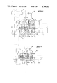
- FIGS. 1 to 11 are views in axial section of the device according to the invention and illustrate various operating stages of this device;
- FIGS. 1 to 4 show the successive steps allowing the device to change from the locked condition to the unlocked condition whereas FIGS. 5 to 7 show the change from the unlocked state to the locked state;
- FIGS. 8 and 9 illustrate the operation of the device in case of the bolt becoming jammed within the keeper.
- FIGS. 10 and 11 illustrate the operation of the device in case of a misalignment of the bolt with the keeper.
- FIG. 1 should alone be referred to for the purpose of describing the structure of the device according to the present invention and shown as a magnified view.
- This device essentially comprises a bolt 1 slidably mounted within a body or casing 2 and likely to co-operate with a notch 3 forming a keeper provided in any member such for instance as a bar 4 carrying bolts 5 allowing through operation of the bar 4 the door of a safe or strong-box for instance to be locked or unlocked.
- the body 2 comprises at one of its ends an opening 6 allowing the bolt 1 to extend therethrough and is closed at its other end by a removable end wall portion 7.
- the bolt 1 consists of a sleeve-like rear part 8 and of a front part 9 likely to co-operate with the keeper 3 and mounted in relatively movable relationship with respect to the rear part 8.
- the rear part 8 and the front part 9 of the bolt 1 are slidably mounted within the body 2.
- the front part 9 of the bolt 1 consists of a hollow element 10 in which is slidably arranged a rod 11 provided at its free end with a stop 12 which is slidable within the bore 10a of the hollow element 10.
- a first spring R 1 surrounding the rod 11 and accommodated inside of the bore 10a abuts on the one hand the stop 12 and, on the other hand, the rear portion 10b of the element 10 through which the rod 11 extends.
- the spring R 1 constantly urges the hollow element 10 to bear against the stop 12 of the rod 11.
- the rear portion 10b of the hollow element 10 would normally be in bearing engagement with the rear part 8 of the bolt 1.
- the rear part 8 of the bolt 1 assumes somewhat the shape of a sleeve and comprises two outer spaced annular grooves 15 and 16. Both grooves 15 and 16 may co-operate with the core 17 of a second electromagnet 18 fastened on the side of the body 2 through the medium of a lug 19 for instance.
- the grooves 15 and 16 of the rear part 8 could of course consist of recesses of any shapes likely to co-operate with the core 17 of the second electromagnet 18 and this without leaving the scope of the invention.
- the body 1 comprises an axial cavity 22 in which the bolt 1 is slidable.
- a shoulder formed within the cavity 22 and which limits the forward stroke of the rear part 8 of the bolt 1 under the action of the compression of the second spring R 2 .
- the heel 8a of the part 8 is abutting the shoulder 23 involved thereby corresponding to the inserted position of the front part 9 of the bolt 1 into the notch 3 of the bar 4.
- the bar 4 is locked by the front portion or part 9 of the bolt 1.
- the front part 9 is prevented from moving out of the keeper 3 by the presence of the rear part 8 the groove 16 of which receives the core 17 of the electromagnet 18. In that position, the system is at rest and the electromagnets 13 and 18 are not energized.
- the electromagnet 13 While keeping the electromagnet 18 energized, the electromagnet 13 is then energized thereby causing the rod 11 forming the core of the electromagnet 13 to move backwards as seen on FIG. 3. Then the system consisting of the rear part 8 and of the front part 9 both constituting the bolt 1 is displaced until the heel 8a of the part 8 is engaging or abutting the end wall portion 7 of the body 2. In this position seen on FIG. 3, the front portion 9 of the bolt 1 is withdrawn or retracted from the keeper 3 and the spring R 2 is compressed.
- the energizing of the electromagnet 13 is maintained and the energizing of the electromagnet 18 is switched out or discontinued. Then, the return spring R 3 biassing the core 17 of the electromagnet 18 causes this core to move downwards into the groove 15 of the rear part 8 of the bolt 1.
- the bar 4 is thus unlocked and the bolt 1 is locked within the body 2 as well seen on FIG. 4. Under these circumstances, it is possible to switch out or discontinue the supply of the electromagnet 13 with electric current. In other words, the bolt 1 is locked in the retracted position within the body 2 and the bar 4 may move freely.
- FIGS. 8 and 9 for briefly explaining the operation of the device in case of the front part 9 of the bolt 1 becoming jammed within the notch 3 of the bar 4.
- FIG. 8 This state is illustrated on FIG. 8 where it is seen that the wall of the notch 3 of the bar 4 is bearing upon the front portion 9 of the bolt 1.
- the sequence of the operating steps described with reference to FIGS. 2 to 4 is carried out.
- the condition shown on FIG. 9 corresponds to that shown on FIG. 4 but in this instance, the front portion 9 of the bolt has been left in the initial position jammed within the keeper 3, the spring R 1 being compressed and the free end of the element 10 being remote or spaced away from the stop 12 as well seen on FIG. 9.
- this element will automatically assume again its position retracted into the body 2 under the effect of the spring R 1 which will release itself. The arrangement will therefore assume again the position seen on FIG. 4 wherein the bar 4 has been unlocked.
- FIGS. 10 and 11 explain the operation of the device in case of a misalignment of the bolt 1 with the keeper 3 as well seen on FIG. 10 wherein it is seen that the bar 4 is wrongly positioned with respect to the front portion 9 of the bolt 1.
- the locking cycle may be carried out as explained with reference to FIGS. 5 to 7 but, in this instance, as seen on FIG. 11, the element 10 of the bolt is not engaging the notch 3 of the bar 4 and is caused to abut against this bar while being squeezed by the spring R 2 . It is seen here that the core 17 of the electromagnet 18 is bearing upon the rear part 8 of the bolt 1 between both grooves 15 and 16. Once the bar 4 is in adequate position, i.e. the notch 3 will be in front of or in registering relationship with the element 10, this element will move into the notch under the effect of the compression of the spring R 2 and the locking of the bolt 1 will be achieved by the core 17 of the electromagnet 18 moving into the groove 16 of the rear part 8 of the bolt 1. The appliance will therefore be again in the state seen on FIG. 7.
- a locking and unlocking device which would consume just a minimal amount of electric current thereby allowing the bolt to be locked or held against motion in the locked and unlocked positions, respectively, and which removes the inconveniences resulting from a jamming and misalignment of the bolt with respect to the member to be locked.
- the invention on the contrary, comprises all the technical equivalents of the means described as well as their combinations if same are carried out according to its gist.
Abstract
A device for locking and unlocking any member, comprising a bolt slidably mounted within a body and having a rear part and a front part to co-operate with a notch provided in said member in which a first electromagnet operates with its core in the bolt, the rear part of which may co-operate with the core of a second electromagnet to hold the bolt against motion within the body in a locked position on the member or in an unlocked position.
Description
The present invention relates to a device for locking and unlocking any member such for instance as a bar carrying bolts likely to co-operate with keepers, bolt-clasps or like bolt-staples or latch-catches for locking a door for instance.
Systems operated by an electric current for controlling lock bolts are already known.
It has thus already been proposed to fit doors with an electric keeper co-operating with a conventional bolt or spring-bolt. More specifically, the keeper is fitted with a small movable shutter or retainer which would retract or move aside under the action of the electric current and would release or disengage the bolt accordingly.
This system suffers from drawbacks. At first it would consume a certain amount of electric energy to the extent where the shutter or retainer of the keeper has to be kept electrically energized for some time necessary to the unlocking. Moreover, the locking of the spring-bolt within the keeper is not positive since this spring-bolt is acted upon by a simple spring and may therefore be easily picked and withdrawn from the electric keeper.
There are also locking and unlocking systems comprising a conventional bolt slidably mounted within a body and operated by an electromagnet allowing this bolt to move into and out of a keeper. This system however also exhibits the same kind of inconveniences.
As a matter of fact, the bolt which may consist of the core of the electromagnet would generally result in an electromagnet construction which is oversized and which has to be acted upon for a long time by the electric current to allow the bolt to move out of the keeper, thereby requiring a relatively substantial consumption of electric power. Furthermore, like the electric keepers, there is no positive locking of the bolt in the locked position so that is possible by means of a tool to readily actuate this bolt forming the core of the electromagnet in order to move the same out of its keeper. Finally and in case of a technical hitch resulting for instance from the bolt becoming jammed within the keeper, thereby preventing its retraction or also from the misalignment of the bolt with the keeper whereby its insertion into the said keeper would be prevented, it is understandable that the electromagnet would be kept energized by the user for a very long time in an attempt to nevertheless carry out the locking or unlocking operation which could lead to the electromagnet being damaged or even being put out of working order.
The object of the present invention is to cope in particular with the above-mentioned drawbacks by provided a device which requires a very low consumption of electric current only and which in addition, ensures a positive locking of the bolt in the locking or unlocking position.
For that purpose, the object of the invention is a device for locking and unlocking any member and of the type comprising at least one bolt slidably mounted within a body or casing and actuated by an electromagnet allowing this bolt to co-operate or not with a keeper-like notch or the like formed in the said member, characterized in that it comprises a second electromagnet co-operating with the other or first electromagnet to act positively upon the bolt in order in particular to lock it within the body or casing when it is in a position corresponding to its position of insertion into the keeper or in a position corresponding to its position moved out of or retracted from the said keeper.
According to another characterizing feature of the invention, the bolt consists on theone hand of a rear part co-operating with the core of the second electromagnet and, on the other hand, of a front part likely to co-operate with the keeper and mounted in relatively movable relationship with respect to the rear part.
It should be pointed out that the rear part of the bolt comprises on its periphery two spaced annular recesses or grooves co-operating with the core of the second electromagnet.
According to still another characterizing feature of this invention, the front part of the bolt consists of a hollow element in which is slidable a rod carrying at its free end a stop for a first spring surrounding the rod and constantly urging the hollow element towards a position bearing against the stop, this rod being made fast with and extending through the rear part of the bolt and forming the core of the first electromagnet.
According to still a further characterizing feature of the device according to the invention, a second spring surrounds the aforesaid rod and is in bearing engagement with and between the rear part of the bolt and the end wall of the body or casing in which the bolt is slidable.
A third spring is also provided for constantly urging the core of the second electromagnet towards the rear part of the bolt.
According to still another characterizing feature of this invention, the first electromagnet is secured externally onto the body in coaxial relationship therewith whereas the second electromagnet is externally secured onto the body so that its core extends at right angles to the centre line axis of the body and through a bore formed within the said body and opening towards the rear part of the bolt.
It should be pointed out that both electromagnets are electrically connected so that they may be electrically energized and de-energized selectively in accordance with the sequence of operations to be performed in order in particular to release, operate and lock the bolt within the body.
The invention will be better understood and further objects, characterizing features, details and advantages thereof will appear more clearly as the following explanatory description proceeds with reference to the accompanying diagrammatic drawings illustrating by way of a non-limiting example only a presently preferred specific embodiment of the invention and wherein:
All the FIGS. 1 to 11 are views in axial section of the device according to the invention and illustrate various operating stages of this device;
More specifically, FIGS. 1 to 4 show the successive steps allowing the device to change from the locked condition to the unlocked condition whereas FIGS. 5 to 7 show the change from the unlocked state to the locked state;
FIGS. 8 and 9 illustrate the operation of the device in case of the bolt becoming jammed within the keeper; and
FIGS. 10 and 11 illustrate the operation of the device in case of a misalignment of the bolt with the keeper.
On all these Figures, the same elements which are designated by the same reference characters are shown in different positions, respectively. Therefore, FIG. 1 should alone be referred to for the purpose of describing the structure of the device according to the present invention and shown as a magnified view.
This device essentially comprises a bolt 1 slidably mounted within a body or casing 2 and likely to co-operate with a notch 3 forming a keeper provided in any member such for instance as a bar 4 carrying bolts 5 allowing through operation of the bar 4 the door of a safe or strong-box for instance to be locked or unlocked.
The body 2 comprises at one of its ends an opening 6 allowing the bolt 1 to extend therethrough and is closed at its other end by a removable end wall portion 7.
The bolt 1 consists of a sleeve-like rear part 8 and of a front part 9 likely to co-operate with the keeper 3 and mounted in relatively movable relationship with respect to the rear part 8. The rear part 8 and the front part 9 of the bolt 1 are slidably mounted within the body 2.
More specifically, the front part 9 of the bolt 1 consists of a hollow element 10 in which is slidably arranged a rod 11 provided at its free end with a stop 12 which is slidable within the bore 10a of the hollow element 10. A first spring R1 surrounding the rod 11 and accommodated inside of the bore 10a abuts on the one hand the stop 12 and, on the other hand, the rear portion 10b of the element 10 through which the rod 11 extends. Thus, as it is understandable, the spring R1 constantly urges the hollow element 10 to bear against the stop 12 of the rod 11. It should be noted that the rear portion 10b of the hollow element 10 would normally be in bearing engagement with the rear part 8 of the bolt 1.
The rod 11 is secured to and extends through this rear part 8 and forms the core of a first electromagnet 13 externally fastened onto the body 2 through the agency of a lug or the like 14 and in coaxial relation to the centre line axis X--X' of this body.
A second spring R2 surrounds the rod 11 and is bearing on the one hand, against the rear portion or heel 8a of the part 8 and, on the other hand, upon the end wall portion 7 of the body 2.
The rear part 8 of the bolt 1 assumes somewhat the shape of a sleeve and comprises two outer spaced annular grooves 15 and 16. Both grooves 15 and 16 may co-operate with the core 17 of a second electromagnet 18 fastened on the side of the body 2 through the medium of a lug 19 for instance.
A third spring R3 mounted about the core 17 is bearing on the one hand upon the body of the electromagnet 18 and, on the other hand, upon a ring or the like 20 integral or made fast with the core 17 and slidable within a bore 21 formed through the wall of the body 2 and opening towards the rear part 8 of the bolt 1. The bore 21 hence the core 17 of the electromagnet 18 extend in a direction orthogonal to the centre line axis X--X' of the body 2 and this centre line axis also is that one of the bolt 1 consisting of the rear part 8 and of the front part 9 which co-operates with the keeper 3.
The grooves 15 and 16 of the rear part 8 could of course consist of recesses of any shapes likely to co-operate with the core 17 of the second electromagnet 18 and this without leaving the scope of the invention.
The body 1 comprises an axial cavity 22 in which the bolt 1 is slidable. At 23 has been shown a shoulder formed within the cavity 22 and which limits the forward stroke of the rear part 8 of the bolt 1 under the action of the compression of the second spring R2. In effect, as it is well seen on FIG. 1, the heel 8a of the part 8 is abutting the shoulder 23 involved thereby corresponding to the inserted position of the front part 9 of the bolt 1 into the notch 3 of the bar 4.
Having thus described the structure of the device according to the invention, its operation will now be explained.
It should at first be started from the locking position shown on FIG. 1 to explain how the unlocking occurs with reference to FIGS. 2 to 4.
As seen on FIG. 1, the bar 4 is locked by the front portion or part 9 of the bolt 1. The front part 9 is prevented from moving out of the keeper 3 by the presence of the rear part 8 the groove 16 of which receives the core 17 of the electromagnet 18. In that position, the system is at rest and the electromagnets 13 and 18 are not energized.
Through energizing of the electromagnet 18 and as well seen on FIG. 2, the core 17 is lifted against the force of the spring R3 which is compressed. The rear part or sleeve 8 of the bolt 1 is thus set free or disengaged.
While keeping the electromagnet 18 energized, the electromagnet 13 is then energized thereby causing the rod 11 forming the core of the electromagnet 13 to move backwards as seen on FIG. 3. Then the system consisting of the rear part 8 and of the front part 9 both constituting the bolt 1 is displaced until the heel 8a of the part 8 is engaging or abutting the end wall portion 7 of the body 2. In this position seen on FIG. 3, the front portion 9 of the bolt 1 is withdrawn or retracted from the keeper 3 and the spring R2 is compressed.
The energizing of the electromagnet 13 is maintained and the energizing of the electromagnet 18 is switched out or discontinued. Then, the return spring R3 biassing the core 17 of the electromagnet 18 causes this core to move downwards into the groove 15 of the rear part 8 of the bolt 1. The bar 4 is thus unlocked and the bolt 1 is locked within the body 2 as well seen on FIG. 4. Under these circumstances, it is possible to switch out or discontinue the supply of the electromagnet 13 with electric current. In other words, the bolt 1 is locked in the retracted position within the body 2 and the bar 4 may move freely.
It should now be started from the position seen on FIG. 4 to explain the operation of the system when effecting the locking and this with reference in particular to FIGS. 5, 6 and 7.
The electromagnets 13 and 18 are energized simultaneously thereby causing the core 17 of the electromagnet 18 to move out of the groove 15 of the rear part 8 as seen on FIG. 5. It should be pointed out that the spring R2 is compressed as well besides as the spring R3 .
Then, as seen on FIG. 6, the energizing of the electromagnet 13 is discontinued or switched out so that the spring R2 is released and induces the leftward displacement of the rod 11 hence of the part 8-part 9 system constituting the bolt 1 which therefore engages the notch or keeper 3 of the bar 4. It should be pointed out that the stroke of the part 8 of the bolt 1 is stopped through abutment of the heel 8a of the part 8 against the shoulder 23 of the body 2.
At last, the energizing of the electromagnet 18 is discontinued and the core 17 is returned by the spring R3 to the lower indexing position within the groove 16 of the part 8. Thus, the same condition as the one shown on FIG. 1 is restored or assumed again wherein the bolt 1 is locked thereby providing a positive locking of the bar 4. This means that any action by means of any tool upon the bolt 1 would be without any effect.
Reference should now be had to FIGS. 8 and 9 for briefly explaining the operation of the device in case of the front part 9 of the bolt 1 becoming jammed within the notch 3 of the bar 4.
This state is illustrated on FIG. 8 where it is seen that the wall of the notch 3 of the bar 4 is bearing upon the front portion 9 of the bolt 1.
For performing the unlocking, the sequence of the operating steps described with reference to FIGS. 2 to 4 is carried out. In other terms, the condition shown on FIG. 9 corresponds to that shown on FIG. 4 but in this instance, the front portion 9 of the bolt has been left in the initial position jammed within the keeper 3, the spring R1 being compressed and the free end of the element 10 being remote or spaced away from the stop 12 as well seen on FIG. 9. As soon as an action upon the bar 4 is effected to release the pressure of this bar upon the element 10, this element will automatically assume again its position retracted into the body 2 under the effect of the spring R1 which will release itself. The arrangement will therefore assume again the position seen on FIG. 4 wherein the bar 4 has been unlocked.
Reference should now be made to FIGS. 10 and 11 to explain the operation of the device in case of a misalignment of the bolt 1 with the keeper 3 as well seen on FIG. 10 wherein it is seen that the bar 4 is wrongly positioned with respect to the front portion 9 of the bolt 1.
The locking cycle may be carried out as explained with reference to FIGS. 5 to 7 but, in this instance, as seen on FIG. 11, the element 10 of the bolt is not engaging the notch 3 of the bar 4 and is caused to abut against this bar while being squeezed by the spring R2. It is seen here that the core 17 of the electromagnet 18 is bearing upon the rear part 8 of the bolt 1 between both grooves 15 and 16. Once the bar 4 is in adequate position, i.e. the notch 3 will be in front of or in registering relationship with the element 10, this element will move into the notch under the effect of the compression of the spring R2 and the locking of the bolt 1 will be achieved by the core 17 of the electromagnet 18 moving into the groove 16 of the rear part 8 of the bolt 1. The appliance will therefore be again in the state seen on FIG. 7.
There has thus been provided according to the invention, a locking and unlocking device which would consume just a minimal amount of electric current thereby allowing the bolt to be locked or held against motion in the locked and unlocked positions, respectively, and which removes the inconveniences resulting from a jamming and misalignment of the bolt with respect to the member to be locked.
This invention is of course not at all limited to the embodiment described and shown which has been given by way of example only.
The invention, on the contrary, comprises all the technical equivalents of the means described as well as their combinations if same are carried out according to its gist.
Claims (4)
1. A device for locking or unlocking a member, comprising:
a bolt (1) slidably mounted within a body (2) and actuated by a first electromagnet (13) allowing said bolt to co-operate with a notch or keeper (3) provided within a member;
a second electromagnet (18) acting upon said bolt in order to block said bolt within said body when said bolt is in an inserted or non-inserted position within said keeper (3);
said bolt (1) comprising a rear part (8) having on its periphery two spaced annular grooves (15, 16) whereas said second electromagnet (18) includes one core (17) co-operating with said grooves to block said bolt in said inserted or non-inserted position, respectively;
said bolt (1) comprises a bored hollow forward end (10) adapted to co-operate with said keeper (3) and movably mounted within said body (2) with respect to said rear part (8) whereas said first electromagnet (13) includes one core or rod (11) secured to and extending through the rear part (8) of the bolt and having a free end adapted to slide within said hollow forward end (10); and
said free end comprises a stop member (12) slidably mounted in the bore (10a) of said forward end (10), whereas a spring (R1) is provided in said bore around said rod (11) between said stop member (12) and a rear portion (10b) said forward end to constantly act upon the latter in a position bearing against said stop member;
whereby inconveniences resulting from jamming and misalignment of the bolt with respect to the member to be locked are eliminated.
2. A device according to claim 1, further comprising:
a second spring (R2) surrounding said rod (11), and
said body (2) includes an end wall portion (7) with said second spring bearing against the rear part (8) of the bolt and said end portion.
3. A device according to claim 2, further comprising:
a third spring (R3) urging the core (17) of said second electromagnet (18) towards the rear part (8) of the bolt.
4. A device according to claim 1, wherein both electromagnets (13, 18) are electrically connected so as to be selectively energizable or de-energizable: and
said first electromagnet (13) is externally secured onto said body (2) in coaxial relationship therewith, whereas said second electromagnet (18) is externally fastened onto said body so that its core (17) extends at a substantially right angle to a center line axis of said body and through a bore (21) provided in said body and opening towards the rear part (8) of the bolt.
Applications Claiming Priority (2)
| Application Number | Priority Date | Filing Date | Title |
|---|---|---|---|
| FR8602517 | 1986-02-24 | ||
| FR8602517A FR2594877B1 (en) | 1986-02-24 | 1986-02-24 | DEVICE FOR LOCKING AND UNLOCKING ANY BODY, SUCH AS FOR EXAMPLE A BAR HAVING PENES |
Publications (1)
| Publication Number | Publication Date |
|---|---|
| US4784415A true US4784415A (en) | 1988-11-15 |
Family
ID=9332459
Family Applications (1)
| Application Number | Title | Priority Date | Filing Date |
|---|---|---|---|
| US07/017,698 Expired - Fee Related US4784415A (en) | 1986-02-24 | 1987-02-24 | Locking and unlocking device |
Country Status (5)
| Country | Link |
|---|---|
| US (1) | US4784415A (en) |
| EP (1) | EP0235041B1 (en) |
| DE (1) | DE3760118D1 (en) |
| ES (1) | ES2008698B3 (en) |
| FR (1) | FR2594877B1 (en) |
Cited By (68)
| Publication number | Priority date | Publication date | Assignee | Title |
|---|---|---|---|---|
| US4936613A (en) * | 1987-10-02 | 1990-06-26 | Ferco International | Electrical blocking device for a fitting such as an espagnolette or espagnolette lock |
| US5027629A (en) * | 1990-01-22 | 1991-07-02 | Liu Yin Chic | Control mechanism of electronic lock |
| US5216909A (en) * | 1992-04-01 | 1993-06-08 | Armoogam Michael A | Electro-mechanical locking mechanism |
| US5219386A (en) * | 1988-05-06 | 1993-06-15 | Keba Gesellschaft M.B.H. & Co. | Locker unit comprising a plurality of lockers |
| US5228730A (en) * | 1992-09-02 | 1993-07-20 | Security People, Inc. | Apparatus for converting mechanical locks to operate electrically using momentary power |
| US5386713A (en) * | 1991-03-07 | 1995-02-07 | Wilson; Bert | Remote control car deadbolt lock |
| US5588318A (en) * | 1992-07-23 | 1996-12-31 | Fireking International, Inc. | Door lock |
| US5660065A (en) * | 1991-07-05 | 1997-08-26 | Icl Systems Ab | Portable computer locking device |
| WO1998033686A1 (en) * | 1997-02-04 | 1998-08-06 | Daimler-Benz Aktiengesellschaft | Electromagnetically actuated lock |
| US5845523A (en) * | 1994-03-30 | 1998-12-08 | U-Code, Inc. | Electronic input and dial entry lock |
| US6048000A (en) * | 1998-04-28 | 2000-04-11 | Geringer; Arthur | Delayed egress panic device with internal deadlocking bolt mechanism |
| US6112564A (en) * | 1995-12-20 | 2000-09-05 | Mannesmann Vdo Ag | Lock, in particular for motor vehicle doors |
| US6125671A (en) * | 1996-11-13 | 2000-10-03 | Kabushiki Kaisha Tokai Rika Denki Seisakusho | Steering lock system |
| US6282829B1 (en) | 1999-01-25 | 2001-09-04 | Jonathan E. Mossberg | Magnetic tag firearm safety enhancement system with grip switch |
| US6299222B1 (en) * | 1997-03-08 | 2001-10-09 | Emhart Inc. | Latchbolt |
| US6324878B1 (en) * | 1999-08-26 | 2001-12-04 | Methode Electronics, Inc. | Steering lock device with safety system |
| DE10041984A1 (en) * | 2000-08-26 | 2002-04-18 | Valeo Deutschland Gmbh & Co | Device for locking the steering spindle of a vehicle |
| US6499325B1 (en) * | 1999-02-19 | 2002-12-31 | Abloy Oy | Electromechanical actuator |
| US20030029266A1 (en) * | 2001-08-08 | 2003-02-13 | Gillingham James R. | Method and apparatus for providing for fail safe condition for an automatic security gate |
| US6549969B1 (en) * | 2000-02-29 | 2003-04-15 | International Business Machines Corporation | Interlock for preventing human error in hot pluggable systems |
| US6584817B1 (en) * | 2002-08-14 | 2003-07-01 | Wfe Technology Corp. | Electronic anti-theft lock |
| FR2839105A1 (en) * | 2002-04-25 | 2003-10-31 | Milivoye Zivanovic | Locking of door panels for utility vehicles with double doors, uses sleeves on both door panels with bolt passing through both to lock door, and head of bolt carrying a lock that secures it inside one sleeve |
| US6644072B1 (en) * | 2002-07-01 | 2003-11-11 | Hui-Hua Hsieh | Remote-controlled door lock |
| US6666054B1 (en) * | 2002-07-25 | 2003-12-23 | Hui-Hua Hsieh | Remote-controlled door lock |
| US6698263B2 (en) * | 2002-07-22 | 2004-03-02 | Hui-Hua Hsieh | Remote-controlled door lock |
| US20040066047A1 (en) * | 2001-02-09 | 2004-04-08 | Manfred Rockenbach | Device for securing a door leaf against unintentional deflection |
| US20040069024A1 (en) * | 2001-04-13 | 2004-04-15 | Saint-Gobain Pam | Device for mutually locking two elements, in particular a covering element to an element forming a support frame |
| US20040070214A1 (en) * | 2000-11-22 | 2004-04-15 | Gerard Queveau | Device for improving a vehicle structural rigidity, in particular a vehicle with retractable roof |
| US20040113436A1 (en) * | 2002-08-14 | 2004-06-17 | Ulrich Bantle | Coded lock II |
| US20050006908A1 (en) * | 2000-03-24 | 2005-01-13 | Azoteq (Pty) Ltd | Lock |
| US20050012343A1 (en) * | 2003-07-18 | 2005-01-20 | Mark Warden | Electronic door lock dogging mechanism |
| US20050104381A1 (en) * | 2002-09-30 | 2005-05-19 | Andrew Whitaker | Delayed egress exit device |
| US20050194797A1 (en) * | 2004-03-04 | 2005-09-08 | Radel Michael B. | Closure Latch Assembly |
| DE102004039531A1 (en) * | 2004-08-14 | 2006-02-23 | Aug. Winkhaus Gmbh & Co. Kg | locking mechanism |
| US20060118253A1 (en) * | 2004-12-03 | 2006-06-08 | Sargent Manufacturing Company | Low cost garage door lock |
| US20060201214A1 (en) * | 2001-10-22 | 2006-09-14 | Ulrich Bantle | Lock |
| US20060226672A1 (en) * | 2005-04-11 | 2006-10-12 | Ruhlander Gregory P | Tailgate lift-and-secure cable and latch assembly |
| US20070056338A1 (en) * | 2005-09-13 | 2007-03-15 | Eaton Corporation | Lock device and system employing a door lock device |
| US20070074550A1 (en) * | 2003-11-04 | 2007-04-05 | Ison Limited | Lock |
| US7296448B1 (en) * | 2001-02-22 | 2007-11-20 | Shaw Barry M | Electromagnetic integrative door locking device |
| US7469564B1 (en) * | 2004-02-26 | 2008-12-30 | Shaw Barry M | Second improved electromagnetic integrative door locking device and method of installation |
| US20090064733A1 (en) * | 2007-09-10 | 2009-03-12 | Pi-Chiu LIU | Lock core |
| US20090282879A1 (en) * | 2008-05-15 | 2009-11-19 | Master Lock Company Llc | Lock assembly with rotary locking member |
| US20100089104A1 (en) * | 2006-09-04 | 2010-04-15 | Michael John Watmough | Pneumatically operated barrier lock |
| US20100123323A1 (en) * | 2008-11-17 | 2010-05-20 | Security Door Controls | Electric latch retraction bar |
| US20100180511A1 (en) * | 2009-01-22 | 2010-07-22 | Pilz Auslandsbeteiligungen Gmbh | Locking device |
| DE10017482B4 (en) * | 1999-04-07 | 2010-12-30 | Trw Automotive Italia S.P.A. | Steering lock device for a vehicle steering assembly |
| US20110259060A1 (en) * | 2008-11-25 | 2011-10-27 | Tobias Leska | Safety switch for generating a system enable signal depending on the position of a movable guard door |
| US20120285207A1 (en) * | 2004-07-06 | 2012-11-15 | Homegate Ltd | Integrated security and emergency lock |
| US20120297842A1 (en) * | 2011-05-23 | 2012-11-29 | Gartner Klaus W | Electromechanical lock |
| DE102012017846A1 (en) * | 2012-09-08 | 2014-03-13 | Gantner Electronic Gmbh | Cabinet lock for multiple cabinet system, comprises displacement drive, which is hydraulically or pneumatically formed for operating locking mechanism of locking bar, and hydraulic or pneumatic drive elements for generating actuating energy |
| US20140124282A1 (en) * | 2011-01-21 | 2014-05-08 | Valeo Sicherheitssysteme Gmbh | Antitheft device for the steering mechanism of a motor vehicle |
| US20150028734A1 (en) * | 2012-02-13 | 2015-01-29 | Elbi International S.P.A. | Device for closing the door of a household appliance, in particular for a washing machine, such as a dishwasher |
| US20160160534A1 (en) * | 2014-12-04 | 2016-06-09 | Larry Buchanan | Door locking system |
| US20160333608A1 (en) * | 2015-05-15 | 2016-11-17 | Michael Earl Ingle | Anti-Bumping Impact Protection Device and Method for Solenoid-Operated Locking Containers |
| US20170297817A1 (en) * | 2013-01-25 | 2017-10-19 | Serio-Us Industries, Inc. | Container with automatic latch assembly |
| US10107015B2 (en) | 2008-11-17 | 2018-10-23 | Security Door Controls | Electric latch retraction push-bar device |
| US20190390480A1 (en) * | 2018-02-21 | 2019-12-26 | Axuator OY | Digital lock |
| WO2020206388A1 (en) * | 2019-04-05 | 2020-10-08 | Dormakaba Usa Inc. | Electronic lock |
| US10890014B2 (en) | 2018-02-21 | 2021-01-12 | Axtuator OY | Electromagnetic actuator |
| US20210054657A1 (en) * | 2019-08-22 | 2021-02-25 | Carrier Corporation | Latch assembly for vertical door |
| US20210180369A1 (en) * | 2019-12-16 | 2021-06-17 | GM Global Technology Operations LLC | Dynamic lock mechanism |
| CN113503096A (en) * | 2017-12-29 | 2021-10-15 | 上海电巴新能源科技有限公司 | Protection lock mechanism |
| US20210337679A1 (en) * | 2019-01-22 | 2021-10-28 | Core-Arms, LLC | Mounting System, Devices, Methods and Uses Thereof |
| DE102021109993B3 (en) | 2021-04-20 | 2022-09-01 | Pilz Gmbh & Co. Kg | Safety switch with guard locking |
| US20220333412A1 (en) * | 2019-12-12 | 2022-10-20 | Vitesco Technologies GmbH | Emergency access device for a vehicle opening panel with electrical ejector comprising a percussion mode |
| US11505967B2 (en) * | 2019-08-22 | 2022-11-22 | Janus International Group, Llc | Controllable door lock |
| US20230193666A1 (en) * | 2020-05-29 | 2023-06-22 | Vitesco Technologies GmbH | Emergency access device for vehicle opening panel having a retention lever and a pull wire |
Families Citing this family (4)
| Publication number | Priority date | Publication date | Assignee | Title |
|---|---|---|---|---|
| DE3804838C1 (en) * | 1988-02-17 | 1989-01-26 | Vdo Adolf Schindling Ag, 6000 Frankfurt, De | |
| DE3841573A1 (en) * | 1988-12-09 | 1990-06-13 | Verschlusstechnik Produktions | Lock |
| AT400608B (en) * | 1991-10-22 | 1996-02-26 | Wiener Metallwerk Gesmbh | LOCKING FOR DOORS, IN PARTICULAR HINGED DOORS |
| DE9413062U1 (en) * | 1994-08-12 | 1994-12-15 | Reiners Christa | bars |
Citations (16)
| Publication number | Priority date | Publication date | Assignee | Title |
|---|---|---|---|---|
| US188308A (en) * | 1877-03-13 | Improvement in combined latqh and bolt | ||
| GB190904863A (en) * | 1909-02-27 | 1909-06-24 | George Pringle Fairless | A Magnetic Locking Device for Locking Railway Carriage Doors, Safes or for other Purposes. |
| US966780A (en) * | 1908-03-27 | 1910-08-09 | Ernest K Thomas | Bolt. |
| GB191112941A (en) * | 1911-05-30 | 1912-03-21 | Joseph Thomas Russell | Improvements in Electrically Operated Fastenings for Railway Carriage and other Doors. |
| FR456440A (en) * | 1913-04-08 | 1913-08-26 | Heinrich Rodriguez Larreta | Electric door lock |
| GB144476A (en) * | 1919-06-16 | 1920-06-17 | Edward Joseph Pyke | An improved locking device for motor cars and similar vehicles |
| US1920080A (en) * | 1932-06-14 | 1933-07-25 | Jenkins Arthur Edward | Electrogravity lock |
| US1948217A (en) * | 1932-03-14 | 1934-02-20 | Sr Charles M Goodwin | Electric lock |
| US2178313A (en) * | 1937-04-29 | 1939-10-31 | Jr William Morris Rossiter | Latch |
| FR1041439A (en) * | 1951-08-30 | 1953-10-23 | Improvements to door locking devices on board automobiles | |
| US2765648A (en) * | 1953-03-13 | 1956-10-09 | Curtis M Hatcher | Electro-magnetic vehicle door lock |
| US3288524A (en) * | 1964-11-23 | 1966-11-29 | Edward L Gordon | Automobile door safety lock |
| GB1137760A (en) * | 1965-09-15 | 1968-12-27 | Siemens Ag | Combined external and internal locking systems |
| US4021065A (en) * | 1975-07-08 | 1977-05-03 | Geringer Arthur V | Electric lock |
| FR2534392A1 (en) * | 1982-10-08 | 1984-04-13 | Kompex | Electrical control method for locking systems producing an energy saving |
| US4501203A (en) * | 1981-06-30 | 1985-02-26 | A/S Sparevirke | Safety mechanism for preventing the locking up of persons in cabinets |
Family Cites Families (1)
| Publication number | Priority date | Publication date | Assignee | Title |
|---|---|---|---|---|
| GB190904836A (en) * | 1908-06-11 | 1909-05-06 | Worthworks Wall | Improvements in and relating to Trouser Presses. |
-
1986
- 1986-02-24 FR FR8602517A patent/FR2594877B1/en not_active Expired - Lifetime
-
1987
- 1987-02-23 DE DE8787400394T patent/DE3760118D1/en not_active Expired
- 1987-02-23 EP EP87400394A patent/EP0235041B1/en not_active Expired
- 1987-02-23 ES ES87400394T patent/ES2008698B3/en not_active Expired
- 1987-02-24 US US07/017,698 patent/US4784415A/en not_active Expired - Fee Related
Patent Citations (16)
| Publication number | Priority date | Publication date | Assignee | Title |
|---|---|---|---|---|
| US188308A (en) * | 1877-03-13 | Improvement in combined latqh and bolt | ||
| US966780A (en) * | 1908-03-27 | 1910-08-09 | Ernest K Thomas | Bolt. |
| GB190904863A (en) * | 1909-02-27 | 1909-06-24 | George Pringle Fairless | A Magnetic Locking Device for Locking Railway Carriage Doors, Safes or for other Purposes. |
| GB191112941A (en) * | 1911-05-30 | 1912-03-21 | Joseph Thomas Russell | Improvements in Electrically Operated Fastenings for Railway Carriage and other Doors. |
| FR456440A (en) * | 1913-04-08 | 1913-08-26 | Heinrich Rodriguez Larreta | Electric door lock |
| GB144476A (en) * | 1919-06-16 | 1920-06-17 | Edward Joseph Pyke | An improved locking device for motor cars and similar vehicles |
| US1948217A (en) * | 1932-03-14 | 1934-02-20 | Sr Charles M Goodwin | Electric lock |
| US1920080A (en) * | 1932-06-14 | 1933-07-25 | Jenkins Arthur Edward | Electrogravity lock |
| US2178313A (en) * | 1937-04-29 | 1939-10-31 | Jr William Morris Rossiter | Latch |
| FR1041439A (en) * | 1951-08-30 | 1953-10-23 | Improvements to door locking devices on board automobiles | |
| US2765648A (en) * | 1953-03-13 | 1956-10-09 | Curtis M Hatcher | Electro-magnetic vehicle door lock |
| US3288524A (en) * | 1964-11-23 | 1966-11-29 | Edward L Gordon | Automobile door safety lock |
| GB1137760A (en) * | 1965-09-15 | 1968-12-27 | Siemens Ag | Combined external and internal locking systems |
| US4021065A (en) * | 1975-07-08 | 1977-05-03 | Geringer Arthur V | Electric lock |
| US4501203A (en) * | 1981-06-30 | 1985-02-26 | A/S Sparevirke | Safety mechanism for preventing the locking up of persons in cabinets |
| FR2534392A1 (en) * | 1982-10-08 | 1984-04-13 | Kompex | Electrical control method for locking systems producing an energy saving |
Cited By (113)
| Publication number | Priority date | Publication date | Assignee | Title |
|---|---|---|---|---|
| US4936613A (en) * | 1987-10-02 | 1990-06-26 | Ferco International | Electrical blocking device for a fitting such as an espagnolette or espagnolette lock |
| US5219386A (en) * | 1988-05-06 | 1993-06-15 | Keba Gesellschaft M.B.H. & Co. | Locker unit comprising a plurality of lockers |
| US5027629A (en) * | 1990-01-22 | 1991-07-02 | Liu Yin Chic | Control mechanism of electronic lock |
| US5386713A (en) * | 1991-03-07 | 1995-02-07 | Wilson; Bert | Remote control car deadbolt lock |
| US5660065A (en) * | 1991-07-05 | 1997-08-26 | Icl Systems Ab | Portable computer locking device |
| US5216909A (en) * | 1992-04-01 | 1993-06-08 | Armoogam Michael A | Electro-mechanical locking mechanism |
| US5588318A (en) * | 1992-07-23 | 1996-12-31 | Fireking International, Inc. | Door lock |
| US5228730A (en) * | 1992-09-02 | 1993-07-20 | Security People, Inc. | Apparatus for converting mechanical locks to operate electrically using momentary power |
| US5845523A (en) * | 1994-03-30 | 1998-12-08 | U-Code, Inc. | Electronic input and dial entry lock |
| US6112564A (en) * | 1995-12-20 | 2000-09-05 | Mannesmann Vdo Ag | Lock, in particular for motor vehicle doors |
| US6295848B1 (en) | 1996-11-13 | 2001-10-02 | Siemens Westinghouse Power Corporation | Steering lock system |
| US6125671A (en) * | 1996-11-13 | 2000-10-03 | Kabushiki Kaisha Tokai Rika Denki Seisakusho | Steering lock system |
| US6035675A (en) * | 1997-02-04 | 2000-03-14 | Daimler Benz Aktiengesellschaft | Electromagnetically actuated lock |
| DE19704062C2 (en) * | 1997-02-04 | 1999-01-28 | Daimler Benz Ag | Electromagnetically operated lock |
| DE19704062A1 (en) * | 1997-02-04 | 1998-08-13 | Daimler Benz Ag | Electromagnetically operated lock |
| WO1998033686A1 (en) * | 1997-02-04 | 1998-08-06 | Daimler-Benz Aktiengesellschaft | Electromagnetically actuated lock |
| US6299222B1 (en) * | 1997-03-08 | 2001-10-09 | Emhart Inc. | Latchbolt |
| US6048000A (en) * | 1998-04-28 | 2000-04-11 | Geringer; Arthur | Delayed egress panic device with internal deadlocking bolt mechanism |
| US6282829B1 (en) | 1999-01-25 | 2001-09-04 | Jonathan E. Mossberg | Magnetic tag firearm safety enhancement system with grip switch |
| US6343429B1 (en) | 1999-01-25 | 2002-02-05 | Mossberg Group, L.L.C. | Inertia-resistant preventer mechanism for firearm safety enhancement system |
| US6499325B1 (en) * | 1999-02-19 | 2002-12-31 | Abloy Oy | Electromechanical actuator |
| DE10017482B4 (en) * | 1999-04-07 | 2010-12-30 | Trw Automotive Italia S.P.A. | Steering lock device for a vehicle steering assembly |
| US6324878B1 (en) * | 1999-08-26 | 2001-12-04 | Methode Electronics, Inc. | Steering lock device with safety system |
| US6549969B1 (en) * | 2000-02-29 | 2003-04-15 | International Business Machines Corporation | Interlock for preventing human error in hot pluggable systems |
| US20050006908A1 (en) * | 2000-03-24 | 2005-01-13 | Azoteq (Pty) Ltd | Lock |
| US6439011B1 (en) | 2000-08-26 | 2002-08-27 | Valeo Deutschland Gmbh & Co. Sicherheitssysteme | Device for locking the steering spindle of a vehicle |
| DE10041984B4 (en) * | 2000-08-26 | 2006-02-23 | Valeo Sicherheitssysteme Gmbh | Device for locking the steering spindle of a vehicle |
| DE10041984A1 (en) * | 2000-08-26 | 2002-04-18 | Valeo Deutschland Gmbh & Co | Device for locking the steering spindle of a vehicle |
| US20040070214A1 (en) * | 2000-11-22 | 2004-04-15 | Gerard Queveau | Device for improving a vehicle structural rigidity, in particular a vehicle with retractable roof |
| US7165792B2 (en) * | 2000-11-22 | 2007-01-23 | Seba - Societe Europeenne De Brevets Automobiles | Device for improving a vehicle structural rigidity, in particular a vehicle with retractable roof |
| US6959949B2 (en) * | 2001-02-09 | 2005-11-01 | Dorma Gmbh + Co. Kg | Device for securing a door leaf against unintentional deflection |
| US20040066047A1 (en) * | 2001-02-09 | 2004-04-08 | Manfred Rockenbach | Device for securing a door leaf against unintentional deflection |
| US7296448B1 (en) * | 2001-02-22 | 2007-11-20 | Shaw Barry M | Electromagnetic integrative door locking device |
| US6735992B2 (en) * | 2001-04-13 | 2004-05-18 | Saint-Gobain Pam Crd | Device for mutually locking two elements, in particular a covering element to an element forming a support frame |
| US20040069024A1 (en) * | 2001-04-13 | 2004-04-15 | Saint-Gobain Pam | Device for mutually locking two elements, in particular a covering element to an element forming a support frame |
| US20030029266A1 (en) * | 2001-08-08 | 2003-02-13 | Gillingham James R. | Method and apparatus for providing for fail safe condition for an automatic security gate |
| US7144051B2 (en) * | 2001-08-08 | 2006-12-05 | The Chamberlain Group, Inc. | Method and apparatus for providing for fail safe condition for an automatic security gate |
| US20060201214A1 (en) * | 2001-10-22 | 2006-09-14 | Ulrich Bantle | Lock |
| FR2839105A1 (en) * | 2002-04-25 | 2003-10-31 | Milivoye Zivanovic | Locking of door panels for utility vehicles with double doors, uses sleeves on both door panels with bolt passing through both to lock door, and head of bolt carrying a lock that secures it inside one sleeve |
| US6644072B1 (en) * | 2002-07-01 | 2003-11-11 | Hui-Hua Hsieh | Remote-controlled door lock |
| US6698263B2 (en) * | 2002-07-22 | 2004-03-02 | Hui-Hua Hsieh | Remote-controlled door lock |
| US6666054B1 (en) * | 2002-07-25 | 2003-12-23 | Hui-Hua Hsieh | Remote-controlled door lock |
| US6584817B1 (en) * | 2002-08-14 | 2003-07-01 | Wfe Technology Corp. | Electronic anti-theft lock |
| US20040113436A1 (en) * | 2002-08-14 | 2004-06-17 | Ulrich Bantle | Coded lock II |
| US20090079204A1 (en) * | 2002-09-30 | 2009-03-26 | Yale Security Inc. | Delayed egress exit device |
| US7832778B2 (en) * | 2002-09-30 | 2010-11-16 | Yale Security Inc. | Delayed egress exit device |
| US20050104381A1 (en) * | 2002-09-30 | 2005-05-19 | Andrew Whitaker | Delayed egress exit device |
| US7469942B2 (en) * | 2002-09-30 | 2008-12-30 | Yale Security Inc. | Delayed egress exit device |
| US7055871B2 (en) | 2003-07-18 | 2006-06-06 | Jackson Corp. | Electronic door lock dogging mechanism |
| US20050012343A1 (en) * | 2003-07-18 | 2005-01-20 | Mark Warden | Electronic door lock dogging mechanism |
| US20070074550A1 (en) * | 2003-11-04 | 2007-04-05 | Ison Limited | Lock |
| US7469564B1 (en) * | 2004-02-26 | 2008-12-30 | Shaw Barry M | Second improved electromagnetic integrative door locking device and method of installation |
| US7044509B2 (en) * | 2004-03-04 | 2006-05-16 | Radel Michael B | Closure latch assembly |
| US20050194797A1 (en) * | 2004-03-04 | 2005-09-08 | Radel Michael B. | Closure Latch Assembly |
| US20120285207A1 (en) * | 2004-07-06 | 2012-11-15 | Homegate Ltd | Integrated security and emergency lock |
| US9068381B2 (en) * | 2004-07-06 | 2015-06-30 | Erez Segev | Integrated security and emergency lock |
| DE102004039531A1 (en) * | 2004-08-14 | 2006-02-23 | Aug. Winkhaus Gmbh & Co. Kg | locking mechanism |
| US8596330B2 (en) * | 2004-12-03 | 2013-12-03 | Sargent Manufacturing Company | Low cost garage door lock |
| US20060118253A1 (en) * | 2004-12-03 | 2006-06-08 | Sargent Manufacturing Company | Low cost garage door lock |
| US7281748B2 (en) * | 2005-04-11 | 2007-10-16 | Dura Global Technologies, Inc. | Tailgate lift-and-secure cable and latch assembly |
| US20060226672A1 (en) * | 2005-04-11 | 2006-10-12 | Ruhlander Gregory P | Tailgate lift-and-secure cable and latch assembly |
| US20070056338A1 (en) * | 2005-09-13 | 2007-03-15 | Eaton Corporation | Lock device and system employing a door lock device |
| US7520152B2 (en) * | 2005-09-13 | 2009-04-21 | Eaton Corporation | Lock device and system employing a door lock device |
| US20100089104A1 (en) * | 2006-09-04 | 2010-04-15 | Michael John Watmough | Pneumatically operated barrier lock |
| US20090064733A1 (en) * | 2007-09-10 | 2009-03-12 | Pi-Chiu LIU | Lock core |
| US20090282879A1 (en) * | 2008-05-15 | 2009-11-19 | Master Lock Company Llc | Lock assembly with rotary locking member |
| CN102027178A (en) * | 2008-07-15 | 2011-04-20 | 总锁有限责任公司 | Lock assembly with rotary locking member |
| US20100123323A1 (en) * | 2008-11-17 | 2010-05-20 | Security Door Controls | Electric latch retraction bar |
| US9797165B2 (en) | 2008-11-17 | 2017-10-24 | Security Door Controls | Electric latch retraction bar |
| US8851530B2 (en) | 2008-11-17 | 2014-10-07 | 1 Adolfo, Llc | Electric latch retraction bar |
| US10107015B2 (en) | 2008-11-17 | 2018-10-23 | Security Door Controls | Electric latch retraction push-bar device |
| US20110259060A1 (en) * | 2008-11-25 | 2011-10-27 | Tobias Leska | Safety switch for generating a system enable signal depending on the position of a movable guard door |
| US8814233B2 (en) * | 2008-11-25 | 2014-08-26 | Pilz Gmbh & Co. Kg | Safety switch for generating a system enable signal depending on the position of a movable guard door |
| US8272169B2 (en) * | 2009-01-22 | 2012-09-25 | Pilz Auslandsbetbiligungen GmbH | Locking device |
| US20100180511A1 (en) * | 2009-01-22 | 2010-07-22 | Pilz Auslandsbeteiligungen Gmbh | Locking device |
| US20140124282A1 (en) * | 2011-01-21 | 2014-05-08 | Valeo Sicherheitssysteme Gmbh | Antitheft device for the steering mechanism of a motor vehicle |
| US8978811B2 (en) * | 2011-01-21 | 2015-03-17 | Valeo Sicherheitssysteme Gmbh | Antitheft device for the steering mechanism of a motor vehicle |
| US8495899B2 (en) * | 2011-05-23 | 2013-07-30 | Klaus W. Gartner | Electromechanical lock |
| US20120297842A1 (en) * | 2011-05-23 | 2012-11-29 | Gartner Klaus W | Electromechanical lock |
| US20150028734A1 (en) * | 2012-02-13 | 2015-01-29 | Elbi International S.P.A. | Device for closing the door of a household appliance, in particular for a washing machine, such as a dishwasher |
| US9580952B2 (en) * | 2012-02-13 | 2017-02-28 | Elbi International S.P.A. | Device for closing the door of a household appliance, in particular for a washing machine, such as a dishwasher |
| DE102012017846B4 (en) * | 2012-09-08 | 2016-02-25 | Gantner Electronic Gmbh | Hydraulic and pneumatic locking mechanism for cabinet locks |
| DE102012017846A1 (en) * | 2012-09-08 | 2014-03-13 | Gantner Electronic Gmbh | Cabinet lock for multiple cabinet system, comprises displacement drive, which is hydraulically or pneumatically formed for operating locking mechanism of locking bar, and hydraulic or pneumatic drive elements for generating actuating energy |
| US20170297817A1 (en) * | 2013-01-25 | 2017-10-19 | Serio-Us Industries, Inc. | Container with automatic latch assembly |
| US20160160534A1 (en) * | 2014-12-04 | 2016-06-09 | Larry Buchanan | Door locking system |
| US9874045B2 (en) * | 2014-12-04 | 2018-01-23 | Larry Buchanan | Door locking system |
| US20160333608A1 (en) * | 2015-05-15 | 2016-11-17 | Michael Earl Ingle | Anti-Bumping Impact Protection Device and Method for Solenoid-Operated Locking Containers |
| CN113503096B (en) * | 2017-12-29 | 2022-05-06 | 上海电巴新能源科技有限公司 | Protection lock mechanism |
| CN113503096A (en) * | 2017-12-29 | 2021-10-15 | 上海电巴新能源科技有限公司 | Protection lock mechanism |
| US11933073B2 (en) | 2018-02-21 | 2024-03-19 | Iloq Oy | Digital lock |
| US10890014B2 (en) | 2018-02-21 | 2021-01-12 | Axtuator OY | Electromagnetic actuator |
| US11619069B2 (en) | 2018-02-21 | 2023-04-04 | Iloq Oy | Electromagnetic actuator |
| US11566446B2 (en) | 2018-02-21 | 2023-01-31 | Iloq Oy | Digital lock |
| US10844632B2 (en) * | 2018-02-21 | 2020-11-24 | Axtuator OY | Digital lock |
| US20190390480A1 (en) * | 2018-02-21 | 2019-12-26 | Axuator OY | Digital lock |
| US20210337679A1 (en) * | 2019-01-22 | 2021-10-28 | Core-Arms, LLC | Mounting System, Devices, Methods and Uses Thereof |
| CN113631786A (en) * | 2019-04-05 | 2021-11-09 | 多玛卡巴美国公司 | Electronic lock |
| AU2020253566B2 (en) * | 2019-04-05 | 2023-07-20 | Dormakaba Usa Inc. | Electronic lock |
| WO2020206388A1 (en) * | 2019-04-05 | 2020-10-08 | Dormakaba Usa Inc. | Electronic lock |
| US11920378B2 (en) | 2019-04-05 | 2024-03-05 | dormakaba USA, Inc | Electronic lock |
| US11879271B2 (en) | 2019-08-22 | 2024-01-23 | Janus International Group, Llc | Controllable door lock |
| US20210054658A1 (en) * | 2019-08-22 | 2021-02-25 | Carrier Corporation | Latch assembly for vertical door and method of operating |
| US20210054657A1 (en) * | 2019-08-22 | 2021-02-25 | Carrier Corporation | Latch assembly for vertical door |
| US11505967B2 (en) * | 2019-08-22 | 2022-11-22 | Janus International Group, Llc | Controllable door lock |
| US11846120B2 (en) | 2019-08-22 | 2023-12-19 | Carrier Corporation | Latch assembly with removable battery |
| US11859410B2 (en) * | 2019-08-22 | 2024-01-02 | Carrier Corporation | Latch assembly for vertical door |
| US11946286B2 (en) * | 2019-08-22 | 2024-04-02 | Carrier Corporation | Latch assembly for vertical door and method of operating |
| US11773630B2 (en) * | 2019-12-12 | 2023-10-03 | Vitesco Technologies GmbH | Emergency access device for a vehicle opening panel with electrical ejector comprising a percussion mode |
| US20220333412A1 (en) * | 2019-12-12 | 2022-10-20 | Vitesco Technologies GmbH | Emergency access device for a vehicle opening panel with electrical ejector comprising a percussion mode |
| US20210180369A1 (en) * | 2019-12-16 | 2021-06-17 | GM Global Technology Operations LLC | Dynamic lock mechanism |
| US20230193666A1 (en) * | 2020-05-29 | 2023-06-22 | Vitesco Technologies GmbH | Emergency access device for vehicle opening panel having a retention lever and a pull wire |
| US11814880B2 (en) * | 2020-05-29 | 2023-11-14 | Vitesco Technologies GmbH | Emergency access device for vehicle opening panel having a retention lever and a pull wire |
| DE102021109993B3 (en) | 2021-04-20 | 2022-09-01 | Pilz Gmbh & Co. Kg | Safety switch with guard locking |
Also Published As
| Publication number | Publication date |
|---|---|
| DE3760118D1 (en) | 1989-06-01 |
| FR2594877B1 (en) | 1991-06-21 |
| EP0235041B1 (en) | 1989-04-26 |
| ES2008698B3 (en) | 1989-08-01 |
| EP0235041A1 (en) | 1987-09-02 |
| FR2594877A1 (en) | 1987-08-28 |
Similar Documents
| Publication | Publication Date | Title |
|---|---|---|
| US4784415A (en) | Locking and unlocking device | |
| US5061112A (en) | Method and apparatus for releasably connecting first and second objects | |
| US4071271A (en) | Automatic release and ejection locking mechanism | |
| US2987334A (en) | Tool holders | |
| US7121126B2 (en) | Apparatus for locking a motor-vehicle steering shaft | |
| CA2147409C (en) | Quick coupling for pressure conduit with controlled disengagement | |
| US7410038B2 (en) | Locking unit | |
| US4537100A (en) | Push-on/quick release locking arrangement for socket wrench extension | |
| CA2120194C (en) | Cylinder lock device resistible against unauthorized unlocking | |
| US6298938B1 (en) | Locking device for the steering system of motor vehicles | |
| US5775147A (en) | Locking device, especially for motor vehicle locking | |
| EP0588209A1 (en) | Lock with electric activation | |
| US2708589A (en) | Tension actuated pipe coupling | |
| JP2002125979A (en) | Sleeve shape device for holding screw in the case of driving screw onto object such as bone by screwdriver | |
| JPS62228631A (en) | Manual type working mechanism for emergency for solenoid | |
| CN115279972A (en) | Quick coupler | |
| US5263751A (en) | Door latch actuator | |
| US4099395A (en) | Tumbler pin-type cylinder lock | |
| GB1335904A (en) | Key operated lock | |
| US5087090A (en) | Combination lockout/holdback apparatus | |
| US3437370A (en) | Release mechanisms | |
| WO2001057382A3 (en) | Locking device for a thrust reverser | |
| JPS61252921A (en) | Clutch release mechanism | |
| EP2436856A1 (en) | Bolt mechanism | |
| US6293489B1 (en) | Lock for a trust reverser |
Legal Events
| Date | Code | Title | Description |
|---|---|---|---|
| AS | Assignment |
Owner name: FICHET-BAUCHE, 15-17 AVENUE MORANE SAULNIER, 78141 Free format text: ASSIGNMENT OF ASSIGNORS INTEREST.;ASSIGNOR:MALAVAL, JEAN L. P. A.;REEL/FRAME:004694/0941 Effective date: 19870219 |
|
| FEPP | Fee payment procedure |
Free format text: PAYOR NUMBER ASSIGNED (ORIGINAL EVENT CODE: ASPN); ENTITY STATUS OF PATENT OWNER: LARGE ENTITY |
|
| FPAY | Fee payment |
Year of fee payment: 4 |
|
| REMI | Maintenance fee reminder mailed | ||
| LAPS | Lapse for failure to pay maintenance fees | ||
| FP | Lapsed due to failure to pay maintenance fee |
Effective date: 19961120 |
|
| STCH | Information on status: patent discontinuation |
Free format text: PATENT EXPIRED DUE TO NONPAYMENT OF MAINTENANCE FEES UNDER 37 CFR 1.362 |