US4788694A - Trellis coding with substrates - Google Patents
Trellis coding with substrates Download PDFInfo
- Publication number
- US4788694A US4788694A US07/017,894 US1789487A US4788694A US 4788694 A US4788694 A US 4788694A US 1789487 A US1789487 A US 1789487A US 4788694 A US4788694 A US 4788694A
- Authority
- US
- United States
- Prior art keywords
- channel
- seed
- signal
- bits
- point
- Prior art date
- Legal status (The legal status is an assumption and is not a legal conclusion. Google has not performed a legal analysis and makes no representation as to the accuracy of the status listed.)
- Expired - Lifetime
Links
Images


Classifications
-
- H—ELECTRICITY
- H03—ELECTRONIC CIRCUITRY
- H03M—CODING; DECODING; CODE CONVERSION IN GENERAL
- H03M13/00—Coding, decoding or code conversion, for error detection or error correction; Coding theory basic assumptions; Coding bounds; Error probability evaluation methods; Channel models; Simulation or testing of codes
- H03M13/03—Error detection or forward error correction by redundancy in data representation, i.e. code words containing more digits than the source words
- H03M13/23—Error detection or forward error correction by redundancy in data representation, i.e. code words containing more digits than the source words using convolutional codes, e.g. unit memory codes
-
- H—ELECTRICITY
- H04—ELECTRIC COMMUNICATION TECHNIQUE
- H04L—TRANSMISSION OF DIGITAL INFORMATION, e.g. TELEGRAPHIC COMMUNICATION
- H04L1/00—Arrangements for detecting or preventing errors in the information received
- H04L1/004—Arrangements for detecting or preventing errors in the information received by using forward error control
- H04L1/0045—Arrangements at the receiver end
- H04L1/0054—Maximum-likelihood or sequential decoding, e.g. Viterbi, Fano, ZJ algorithms
-
- H—ELECTRICITY
- H04—ELECTRIC COMMUNICATION TECHNIQUE
- H04L—TRANSMISSION OF DIGITAL INFORMATION, e.g. TELEGRAPHIC COMMUNICATION
- H04L25/00—Baseband systems
- H04L25/38—Synchronous or start-stop systems, e.g. for Baudot code
- H04L25/40—Transmitting circuits; Receiving circuits
- H04L25/49—Transmitting circuits; Receiving circuits using code conversion at the transmitter; using predistortion; using insertion of idle bits for obtaining a desired frequency spectrum; using three or more amplitude levels ; Baseband coding techniques specific to data transmission systems
- H04L25/4917—Transmitting circuits; Receiving circuits using code conversion at the transmitter; using predistortion; using insertion of idle bits for obtaining a desired frequency spectrum; using three or more amplitude levels ; Baseband coding techniques specific to data transmission systems using multilevel codes
-
- H—ELECTRICITY
- H04—ELECTRIC COMMUNICATION TECHNIQUE
- H04L—TRANSMISSION OF DIGITAL INFORMATION, e.g. TELEGRAPHIC COMMUNICATION
- H04L25/00—Baseband systems
- H04L25/38—Synchronous or start-stop systems, e.g. for Baudot code
- H04L25/40—Transmitting circuits; Receiving circuits
- H04L25/49—Transmitting circuits; Receiving circuits using code conversion at the transmitter; using predistortion; using insertion of idle bits for obtaining a desired frequency spectrum; using three or more amplitude levels ; Baseband coding techniques specific to data transmission systems
- H04L25/497—Transmitting circuits; Receiving circuits using code conversion at the transmitter; using predistortion; using insertion of idle bits for obtaining a desired frequency spectrum; using three or more amplitude levels ; Baseband coding techniques specific to data transmission systems by correlative coding, e.g. partial response coding or echo modulation coding transmitters and receivers for partial response systems
Definitions
- the present invention relates to data transmission systems and, in particular, to channel coding in such systems.
- n of the bits of each of a succession of (k+n)-bit input words are applied to a so-called trellis coder which, in turn, selects one of a plurality of 2 m k subsets of the signalling constellation, wherein m>n.
- Each subset contains 2 k signalling points and the other k bits, referred to herein as the non-trellis-coded bits, are used to identify a particular one of the 2 k points in the selected subset as the signal point to be communicated to the receiver.
- So-called Viterbi decoding is then used in the receiver to recover the most likely sequence of transmitted signal points and, in turn, the (k+n)-bit input words.
- each received signal pulse is a function of not only the signal pulses generated during the present baud, or signalling, interval, but also at least one signal pulses generated during at least one previous signalling interval.
- the so-called (1-D) partial response channel delivers a signal each of whose pulses is equal to the difference of two consecutive transmitted pulses.
- One possible approach to the above problem using conventional trellis coding techniques is to (a) determine the signal point to be presented to the receiver and then (b) construct a second signal point such that when the second signal point is input to the channel, the desired signal point appears at the channel output.
- Such a construction would be based on the knowledge at the transmitter of both (a) the (1-D), or other deterministic, characteristic of the channel and (b) the value of that pulse or pulses transmitted in previous signalling intervals that the channel will be using to modify the pulses transmitted in the present signalling interval.
- that value is the value of the last pulse generated in the previous signalling interval.
- the present invention provides a mechanism which allows trellis-coded data which has been subjected to a deterministic transformation in the channel, such as the (1-D) operation of a partial response channel, to be accurately decoded in the receiver while requiring the transmission of only a limited number of different signal points.
- n of the bits of each (k+n)-bit input word are applied to a trellis coder which, in turn, selects one of the predetermined subsets of the constellation of signal points from which the signal point to be communicated to the receiver is to be taken.
- the present coding technique instead of identifying and transmitting a particular point in the selected subset in response to a particular combination of values of the k non-trellis-coded bits, identifies and transmits a second signal point, as in the first-described approach hereinabove.
- this second signal point which I call a "seed" is selected as a function of both (a) the values of the k non-trellis-coded bits and (b) the value or values, which I refer to as the "channel state,” of that pulse or pulses transmitted in previous signalling intervals that the channel will be using to modify the pulses transmitted in the present signalling interval, and in such a way as to ensure that the signal point presented to the receiver is in the selected subset.
- the above-mentioned increase in the minimum distance between signal points that led to the use of the trellis code in the first place is preserved.
- the transmitter may be called upon to transmit an infinite number of different seeds at least one of whose components can become unboundedly large--the invention does not start from the premise that when the k non-trellis-coded bits have a particular combination of values, the receiver is to be presented with a particular one member of the selected subset.
- the coding technique embodied in the present invention springs from my recognition that--at least when (a) the points of the constellation are the points of some predetermined lattice and (b) the subsets of the constellation are cosets of that lattice--the seeds can be chosen in such a way that the number of distinct seeds, and hence the number of channel states, is finite.
- FIG. 1 is a block diagram of a data transmitter embodying the principles of the invention
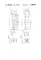
- FIG. 2 shows a portion of the lattice from which the signalling constellation used in the transmitter is chosen
- FIG. 3 is a trellis diagram depicting the trellis code used in the transmitter of FIG. 1;
- FIG. 4 is a block diagram of the trellis coder used in the transmitter of FIG. 1;
- FIGS. 5-12 are charts helpful in understanding the illustrative embodiment.
- FIG. 13 is a block diagram of a receiver adapted to recover the data encoded and transmitted by the transmitter of FIG. 1 after having passed through a (1-D) partial response channel.
- S/P serial-to-parallel
- the task of the transmitter of FIG. 1 is to convey to a receiver (shown in FIG. 13) signals representing respective signal points of a constellation wherein the points of the constellation are points from a predetermined p-dimensional lattice.
- p p
- the bits on leads 13a-b referred to herein as the "trellis-coded bits" are applied to a rate 2/3 trellis coder of conventional design.
- the output of coder 15 on leads 16 is a three-bit word identifying one of eight predetermined subsets of points of the aforementioned constellation.
- the subsets more particularly, are illustratively cosets of a predetermined sublattice of the lattice.
- seed generator ROM 21 receives as inputs the two bits on leads 12a-b, referred to herein as the "non-trellis-coded bits".
- seed generator ROM 21 receives as a further input a signal from leads 18 as will be described.
- the job of seed generator ROM 21 is to generate a two-dimensional signal point (x i ,y i ) whose two components x i and y i are provided on leads 22 and 23, respectively.
- the subscript "i" advances at the signalling rate, i.e., the rate that S/P converter 11 puts out words on its output leads.
- the components x i and y i are applied to parallel-to-serial (P/S) converter 31.
- P/S parallel-to-serial
- the latter provides on its output leads 32 a multi-bit word representing x i , followed by a multi-bit word representing y i .
- These are applied to a conventional baseband pulse generator 40 which, for each word applied thereto, generates a baseband pulse whose amplitude is given by the input word value.
- the output of generator 40 is applied to the transmission channel.
- the channel is assumed to be a so-called partial response channel.
- Such channels like virtually all real-world channels, still add a measure of noise to the transmitted signal.
- the partial response channel assumed for this embodiment operates on the transmitted signal in such a way that the value of each signal pulse received at the output of the channel is equal to the difference between the value of a particular transmitted pulse and the value of the pulse transmitted immediately before it.
- Such a channel is referred to as a (1-D) channel.
- the most likely sequence of transmitted signal points can be ascertained at the receiver using, for example, straightforward Viterbi decoding to identify the correct sequence of cosets.
- straightforward Viterbi decoding to identify the correct sequence of cosets.
- the most likely sequence of signal points cannot be deduced without substantially increasing the complexity of the Viterbi decoder.
- the present invention provides a mechanism which allows trellis-coded signals to be transmitted over a partial response channel and accurately decoded at the receiver using a decoding arrangement which is no more complex than that which is currently used to decode trellis coded signals transmitted over non-partial-response channels.
- the coding gain advantages afforded by trellis coding generally are thus extended in a practical way to the realm of the transmission of data over partial response channels.
- a useful way to begin is to choose a lattice L from which the points of the signalling constellation are chosen.
- the lattice L the lattice of all two-dimensional points whose components are integers.
- Mathematically such a lattice is said to be the lattice spanned by the vectors (1,0) and (0,1).
- a so-called sublattice M is chosen.
- the sublattice M is a lattice comprised of a subset of points of the lattice L.
- the sublattice M consists of all points in the lattice L whose norm is divisible by 8, the norm of a point being the sum of the squares of the components.
- such a sublattice is said to be the lattice spanned by the vectors (2,2) and (2,2). It includes such points as (0,0), (2,2), (2,ovs/2/ ), (4,0), etc., where 2 is the notational equivalent of -2.
- the cosets of the sublattice are the unique sets of points in the lattice obtained by various translations of the sublattice.
- there are eight cosets of M in L which, for convenience, can each be labeled with a representative point from the coset.
- the labels are the representative points (0,0), (2,0), (1,1), (1,3), (0,3), (0,1), (3,0) and (1,0).
- FIG. 2 shows a portion of lattice L with the various points denominated with the label of the coset to which they belong.
- the underlying theory of trellis coding is that at any point in time, only the points in particular cosets, as defined by a so-called trellis diagram, are allowed to be transmitted.
- trellis coder 15 has eight "states", denoted 000, 100, 010, 110, 001, 101, 011, and 111.
- the state of a trellis coder is a function of at least one bit of at least one input word received prior to the current input word.
- the state of the coder is a function of (a) the two bits applied to the coder previous to the two current bits and (b) one of the bits applied to the coder previous to that.
- the two vertical lines of points in FIG. 3 represent the eight possible coder states at successive time intervals, and the lines, or edges, connecting various pairs of states indicate the possible state transitions. Thus, for example, it is possible for the coder to transition from state 010 to state 001 but not to state 100.
- Each of these connecting lines bears a label indicating which coset the next signal point to be generated is to come from.
- the current state of the coder is 001 and that when the next set of bits is output from S/P converter 11, the bit pair on leads 13a-b is "11". This means that the next signal point to be generated is to come from coset (0,1) since the line connecting state 001 in the left column to state 111 in the right column is labeled (0,1).
- a circuit embodiment of trellis coder 15 is shown in FIG. 4.
- the two current bits applied to the coder are applied thereto from leads 13a-b.
- the two bits previously applied to the coder are held in one-bit delay elements 151 and 152.
- the bit applied to the coder on lead 13b before that is held in one-bit delay element 153, which gets its input from the output of delay element 152.
- the values held in the three delay elements are applied to binary adders 155 and 156, along with the values of the two current bits on leads 13a-b, in the manner shown.
- Each binary adder outputs a "0" ("1") if an even (odd) number of its input bits has the value "1".
- the outputs of delay elements 152 along with the outputs of adders 155 and 156 constitute the output word of the coder, thereby identifying which of the eight cosets the next signal point to be generated belongs to.
- the trellis coder outputs 000, 001, 010, 011, 100, 101, 110 and 111 identify the cosets (0,0), (2,0), (1,1), (1,3), (1,0) (3,0), (0,3) and (0,1), respectively.
- those k bits are used in conjunction with a) the coset-identifying word on leads 16 and b) the value of the channel state, which for a (1-D) channel is given by y i-1 , i.e., the second component of the previous point applied to the channel, appearing on output leads 18 of 1-baud delay element 17, to identify what I refer to as a "seed".
- the seed is a p-dimensional point which, in general, is not in the selected coset. Indeed, the seed need not, in general, be in the lattice L (although it turns out that all the seeds are in lattice L in this embodiment). And it is the seed, rather than a point from the selected coset, that is applied to the channel via converter 31 and generator 40.
- the seed is chosen with a number of criteria in mind. First of all, it is necessary that once the seed has passed through the partial response channel, the resultant signal point presented to the receiver must be a point in the coset identified by the trellis coder, hereinafter referred to as the "target" coset. By ensuring this, it can be ensured that Viterbi decoding of no greater complexity than is needed to recover the trellis-coded bits in a non-partial-response transmission system can be used to reconstruct the sequential states of trellis coder 15 in the transmitter and thereby recover the trellis-coded bits on leads 13a-b.
- seed generator ROM 21 must be able to transmit a number of different seeds to represent each possible combination of the non-trellis-coded bits on leads 12a-b.
- seed generator ROM 21 must be able to transmit a number of different seeds to represent each possible combination of the non-trellis-coded bits on leads 12a-b.
- a seed when transmitted, is subject to being altered by the (1-D) channel in a way that, depends on the number of different possible channel states, i.e., the different possible values of y i-1 .
- an ensemble of seeds referred to herein as a "seed alphabet”
- each seed alphabet needs to contain four seeds since there are four different possible combinations of values of the non-trellis-coded bits on leads 12a-b. And, to repeat, each of those seeds must be such that, when it is altered by the (1-D) operation of the partial response channel, the resultant signal point applied to the receiver is a point in the target coset identified by trellis coder 15. It will thus be appreciated that the seed that is output by ROM 21 is identified by (a) the target coset, (b) the channel state, and (c) the values of the non-trellis-coded bits.
- Viterbi decoding of the cosets in the conventional way can certainly be used in the receiver to deduce the most likely sequence of the eight states of trellis coder 15 and, thus, to deduce the most likely sequence of bits on leads 13a-b.
- Such an approach will not, however, deduce the encoder channel states and thus will not be able to determine which seed alphabet the received signal point originated from.
- This is significant because, in general, at least some signal points can appear at the receiver as the result of the transmission of seeds from different ones of the seed alphabets associated with a particular target coset. Thus not knowing which seed alphabet the received signal point originated from means that, in general, it is not possible to recover the non-trellis-coded bits therefrom.
- One alternative would be to employ more complex Viterbi decoding to, in fact, derive the most likely sequence of the 8 ⁇ 4 32 trellis coder state/channel state combinations and thus determine which seed alphabet the transmitted seed originated from. Armed with the identity of the seed alphabet, it would be possible to work backwards using (a) the non-trellis-coded-bit-to-seed assignment scheme for that seed alphabet and (b) the received point itself to recover the non-trellis-coded bits.
- FIGS. 5-12 each of which includes an encoder decision rule table showing, for a respective target coset, (a) the four seed alphabets associated with the four channel states and (b) the non-trellis-coded-bits-to-seed assignment scheme.
- FIG. 5 shows the seed alphabets and assignment scheme for the target coset (0,0).
- the four channel states are labeled 0, 1, 1, and 2, corresponding to the four possible values that y i --which becomes y i-1 in the subsequent signalling interval--can take on in this embodiment.
- each channel state Listed in a column under each channel state are the seeds of the associated seed alphabet, such as the seeds (0,0), (2,0), (2,0), and (4,0) associated with channel state "0".
- the seed of the associated seed alphabet such as the seeds (0,0), (2,0), (2,0), and (4,0) associated with channel state "0".
- each of the signal points in the "received signal” column is, indeed, a member of the target coset (0,0), as can be verified from FIG. 2.
- all the seeds whose transmission results in the receipt of a particular one signal point have assigned to them a particular one combination of non-trellis-coded bit values.
- all of the seeds whose transmission results in the receipt of the signal point (2,2) have assigned to them the non-trellis-coded bit pair values 01.
- FIGS. 6-12 include similar encoder decision rule tables, each for a different target coset.
- a ⁇ in the "received signal point" column means that the received signal point following the ⁇ is either the one actually listed or the signal point derived by changing the signs of both components.
- two of the seeds associated with the non-trellis-coded bit pair 10 result in the received signal point (2,4) while the other two result in the received signal point (2,4).
- each of the four seeds associated with the bit pair 11 results in a different one of the received signal points (3,5), (3,5), (5,3) and (5,3).
- the encoder decision rule table in each of FIGS. 5-12 is graphically embodied in a channel state trellis diagram shown next to each table.
- the points in the left-hand column of points represent the four possible channel states, corresponding to the four possible values of y i-1 .
- the points in the right-hand column of points represent the four possible values of y i which, of course, will become y i-1 in the next signalling interval.
- the lines, or "edges", connecting the various pairs of states indicate the possible state transitions. Specifically, it is the case in every channel state trellis diagram that, from a given channel state, there is only one channel state that can be transitioned to.
- trellis coder 15 may specify any of the eight cosets as the target coset at any point in time.
- trellis coder 15 may specify any of the eight cosets as the target coset at any point in time.
- each coset can be characterized by the congruence, modulo 4, of the components of each member of the coset.
- x is congruent to y, modulo 4, if (x-y)/4 is an integer.
- x is congruent to y, modulo 4, if (x-y)/4 is an integer.
- 0, 4, 8, etc. are congruent to 0 modulo 4; 1, 5, 9, etc. are congruent to 1 modulo 4; 2, 6, 10, etc. are congruent to 2 modulo 4; and 3, 7, 11, etc.
- all the members of the coset (3,0) have a congruence, modulo 4 of either (3,0) or (1,2), meaning that the first and second components of each member of the coset are either congruent to 3 and 0, respectively--such as the point (1,0)--or are congruent to 1 and 2, respectively--such as the point (1,2).
- any such point will do because as long as y i is congruent to 3 modulo 4 and x i is odd, the received signal point is guaranteed to be in the target coset (3,0), which is all that we care about from the standpoint of constructing the channel state trellis diagram.
- the target coset (3,0)
- considerations of minimizing the signal power introduced into the channel makes it advantageous to choose a value having the lowest possible magnitude, which in this case is 1. Instead, the overall collection of seeds will typically be chosen so as to minimize the average transmitted power of the collection.
- the present y i is the future y i-1 . That is, the fact that y i has the value 1 means that, at some future time, the encoder will reside in the channel state 1. And, inevitably, trellis coder 15 will again specify (3,0) as the target coset. It is thus necessary to have a point labeled "1" in the y i-1 column of the FIG. 10 channel state trellis diagram.
- each existing edge of the diagram can be regarded as a family of edges each of whose initial states have a particular congruence and each of whose final states have a particular congruence, with each edge of the family bearing the same label.
- the present embodiment could be expanded to have eight channel states--the original four states 0, 1, 1, and 2, and four new states 4, 3, 3, and 2.
- the edge, for example, connecting channel states “0” and “1” in FIG. 10 can thus be expanded to four edges, namely edges connecting channel states “0” and “1", “0” and “3", “4" and “1", "4" and “3". All such edges will bear the label "1" for x i , indicating that all seeds defined by these edges--like the original one edge--have x i odd.
- the receiver of FIG. 13, in particular, is of conventional design.
- the stream of baseband pulses on the channel is applied to A/D converter 71 and thence through a conventional equalizer 72 which compensates for distortion in the channel and provides a signal on its output lead 73 representing the stream of received pulses.
- the pulses on lead 73 are converted into two multi-bit words by S/P coverter 74.
- S/P converter 74 provides on each of its two sets of multi-bit output leads 75a and 75b a multi-bit signal representing x i ' and y i ', respectively i.e., the value of the first and second components of the current received signal point.
- these component values are not whole integers, due to a possible myriad of channel effects and impairments that equalizer 72 was not able to compensate for.
- a typical received signal point might be, for example (2.1, -1.9).
- Viterbi decoder 76 It is the task of Viterbi decoder 76, which receives the signal point on leads 75a-b, to determine the most likely sequence of signal points.
- the Viterbi decoder is of conventional design and need not be discussed in detail. (For details on the operation of Viterbi decoders, see, for example, A.J. Viterbi and J.K. Omura, Principles of Digital Communication and Coding (New York: McGraw-Hill) 1979, hereby incorporated by reference.) Rather, it suffices to note that decoder 76 applies the so-called Viterbi algorithm to the trellis of FIG.
- Viterbi decoder 76 provides (a) the estimated sequence of signal points on multi-bit output leads 77, (b) a three-bit word identifying the coset from which the point on leads 77 comes, this on leads 79, and (c) the values of the two bits that appeared on leads 13a-b in the transmitter at the time that the corresponding seed was generated, this on leads 78.
- the two bits that appeared on leads 12a-b at that time are recovered from the signals on leads 77 and 79.
- those signals are applied to ROM 83.
- the latter includes eight internal lookup tables, one corresponding to each coset. Each table includes, in essence, the first and last columns of the encoder decision rule table (FIGS. 5-12) for the corresponding coset.
- ROM 83 is steered to the table for the coset in question. In this table it finds an entry for the signal point on lead 77 and locks up the corresponding k 32 2 non-trellis-coded bits (first column encoder decision rule table) and provides them on leads 84.
- the running sum of that which is delivered by the channel is simply given by (y i -y i-1 ), because the received signal point (x i ', y i ') has a +x i term and a-x i term. Moreover, since each y i is matched by a-y i in the next signalling interval, the running sum is guaranteed to be bounded. As is well known, this implies that the line signal at the channel output has a spectral null at dc.
- the concern would not be to minimize the average seed power, since the seeds are processed only within the encoder, but rather to minimize the average power of the signal points resulting from the (1-D) operation since that is what is put out on the channel.
- the ensemble of seeds would be chosen in such a way as to minimize the average power of the resulting signal points.
- the present invention can be implemented in a system using any of a myriad of trellis codes and constellation including, for example, constellation comprised of higher-dimensional points, such as four- or eight-dimensional points.
- the invention is not limited to dealing with (1-D) channels. Other channel characteristics can be dealt with by appropriate modeling of the channel state and generation of appropriate channel state trellis diagrams.
- system disclosed herein is embodied in the form of various discrete electronic building blocks and components
- the invention could equally as well be embodied in a system in which the functions of any one or more of those building blocks and components or, indeed, all of the function thereof, are realized by, for example, one or more appropriately programmed processors.
Abstract
Description
Claims (14)
Priority Applications (1)
| Application Number | Priority Date | Filing Date | Title |
|---|---|---|---|
| US07/017,894 US4788694A (en) | 1987-02-20 | 1987-02-20 | Trellis coding with substrates |
Applications Claiming Priority (1)
| Application Number | Priority Date | Filing Date | Title |
|---|---|---|---|
| US07/017,894 US4788694A (en) | 1987-02-20 | 1987-02-20 | Trellis coding with substrates |
Publications (1)
| Publication Number | Publication Date |
|---|---|
| US4788694A true US4788694A (en) | 1988-11-29 |
Family
ID=21785143
Family Applications (1)
| Application Number | Title | Priority Date | Filing Date |
|---|---|---|---|
| US07/017,894 Expired - Lifetime US4788694A (en) | 1987-02-20 | 1987-02-20 | Trellis coding with substrates |
Country Status (1)
| Country | Link |
|---|---|
| US (1) | US4788694A (en) |
Cited By (16)
| Publication number | Priority date | Publication date | Assignee | Title |
|---|---|---|---|---|
| EP0413505A1 (en) * | 1989-08-18 | 1991-02-20 | AT&T Corp. | Generalized viterbi decoding algorithms |
| US5040191A (en) * | 1987-02-24 | 1991-08-13 | Codex Corporation | Partial response channel signaling systems |
| US5159610A (en) * | 1989-05-12 | 1992-10-27 | Codex Corporation | Trellis precoding for modulation systems |
| US5208816A (en) * | 1989-08-18 | 1993-05-04 | At&T Bell Laboratories | Generalized viterbi decoding algorithms |
| US5287385A (en) * | 1990-12-20 | 1994-02-15 | Fujitsu Limited | Viterbi decoding system including variable-order equalizer |
| GB2274047A (en) * | 1992-12-31 | 1994-07-06 | Samsung Electronics Co Ltd | Convolutional encoder and trellis-coded modulator |
| US5351249A (en) * | 1991-07-19 | 1994-09-27 | Interdigital Technology Corporation | Trellis coded FM digital communications system and method |
| US5916315A (en) * | 1994-08-23 | 1999-06-29 | Ampex Systems Corporation | Viterbi detector for class II partial response equalized miller-squared signals |
| US6131180A (en) * | 1997-11-03 | 2000-10-10 | Ericsson, Inc. | Trellis coded modulation system |
| US6393598B1 (en) | 1995-04-20 | 2002-05-21 | Seagate Technology Llc | Branch metric compensation for digital sequence detection |
| US20040006735A1 (en) * | 2002-07-03 | 2004-01-08 | William Mar | Viterbi decoding device and method for processing multi-data input into multi-data output |
| US20040038654A1 (en) * | 2002-08-20 | 2004-02-26 | Globespanvirata Inc. | Method and apparatus for generating a 64 state 4-D trellis code in DMT |
| US20040153953A1 (en) * | 2003-02-03 | 2004-08-05 | Wilson Danny W. | Processor and method for convolutional decoding |
| US6864500B2 (en) | 2002-04-10 | 2005-03-08 | Micron Technology, Inc. | Programmable conductor memory cell structure |
| US20090319876A1 (en) * | 2008-06-24 | 2009-12-24 | Norikatsu Chiba | Maximum likelihood decoder and decoding method therefor |
| US7957370B2 (en) | 1993-02-01 | 2011-06-07 | Lake Cherokee Hard Drive Technologies, Llc | Synchronous read channel |
Citations (5)
| Publication number | Priority date | Publication date | Assignee | Title |
|---|---|---|---|---|
| US4489418A (en) * | 1983-04-18 | 1984-12-18 | At&T Bell Laboratories | Differential encoding technique |
| US4581601A (en) * | 1984-06-25 | 1986-04-08 | At&T Bell Laboratories | Multi-dimensional coding for error reduction |
| US4597090A (en) * | 1983-04-14 | 1986-06-24 | Codex Corporation | Block coded modulation system |
| US4601044A (en) * | 1983-11-04 | 1986-07-15 | Racal Data Communications Inc. | Carrier-phase adjustment using absolute phase detector |
| US4660214A (en) * | 1985-08-01 | 1987-04-21 | Infinet, Inc. | QANI Trellis-coded signal structure |
-
1987
- 1987-02-20 US US07/017,894 patent/US4788694A/en not_active Expired - Lifetime
Patent Citations (5)
| Publication number | Priority date | Publication date | Assignee | Title |
|---|---|---|---|---|
| US4597090A (en) * | 1983-04-14 | 1986-06-24 | Codex Corporation | Block coded modulation system |
| US4489418A (en) * | 1983-04-18 | 1984-12-18 | At&T Bell Laboratories | Differential encoding technique |
| US4601044A (en) * | 1983-11-04 | 1986-07-15 | Racal Data Communications Inc. | Carrier-phase adjustment using absolute phase detector |
| US4581601A (en) * | 1984-06-25 | 1986-04-08 | At&T Bell Laboratories | Multi-dimensional coding for error reduction |
| US4660214A (en) * | 1985-08-01 | 1987-04-21 | Infinet, Inc. | QANI Trellis-coded signal structure |
Cited By (26)
| Publication number | Priority date | Publication date | Assignee | Title |
|---|---|---|---|---|
| US5040191A (en) * | 1987-02-24 | 1991-08-13 | Codex Corporation | Partial response channel signaling systems |
| US5159610A (en) * | 1989-05-12 | 1992-10-27 | Codex Corporation | Trellis precoding for modulation systems |
| US5208816A (en) * | 1989-08-18 | 1993-05-04 | At&T Bell Laboratories | Generalized viterbi decoding algorithms |
| EP0413505A1 (en) * | 1989-08-18 | 1991-02-20 | AT&T Corp. | Generalized viterbi decoding algorithms |
| US5287385A (en) * | 1990-12-20 | 1994-02-15 | Fujitsu Limited | Viterbi decoding system including variable-order equalizer |
| US5661734A (en) * | 1991-07-19 | 1997-08-26 | Interdigital Technology Corporation | Trellis coded FM digital communications system and method |
| US5862155A (en) * | 1991-07-19 | 1999-01-19 | Interdigital Technology Corporation | Trellis coded FM digital communications system and method |
| US5351249A (en) * | 1991-07-19 | 1994-09-27 | Interdigital Technology Corporation | Trellis coded FM digital communications system and method |
| US5461632A (en) * | 1991-07-19 | 1995-10-24 | Interdigital Technology Corporation | Trellis coded FM digital communications system and method |
| DE4344811B4 (en) * | 1992-12-31 | 2004-08-12 | Samsung Electronics Co., Ltd., Suwon | Convolutional encoder and grid-coded modulation device with a convolutional encoder |
| GB2274047A (en) * | 1992-12-31 | 1994-07-06 | Samsung Electronics Co Ltd | Convolutional encoder and trellis-coded modulator |
| FR2700226A1 (en) * | 1992-12-31 | 1994-07-08 | Samsung Electronics Co Ltd | Modulation system by trellis coding. |
| GB2274047B (en) * | 1992-12-31 | 1996-09-25 | Samsung Electronics Co Ltd | Trellis-coded modulation system and convolutional encoder |
| US7957370B2 (en) | 1993-02-01 | 2011-06-07 | Lake Cherokee Hard Drive Technologies, Llc | Synchronous read channel |
| US5916315A (en) * | 1994-08-23 | 1999-06-29 | Ampex Systems Corporation | Viterbi detector for class II partial response equalized miller-squared signals |
| US6393598B1 (en) | 1995-04-20 | 2002-05-21 | Seagate Technology Llc | Branch metric compensation for digital sequence detection |
| US6131180A (en) * | 1997-11-03 | 2000-10-10 | Ericsson, Inc. | Trellis coded modulation system |
| US6864500B2 (en) | 2002-04-10 | 2005-03-08 | Micron Technology, Inc. | Programmable conductor memory cell structure |
| US20040006735A1 (en) * | 2002-07-03 | 2004-01-08 | William Mar | Viterbi decoding device and method for processing multi-data input into multi-data output |
| US7185269B2 (en) * | 2002-07-03 | 2007-02-27 | Via Optical Solution, Inc. | Viterbi decoding device and method for processing multi-data input into multi-data output |
| US20040038654A1 (en) * | 2002-08-20 | 2004-02-26 | Globespanvirata Inc. | Method and apparatus for generating a 64 state 4-D trellis code in DMT |
| US7346118B2 (en) | 2002-08-20 | 2008-03-18 | Brooktree Broadband Holding, Inc. | Method and apparatus for generating a 64 state 4-D Trellis code in DMT |
| US20040153953A1 (en) * | 2003-02-03 | 2004-08-05 | Wilson Danny W. | Processor and method for convolutional decoding |
| US7171609B2 (en) * | 2003-02-03 | 2007-01-30 | Verisilicon Holdings Company Ltd. | Processor and method for convolutional decoding |
| US20090319876A1 (en) * | 2008-06-24 | 2009-12-24 | Norikatsu Chiba | Maximum likelihood decoder and decoding method therefor |
| US7937650B2 (en) * | 2008-06-24 | 2011-05-03 | Kabushiki Kaisha Toshiba | Maximum likelihood decoder and decoding method therefor |
Similar Documents
| Publication | Publication Date | Title |
|---|---|---|
| US5548615A (en) | Methods and apparatus for rotationally invariant multilevel coding | |
| US4788694A (en) | Trellis coding with substrates | |
| US5329551A (en) | Overlapped multilevel codes | |
| US4823346A (en) | Maximum likelihood decoder | |
| EP0566330B1 (en) | Multilevel coding using trellis-coded modulation and reed-solomon codes | |
| CA1212419A (en) | Differentially nonlinear convolutional channel coding with expanded set of signalling alphabets | |
| Lin et al. | Error Control | |
| US4713817A (en) | Multidimensional, convolutionally coded communication systems | |
| US4939555A (en) | Trellis coding arrangement | |
| US5115453A (en) | Technique for designing a multidimensional signaling scheme | |
| US5243627A (en) | Signal point interleaving technique | |
| US5418798A (en) | Multidimensional trellis-coded communication system | |
| US5488633A (en) | Intersymbol interference channel coding scheme | |
| US4489418A (en) | Differential encoding technique | |
| EP0206770A2 (en) | Coded modulation system with a simplified decoder capable of reducing the effects of channel distortion | |
| US4457004A (en) | Multidimensional channel coding | |
| CA2124376A1 (en) | Method and apparatus for encoding data for transfer over a communication channel | |
| JPH08265386A (en) | Rotary constant lattice coding device accompanied by transparent binary folding code and its method | |
| EP0476125A1 (en) | Treillis precoding for fractional bits/baud | |
| US5265127A (en) | Non-linear encoder and decoder for information transmission through non-linear channels | |
| US5841818A (en) | Decoding method for trellis codes employing a convolutional processor | |
| US5703911A (en) | Decoding method for trellis codes with large free distances | |
| US4831635A (en) | Trellis codes with spectral nulls | |
| GB2207583A (en) | Method and apparatus for transmitting data over a channel | |
| US5982818A (en) | Method for implementing trellis codes for ISI channels |
Legal Events
| Date | Code | Title | Description |
|---|---|---|---|
| AS | Assignment |
Owner name: AMERICAN TELEPHONE AND TELEPHONE AND TELEGRAPH COM Free format text: ASSIGNMENT OF ASSIGNORS INTEREST.;ASSIGNOR:CALDERBANK, ARTHUR R.;REEL/FRAME:004712/0850 Effective date: 19870220 Owner name: BELL TELEPHONE LABORATORIES, INCORPORATED, 600 MOU Free format text: ASSIGNMENT OF ASSIGNORS INTEREST.;ASSIGNOR:CALDERBANK, ARTHUR R.;REEL/FRAME:004712/0850 Effective date: 19870220 |
|
| STCF | Information on status: patent grant |
Free format text: PATENTED CASE |
|
| CC | Certificate of correction | ||
| FPAY | Fee payment |
Year of fee payment: 4 |
|
| FEPP | Fee payment procedure |
Free format text: PAYOR NUMBER ASSIGNED (ORIGINAL EVENT CODE: ASPN); ENTITY STATUS OF PATENT OWNER: LARGE ENTITY |
|
| FPAY | Fee payment |
Year of fee payment: 8 |
|
| FEPP | Fee payment procedure |
Free format text: PAYER NUMBER DE-ASSIGNED (ORIGINAL EVENT CODE: RMPN); ENTITY STATUS OF PATENT OWNER: LARGE ENTITY Free format text: PAYOR NUMBER ASSIGNED (ORIGINAL EVENT CODE: ASPN); ENTITY STATUS OF PATENT OWNER: LARGE ENTITY |
|
| FPAY | Fee payment |
Year of fee payment: 12 |