US4809041A - Image forming apparatus with storage of processing modes - Google Patents
Image forming apparatus with storage of processing modes Download PDFInfo
- Publication number
- US4809041A US4809041A US07/011,754 US1175487A US4809041A US 4809041 A US4809041 A US 4809041A US 1175487 A US1175487 A US 1175487A US 4809041 A US4809041 A US 4809041A
- Authority
- US
- United States
- Prior art keywords
- mode
- image processing
- processing
- memory
- processing mode
- Prior art date
- Legal status (The legal status is an assumption and is not a legal conclusion. Google has not performed a legal analysis and makes no representation as to the accuracy of the status listed.)
- Expired - Lifetime
Links
Images


Classifications
-
- G—PHYSICS
- G03—PHOTOGRAPHY; CINEMATOGRAPHY; ANALOGOUS TECHNIQUES USING WAVES OTHER THAN OPTICAL WAVES; ELECTROGRAPHY; HOLOGRAPHY
- G03G—ELECTROGRAPHY; ELECTROPHOTOGRAPHY; MAGNETOGRAPHY
- G03G15/00—Apparatus for electrographic processes using a charge pattern
- G03G15/50—Machine control of apparatus for electrographic processes using a charge pattern, e.g. regulating differents parts of the machine, multimode copiers, microprocessor control
Definitions
- the present invention relates to an image forming apparatus.
- an image is read at an image reading section (reader) in an operating mode set through an operating section, processed for image editing, image storage, image transmission and the like, and outputted as a reproduced image from an image output section (printer).
- an operator handles various operating mode setting switches disposed on the operating section to set a desired operating mode while viewing displays. For instance, to obtain five copies of an image on A4 size recording paper at an image forming magnification of 124% and at a standard image density, the operator selects proper operating mode setting switches on the operating section to correctly set a desired operating mode while confirming it on the displays.
- the number of setting switches on the operating section and the number of displays increase as the image forming functions increase in number.
- an inexperienced operator often handles the switches erroneously.
- the same operating mode must be set a second time due to interruption while forming an image.
- the operator must go to the trouble of setting an operating mode each time an image is to be formed, thus extraordinarily degrading the image forming efficiency.
- An object of the present invention is to eliminate the above-described disadvantages.
- Another object of the present invention is to provide an image forming apparatus capable of setting and storing an operating mode with simple operations and preventing the same operating mode from being stored.
- a further object of the present invention is to provide an image forming apparatus capable of setting and storing an operating mode with simple operations.
- a still further object of the present invention is to provide an image forming apparatus capable of automatically storing an operating mode with simple operations.
- Another object of the present invention is to provide an image forming apparatus capable of storing an operating mode and reading it at any time with simple operations.
- FIG. 1 is a block diagram for explaining the construction of an embodiment of the image forming appartus according to the present invention
- FIG. 2 is a perspective view of an exemplified embodiment of the image forming apparatus according to the present invention.
- FIG. 3 is an enlarged, plan view showing the operating section shown in FIG. 2;
- FIG. 4 is a flow chart showing an example of the operation of storing and reading an operating mode according to the present invention
- FIG. 5 is a detailed diagram showing the operating mode memory means
- FIG. 6 is a flow chart showing an example of the operation of storing and reading an operating mode
- FIG. 7 is an enlarged, plan view of the operating section shown in FIG. 2;
- FIG. 8 is a flow chart showing an example of the operation of storing an operating mode according to the present invention.
- FIG. 9 is a flow chart showing an example of the operation of setting an operating mode according to the present invention.
- FIG. 1 is a block diagram showing the construction of an embodiment of the image forming apparatus according to the present invention.
- a controller 1 is constructed, for example, of a microcomputer including a ROM storing programs for image processing, and a RAM. The controller 1 also functions as the operating mode setting means and write control means referred to below.
- An image input means 2 is constructed, for example, of an optical scanner for reading an image with an image pickup element such as a CCD and outputting electric signals.
- An image output means 3 is constructed, for example, of a laser beam printer for forming an image based on the electric signals.
- An operating section 4 is constructed of switches 4a for setting a function necessary for image processing, and 4b.
- An operating mode memory means 5 is constructed, for example, of a battery back-up RAM, and sequentially stores, as an operating mode, an image processing function necessary for forming an image and set by the operating section 4.
- a number of switches 4a for setting an image processing function necessary for forming an image, and displays 4b, are disposed on the operating section 4.
- the controller 1 After the power is turned on and the controller 1 initializes the necessary circuits, if the operating section 4 instructs the machine to store a currently set image processing function as an operating mode, the controller 1 causes the currently set operating mode to be written in the operating mode memory means 5 and makes such effect to be displayed on a display 4b of the operating section 4. By repeating such operations, a plurality of operating modes representative of necessary image processing functions can be sequentially written in the operating mode memory means 5. If the same operating mode as that already stored in the operating mode memory means 5 has been set, the controller 1 inhibits it from being written in the operating mode memory means 5.
- a read command is inputted to the controller 1 by actuation of the switch 4a of the operating section 4. Then, the controller 1 accesses the operating mode memory means 5 to cyclically read operating modes starting from the newest one to find the desired operating mode and set it. When the operating section 4 raises an image forming command, the controller controls the image output means in accordance with the set operating mode. The read-out image information is sent to the image output means 3 to reproduce the image.
- FIG. 2 is a perspective view of an embodiment of the image forming apparatus according to the present invention.
- An image input section 11 optically reads the image of an original 11c set on an original support 11a with an original press plate 11b pressed thereupon.
- An operating section 11d can set plural image processing functions necessary for forming an image.
- An image output section 12 forms an image on a recording paper supplied from a paper feed cassette 12a or 12b.
- FIG. 3 is an enlarged, plan view of the operating section 11d shown in FIG. 2.
- a zoom key 23 sets a magnification ratio of an output image to the original 11c.
- a magnification ratio display 24 uses a 7 segment display for displaying a magnification ratio set by depressing the zoom key 23.
- An automatically variable magnification selection key 25 automatically sets a magnification ratio in accordance with the size of a recording paper of the paper feed cassette 12a or 12b.
- a paper selection key 26 selects either the paper feed cassette 12a or 12b which is loaded in the image output section 12.
- a photograph mode selection key 27 when it is depressed, effects a half-tone process such as a dither process for a photograph image read by the image input section 11.
- a density selection key 28 sets a desired image density of the read-out image.
- a density display 29 illuminates its light emitting diode when the density selection key 28 is depressed.
- a numeral display 30 displays numerals inputted using an enter key 31 and ten keys 32.
- a clear key 33 clears inputted numerals.
- a copy key 34 is used to start forming an image. The copy key 34 functions similarly to a store key described later.
- a stop key 35 is depressed to interrupt a copy operation.
- a reset key 36 when it is depressed, causes a standard mode to be restored instead of a special operating mode set by means of the described controls.
- a store key 37 is used to sequentially write a currently set operating mode in the operating mode memory means 5 each time it is depressed.
- a recall key 38 is used to cyclically read operating modes stored in the operating mode memory means 5, starting from the last stored operating mode, each time it is depressed.
- Each preset key 39 corresponding to one operating mode is used for reading an operating mode stored in a memory area corresponding to the depressed preset key.
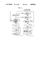
- FIG. 4 is a flow chart for explaining an operation example of storing and reading an operating mode according to the present invention.
- Reference numerals (1) to (12) represent process steps.
- a character N in the Figure represents the maximum number of operating modes storable in the operating mode memory means 5, which number can be determined as desired based on the hardware. Therefore, if N ⁇ 2, a one-to-one correspondence is not retained between the recall key and the memory area.
- i represents the count of an unrepresented counter, the count value being O to N-i and being used as address information on memory areas M O to M N-1 of the operating mode memory means 5 storing operating modes.
- One memory area M can store one operating mode having plural image forming functions (density setting, paper selection, inputted numerals and so on) necessary for forming an image.
- the flow starts when the power is turned on. First, depression of the copy key 34 is checked for at step (1). If YES, a copy operation is carried out, and it is checked at step (2) if the current copy mode coincides with one of the stored operating modes in the operating mode memory means 5, by reading the contents of the memory areas M O to M N-1 and comparing the readout content with the current copy mode. If YES, the flow returns to step (1). If NO, the count i is incremented by 1 at step (3) to check at step (4) if the count i exceeded the maximum number N. If NO, the flow jumps to step (6). If YES, the count i is cleared to "0" and thereafter, the currently set operating mode is stored at step (6) in the operating mode memory means 5 at the memory address Mi indicated by the count i to return to step (1).
- step (1) depression of the store key 37 is checked for at step (7). If YES at step (7), the flow goes to step (2). If NO, depression of the recall key 38 is checked for at step (8) to effect reading the operating modes stored in the operating mode memory means 5. If NO, the flow returns to step (1). If YES, it is checked at step (9) if the count i is "0" or larger. If YES, the flow jumps to step (11) and following steps. If NO, the maximum number N is inputted as the count i at step (10) and thereafter, the operating mode stored in the operating mode memory means 5 at the memory area Mi indicated by the count i is read at step (11), and the count i is decremented by 1 to return to step (1).
- the operating mode does not change. Further, a standard operating mode may be stored previously. The read-out operating mode may be changed upon actuation of each key on the operating section.
- FIG. 5 is a detailed diagram showing the operating mode memory means.
- a counter 6 is decremented by 1 upon depression of the recall key 38. The counter 6 indicates from which memory area Mj of the operating mode memory means 5 the data is to be read.
- a counter 7 is incremented by 1 upon depression of the copy key 34 or the store key 37. The counter 7 indicates in which memory area Mj of the operating mode memory means 5 the data is to be written.
- FIG. 6 An operation example of storing and reading an operating mode according to this embodiment is shown in the flow chart of FIG. 6. This flow chart is idential to that of FIG. 4 except that the count i at steps 9, 10 and 12 is changed to j.
- FIG. 7 is an enlarged, plan view of the operating section 11d shown in FIG. 2, wherein elements identical to those in FIG. 3 are designated using the same reference numerals.
- Preset keys 39a selectively turn on, when they are depressed, display elements 39b (12 elements).
- the preset key 39a enables one to store and read an operating mode. While a mode for storing an operating mode is set by keys 22 and when the preset key 39a is depressed, a currently setting operating mode is stored in the memory area corresponding to the depressed preset key. In a mode other than the above, an operating mode stored in the memory area corresponding to the depressed preset key 39 is read and set.
- a program key 40a corresponds to the store key 37 of FIG. 3. Upon depression of the program key 40a, a display 40b is turned on and the currently set operating mode is stored in the memory area of the operating mode memory means 5.
- a read key 40 corresponds to the recall key 38 of FIG. 3. Each time the read key 40 is depressed, a command issues to cause the operating modes stored in the operating mode memory means 5 to be sequentially read.
- FIG. 8 is a flow chart for explaining the operation of storing an operating mode according to this embodiment.
- References (1) to (15) represent flow steps.
- j in the Figure represents the key number of each preset key 39a, the number being 1 to 12.
- the number of image processing functions necessary for forming an image and stored in the operating mode memory means 5, is counted by an unrepresented counter whose count i is 1 to L (where L represents the upper limit of the number of operating modes, to be set properly depending on the memory capacity).
- the count i of the counter is initialized to "0" at step (1). Then, depression of the program key 40a is checked for at step (2). If NO, the flow jumps to step (13) and following steps. If YES, the display 40b is turned on to inform the operator of the program key depression at step (3). Next, the count i is decremented by 1 at step (4). Then, the controller 1 causes the currently set operation mode to be written in the operating mode memory means 5 at the memory space Mi at step (5). Next, it is checked if the count i is larger than L at step (6). If YES, an alarm is raised, for example, by temporarily flashing the display 40b or by producing an alarm voice at step (7) and thereafter, the display 40b is turned off at step (8).
- the number n of image processing functions is inputted as the count i at step (9). Succeedingly, depression of the stop key 35 is checked for at step (10). If YES, the flow returns to step (1). If NO, a depression of preset key 39a (j) is checked for at step (11). If NO, the flow returns to step (10). If YES, the number n of image processing functions is stored in the operating mode memory means 5 at the memory area Nj, and the content of the memory space Mi is written in the memory area Fij at step (12) to return to step (1). Thus, when the program key is depressed three times before the stop key is depressed, the contents of M 1 to M 3 are stored in F 1j to F 3j .
- step (6) depression of the stop key 35 is checked for at step (13). If NO, the flow returns to step (2). If YES, the display 40b is turned on at step (14). Next, it is checked at step (15) if the count i is "0" or not. If YES, the flow returns to step (2). If NO, the flow goes to step (9).
- FIG. 9 is a flow chart for explaining an operation example of setting an operating mode according to this embodiment.
- References (1) to (7) represent flow steps. It is assumed that the operating modes corresponding to the preset keys 39a (12 keys) have already been stored in the operating mode memory means 5.
- depression of the preset key 39a is awaited at step (1).
- the preset key 39a is depressed, it is checked at step (2) if the number n of image processing functions stored in the memory area Nj is "0" or not. If YES, the count i of the counter is set at "1" at step (3). Succeedingly, the ith operating mode stored in the operating mode memory means 5 is read at step (4) to change the operating mode before the depression of the preset key 39a.
- depression of the read key 41 is checked for at step (5). If NO, the flow returns to step (1).
- step (6) If YES, the count i is incremented by 1 at step (6), and it is checked at step (7) if the count i is smaller than the number n of image processing functions stored in the memory area Nj. If YES, the flow returns to step (4), whereas if NO, the flow returns to step (3).
Abstract
Description
Claims (24)
Applications Claiming Priority (8)
| Application Number | Priority Date | Filing Date | Title |
|---|---|---|---|
| JP61-26943 | 1986-02-12 | ||
| JP61026942A JPS62186644A (en) | 1986-02-12 | 1986-02-12 | Picture input/output device |
| JP61-26942 | 1986-02-12 | ||
| JP61026945A JPS62186647A (en) | 1986-02-12 | 1986-02-12 | Picture input/output device |
| JP61-26944 | 1986-02-12 | ||
| JP61-26945 | 1986-02-12 | ||
| JP61026944A JPS62186646A (en) | 1986-02-12 | 1986-02-12 | Picture input/output device |
| JP61026943A JP2515290B2 (en) | 1986-02-12 | 1986-02-12 | Image processing mode storage device |
Publications (1)
| Publication Number | Publication Date |
|---|---|
| US4809041A true US4809041A (en) | 1989-02-28 |
Family
ID=27458595
Family Applications (1)
| Application Number | Title | Priority Date | Filing Date |
|---|---|---|---|
| US07/011,754 Expired - Lifetime US4809041A (en) | 1986-02-12 | 1987-02-06 | Image forming apparatus with storage of processing modes |
Country Status (1)
| Country | Link |
|---|---|
| US (1) | US4809041A (en) |
Cited By (6)
| Publication number | Priority date | Publication date | Assignee | Title |
|---|---|---|---|---|
| US4924274A (en) * | 1987-09-25 | 1990-05-08 | Minolta Camera Kabushiki Kaisha | Copying machine |
| US4990954A (en) * | 1987-10-06 | 1991-02-05 | Minolta Camera Kabushiki Kaisha | Image forming apparatus having detachable data storage unit |
| EP0845714A1 (en) * | 1996-11-29 | 1998-06-03 | Kabushiki Kaisha Toshiba | Image forming apparatus |
| US6028968A (en) * | 1990-01-25 | 2000-02-22 | Canon Kabushiki Kaisha | Image processing apparatus |
| US6208434B1 (en) * | 1997-02-27 | 2001-03-27 | Brother Kogyo Kabushiki Kaisha | Copying apparatus in a facsimile machine |
| US20080002240A1 (en) * | 2006-06-21 | 2008-01-03 | Seiko Epson Corporation | Image reading apparatus and image reading system |
Citations (1)
| Publication number | Priority date | Publication date | Assignee | Title |
|---|---|---|---|---|
| US4494861A (en) * | 1976-05-21 | 1985-01-22 | Canon Kabushiki Kaisha | Copying apparatus |
-
1987
- 1987-02-06 US US07/011,754 patent/US4809041A/en not_active Expired - Lifetime
Patent Citations (1)
| Publication number | Priority date | Publication date | Assignee | Title |
|---|---|---|---|---|
| US4494861A (en) * | 1976-05-21 | 1985-01-22 | Canon Kabushiki Kaisha | Copying apparatus |
Cited By (10)
| Publication number | Priority date | Publication date | Assignee | Title |
|---|---|---|---|---|
| US4924274A (en) * | 1987-09-25 | 1990-05-08 | Minolta Camera Kabushiki Kaisha | Copying machine |
| US4990954A (en) * | 1987-10-06 | 1991-02-05 | Minolta Camera Kabushiki Kaisha | Image forming apparatus having detachable data storage unit |
| US6028968A (en) * | 1990-01-25 | 2000-02-22 | Canon Kabushiki Kaisha | Image processing apparatus |
| US6525834B2 (en) | 1990-01-25 | 2003-02-25 | Canon Kabushiki Kaisha | Image processing apparatus |
| EP0845714A1 (en) * | 1996-11-29 | 1998-06-03 | Kabushiki Kaisha Toshiba | Image forming apparatus |
| US6058249A (en) * | 1996-11-29 | 2000-05-02 | Kabushiki Kaisha Toshiba | Image forming apparatus |
| US6208434B1 (en) * | 1997-02-27 | 2001-03-27 | Brother Kogyo Kabushiki Kaisha | Copying apparatus in a facsimile machine |
| US20080002240A1 (en) * | 2006-06-21 | 2008-01-03 | Seiko Epson Corporation | Image reading apparatus and image reading system |
| US7535603B2 (en) * | 2006-06-21 | 2009-05-19 | Seiko Epson Corporation | Image reading apparatus and image reading system |
| CN101094295B (en) * | 2006-06-21 | 2010-06-23 | 精工爱普生株式会社 | Image reading apparatus and image reading system |
Similar Documents
| Publication | Publication Date | Title |
|---|---|---|
| US7403223B2 (en) | Method and apparatus for producing a file name in an image manipulating system having a memory device in which a file name and a second train of characters is provided wherein a file number is automatically generated by incrementing a file number previously assigned and stored in memory | |
| US5844693A (en) | Information processing apparatus and method for displaying information processing parameters and guidance information | |
| US5150462A (en) | Image data display system | |
| US6549236B2 (en) | Image reproduction apparatus with multiple-screen display mode | |
| JPH04306061A (en) | Picture processor | |
| US5991466A (en) | Image retrieving apparatus | |
| US4809041A (en) | Image forming apparatus with storage of processing modes | |
| US5572499A (en) | Image processing apparatus for storing image data in storage medium and/or for reproducing image stored in storage medium | |
| US5343560A (en) | Image data display system | |
| JPS6197784A (en) | Picture information retrieving device | |
| JP2556308B2 (en) | Image storage device | |
| US6760011B2 (en) | Keyboard apparatus | |
| EP0507527B1 (en) | Image storage control apparatus | |
| JP2515290B2 (en) | Image processing mode storage device | |
| JPH06178041A (en) | Image data output controller | |
| JPH0738733A (en) | Image forming device | |
| JPH11232007A (en) | Device and method for processing image and storage medium | |
| JP3230852B2 (en) | Image forming device | |
| JPS62186644A (en) | Picture input/output device | |
| JPS62186647A (en) | Picture input/output device | |
| JP2766484B2 (en) | Image forming device | |
| JP3071124B2 (en) | Printer that stores multiple forms | |
| JP3017833B2 (en) | Image forming device | |
| JPS62186646A (en) | Picture input/output device | |
| JPH03101362A (en) | Facsimile equipment |
Legal Events
| Date | Code | Title | Description |
|---|---|---|---|
| AS | Assignment |
Owner name: CANON KABUSHIKI KAISHA, 30-2, 3-CHOME, SHIMOMARUKO Free format text: ASSIGNMENT OF ASSIGNORS INTEREST.;ASSIGNOR:FUNADA, MASAHIRO;REEL/FRAME:004669/0396 Effective date: 19870204 Owner name: CANON KABUSHIKI KAISHA, A CORP OF JAPAN,JAPAN Free format text: ASSIGNMENT OF ASSIGNORS INTEREST;ASSIGNOR:FUNADA, MASAHIRO;REEL/FRAME:004669/0396 Effective date: 19870204 |
|
| STCF | Information on status: patent grant |
Free format text: PATENTED CASE |
|
| CC | Certificate of correction | ||
| FPAY | Fee payment |
Year of fee payment: 4 |
|
| FPAY | Fee payment |
Year of fee payment: 8 |
|
| FEPP | Fee payment procedure |
Free format text: PAYOR NUMBER ASSIGNED (ORIGINAL EVENT CODE: ASPN); ENTITY STATUS OF PATENT OWNER: LARGE ENTITY |
|
| FEPP | Fee payment procedure |
Free format text: PAYER NUMBER DE-ASSIGNED (ORIGINAL EVENT CODE: RMPN); ENTITY STATUS OF PATENT OWNER: LARGE ENTITY |
|
| FPAY | Fee payment |
Year of fee payment: 12 |