US4814680A - Servo loop control for a coriolis rate sensor dither drive - Google Patents
Servo loop control for a coriolis rate sensor dither drive Download PDFInfo
- Publication number
- US4814680A US4814680A US07/088,129 US8812987A US4814680A US 4814680 A US4814680 A US 4814680A US 8812987 A US8812987 A US 8812987A US 4814680 A US4814680 A US 4814680A
- Authority
- US
- United States
- Prior art keywords
- dither
- signal
- aiding
- rate sensor
- velocity
- Prior art date
- Legal status (The legal status is an assumption and is not a legal conclusion. Google has not performed a legal analysis and makes no representation as to the accuracy of the status listed.)
- Expired - Fee Related
Links
Images


Classifications
-
- G—PHYSICS
- G01—MEASURING; TESTING
- G01C—MEASURING DISTANCES, LEVELS OR BEARINGS; SURVEYING; NAVIGATION; GYROSCOPIC INSTRUMENTS; PHOTOGRAMMETRY OR VIDEOGRAMMETRY
- G01C19/00—Gyroscopes; Turn-sensitive devices using vibrating masses; Turn-sensitive devices without moving masses; Measuring angular rate using gyroscopic effects
- G01C19/56—Turn-sensitive devices using vibrating masses, e.g. vibratory angular rate sensors based on Coriolis forces
- G01C19/5776—Signal processing not specific to any of the devices covered by groups G01C19/5607 - G01C19/5719
Definitions
- the present invention generally pertains to a servo loop control and, specifically, to a Coriolis rate sensor drive controller.
- Angular rate of rotation about a given coordinate axis may be measured by moving (e.g., vibrating) an accelerometer along an axis normal to the accelerometer's sensitive axis and normal to the rate axis about which rotation is to be measured.
- moving e.g., vibrating
- an accelerometer along an axis normal to the accelerometer's sensitive axis and normal to the rate axis about which rotation is to be measured.
- the angular rotation vector of the body includes a component along the X axis, then periodic motion of the accelerometer along the Y axis will result in a periodic Coriolis acceleration acting in the Z direction that will be sensed by the accelerometer.
- the magnitude of the Coriolis acceleration is proportional to the rotation rate about the X axis.
- the output of the accelerometer includes a DC or slowly changing component that represents the linear acceleration of the body along the Z axis and a periodic component that represents the rotation of the body about the X axis.
- the accelerometer output can be processed, along with the outputs of accelerometers that have their sensitive axes in the X and Y directions and that are moved along the Z and X axes, respectively, to yield linear acceleration and angular rate about the X, Y and Z axes.
- the drive assembly described in the above-referenced patent application uses dual electromagnetic attractor coils that have several advantages over prior art solenoid and D-Arsonval torque coil dither drives. Regardless of the design of the dither drive, it is important that it be controlled to produce a stable dither motion. In addition, the control should provide a minimum settling time, i.e., the time required for the rate to achieve a stable dither amplitude should be insensitive to ambient temperature effects or voltage supply fluctuations, and should compensate for any phase shift between the driving force and the dither motion of the rate sensor that might create errors in the rotation rate signal due to harmonic distortion. Prior art dither drive controls have generally failed to address all these problems.
- the electromagnetic attraction coils used in the above-referenced drive assembly present other control problems.
- the driving force of the electromagnetic coils is directly proportional to the dither drive current squared and inversely proportional to the varying dimension of the magnetic pole gap squared. Both of these nonlinear second order effects cause the dither motion of the rotation rate sensor to deviate from a pure sine wave and introduce errors in the rotation rate determination.
- Prior art dither drive controls are incapable of properly compensating for the nonlinearities of the electromagnetic attractor coil dither drive.
- the present invention is directed to minimizing errors in the Coriolis rotation rate sensor output signal related to the dither drive, and compensating for problems that are common to all such drives, and for those specific to the electromagnetic attraction coil drive. Accordingly, it is an object of the present invention to provide a servo loop control for an attractor motor dither drive, which effects stable vibration of the Coriolis rate sensor and compensates for phase angle shift and nonlinearity in the driving force so that the dither motion of the rate sensor conforms to a sinusoidal function.
- a servo loop For use in controlling a Coriolis rate sensor dither drive, a servo loop is provided that includes feedback means for producing a position signal indicative of the displacement of the Coriolis rate sensor as it is driven to vibrate back and forth. Differentiating means are connected to the feedback means, in receipt of the position signal produced thereby, and are operative to differentiate that signal, providing a velocity signal that indicates the velocity of the rate sensor.
- the servo loop further includes driver means that produce a dither drive signal at a predetermined frequency, and both rate aiding and acceleration aiding signals, and summing means for summing these signals with the signals produced by the feedback means and the differentiating means.
- driver means that produce a dither drive signal at a predetermined frequency, and both rate aiding and acceleration aiding signals, and summing means for summing these signals with the signals produced by the feedback means and the differentiating means.
- the result is a servo loop output signal that controls the dither drive at a stable, fixed amplitude, as a function of the signals which are summed.
- the feedback means and the driver means each include a phaselocked loop referenced to a common, stable frequency reference.
- the feedback means, the differentiating means and the driver means are all provided power from a common power supply.
- the frequency of the output signal is thus extremely stable and is substantially independent of variations in the power supply voltage.
- the servo loop dither drive control is preferably intended for use with an attractor motor that includes an electromagnetic coil and core.
- the core is separated from the Coriolis rate sensor by a pole gap, which varies in dimension as the rate sensor dithers back and forth.
- the force of the dither drive is a function of the inverse of the pole gap dimension squared and of the current of the dither drive signal squared, both effects contributing to the nonlinearity of the driving force.
- Means are provided in the control for modifying the acceleration aiding signal to compensate for the nonlinearity of the attractor motor driving force.
- the modifying means also compensate for a phase shift that exists between the applied driving force and the Coriolis rate sensor dither motion. Modification of the acceleration aiding signal is accomplished by clipping the signal and passing it through a filter.
- the present invention also represents a method for carrying out functions analogous to those implemented by the above-described apparatus.
- FIG. 1 is a diagram conceptually illustrating a parallelogram assembly in which two accelerometers are mounted and are vibrated along an axis transverse to their preferred (i.e., sensitive) axes;
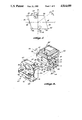
- FIG. 2 is an isometric view showing a parallelogram frame for a Coriolis rate sensor and a driving mechanism for vibrating the parallelogram frame, wherein the driving mechanism has been separated from its normal mounting position adjacent the frame;
- FIG. 3 is a side elevational view of the Coriolis rate sensor parallelogram frame and driving mechanism of FIG. 2;
- FIG. 4 is a top plan view of the Coriolis rate sensor and driving mechanism shown in FIGS. 2 and 3;
- FIG. 5 is an isometric cutaway view of the driving mechanism controlled by the present invention.
- FIG. 6 is a graph illustrating the normalized driving force of the electromagnetic attractor coil used in the driving mechanism as a function of the magnetic pole gap dimension
- FIG. 7 is a graph illustrating the relative shapes of the positive portion of a sin ⁇ function and a sin 2 ⁇ function, showing the nonlinearities in driving force resulting from the electromagnetic current squared;
- FIG. 8 is a graph of the normalized force multiplier that results from the nonlinear contributions of the electromagnetic current squared and the inverse of the pole gap dimension squared, as a function of phase angle;
- FIG. 9 is a graph illustrating the parallelogram frame response in terms of its dither amplitude (in dB) as a function of driving frequency and the phase shift of its motion (relative to the applied driving force) as a function of driving frequency;
- FIG. 10 illustrates the modified acceleration aiding waveform required to compensate for nonlinearities of the dither drive, and the approximation provided by the servo loop of the present invention
- FIG. 11 is a block diagram representing the servo loop control for the drive mechanism.
- FIG. 12 is a block diagram illustrating the phase-lock loop derivation of each of the signals used by the servo loop.
- FIG. 1 schematically illustrates a parallelogram arrangement for vibrating accelerometers 20 and 22 along the Y axis.
- the accelerometers are mounted with their sensitive axes substantially parallel to the Z axis and antiparallel to one another, the sensitive axis of accelerometer 20 being directed in a positive direction along the Z axis and the sensitive axis of accelerometer 22 being directed in a negative direction along the Z axis.
- Accelerometers 20 and 22 are secured to accelerometer support members 24 and 26, respectively, which in turn are connected to a pair of linkage members 28 and 30 by pivots 32 through 38.
- Linkage members 28 and 30 are mounted at central pivots 40 and 42, respectively.
- Support members 24 and 26 are both parallel to the Y axis.
- accelerometers 20 and 22 When linkage members 28 and 30 are vibrated about central pivots 40 and 42, respectively, accelerometers 20 and 22 will vibrate along the Y axis. Angular rotation ⁇ x about the X axis (the rotation-sensitive axis) produces a Coriolis force having an acceleration A z , which is detected by accelerometers 20 and 22.
- FIGS. 2 through 5 A preferred embodiment of an apparatus for implementing the vibrating parallelogram depicted graphically in FIG. 1 and a driving mechanism for driving the apparatus so that the accelerometers mounted thereon are vibrated back and forth, transverse to their sensitive axes, are shown in FIGS. 2 through 5.
- Reference numeral 50 generally denotes a parallelogram frame including two accelerometer support surfaces 24 and 26 on which are respectively mounted accelerometers 20 and 22, as indicated schematically in FIG. 1.
- Parallelogram 50 is preferably machined from a stainless steel having good flexural fatigue characteristics.
- Parallelogram frame 50 includes pivots at each of its four corners, defining a parallelogram comprising a flex member 52.
- Flex member 52 further includes linking members 28 and 30 that extend between accelerometer support members 24 and 26.
- the centers of linking members 28 and 30 are connected by flexures 40 and 42 to a crossbar mounting tab 54.
- Crossbar mounting tab 54 extends outwardly from the generally planar surface of flex member 52 and includes a mounting hole 56 through which a bolt (not shown) may be inserted to secure the parallelogram frame 50 to a supporting structure (not shown).
- the supporting structure would typically be a part of an object that is subject to angular motion and linear acceleration that the Coriolis rate sensor is intended to measure.
- parallelogram frame 50 is generally cubically shaped and includes a second flex member 52' which is substantially a mirror image of flex member 52, and which is aligned parallel with it.
- Flex member 52' includes substantially the same elements as flex member 52, e.g., flexures 32 through 42.
- a base plate (not shown) extends through the interior portion of parallelogram frame 50 between flex members 52 and 52' and is mounted on mounting tabs 100 which project inwardly from crossbar mounting tabs 54', secured by means of two bolts (not shown).
- a driving mechanism or motor 64 is provided to vibrate accelerometers 20 and 22 back and forth, in a direction transverse to their sensitive axes.
- Motor 64 includes a coil frame 66 in which are mounted two electromagnetic coils 70. Coils 70 are held in place by coil clamping bars 68, which are disposed on the top and bottom of coil frame 66, and are connected thereto with bolts 69.
- a mounting plate 72 extends outwardly from the center of coil frame 66 and includes two mounting holes 74 for attachment to the supporting structure of the body in which the Coriolis rate sensor is mounted.
- FIG. 5 The opposite surface of motor 64 is shown in FIG. 5, wherein it can be seen that mounting plate 72 is attached to a pivot plate 78 by means of a thin metal flexure 76.
- Pivot plate 78 is mounted within coil frame 66 so that both the pivot plate and the coil frame are free to pivot about the bending axis of flexure 76 relative to mounting plate 72.
- Electromagnetic coils 70 are each associated with a generally C-shaped core 80, the ends of which include two core faces 82 that face toward parallelogram frame 50 (see FIG. 4). Core faces 82 are slightly beveled so that their innermost edges extend outwardly slightly more than their outermost edges.
- pole pieces 84 are mounted in a notch formed within parallelogram frame 50, and are each disposed proximate to the core faces 82 of one of the electromagnetic coils 70.
- Each of pole pieces 84 has a pole face 86, which is also slightly beveled so that its innermost edge extends outwardly more than its outermost edge.
- motor 64 is directly connected to parallelogram frame 50 only by a thin sheet metal link 88 (shown with opposite ends broken away in FIGS. 2 and 5).
- One end of the link 88 is attached to parallelogram frame 50 with a bolt 90, while the other end is fixedly attached to coil frame 66, e.g., by spot welding.
- Electromagnetic coils 70 are alternately energized with a periodic drive current, creating an attractive force between first one and then the other of each pair of core 80 and pole piece 84.
- the alternating magnetic attraction between each pair of core 80 and pole piece 84 causes parallelogram frame 50 to vibrate, moving accelerometers 20 and 22 laterally back and forth as indicated schematically in FIG. 1.
- Link 88 forces coil frame 66 and parallelogram frame 50 to pivot back and forth exactly out of phase with each other, although normally the link is not required to transmit any force between the two frames unless the Coriolis rate sensor is subjected to an angular vibration about its rotation sensitive axis.
- Motor 64 provides an electromagnetic attractive driving force between cores 80 and pole pieces 84.
- This driving force is proportional to the square of the reciprocal of the variable distance 114 between core face 82 and pole face 86, i.e., 1/D 2 , where D equals the pole gap distance 114.
- FIG. 6 graphically illustrates the relationship between the driving force provided by the electromagnetic attraction between core 80 and pole piece 84 and the relative dimension of the pole gap distance 114, wherein these values are normalized so that at its center rest position, the gap dimension is equal to 1 and the driving force is equal to 1.
- the electromagnetic driving force increases by a factor of 4 as the pole gap dimension decreases to its minimum value, (normalized) 0.5.
- electromagnetic coil 70 when the other electromagnetic coil 70 is energized, it exerts an equivalent electromagnetic driving force on the opposite pole face 86.
- electromagnetic coils 70 In driving parallelogram frame 50 to vibrate back and forth, electromagnetic coils 70 are intended to provide only an attractive force, not a repulsive force.
- pole gap dimension 114 (normalized) is between 1.0 and 0.5.
- the drive current used to energize each electromagnetic coil 70 is nominally a sine wave, so that the coil is initially energized as the current passes through a phase angle of 0° (ignoring compensation for phase angle shift that may be applied as discussed hereinbelow).
- the pole gap dimension decreases to a minimum distance (normalized) of 0.5 as the current reaches a maximum of 90° into the sine wave.
- the attractive force at this pole gap dimension is four times the force at the 0° phase angle.
- the force provided by the electric current decreases, reaching its minimum (1.0) at a phase angle of 180° as the gap dimension 114 increases from 0.5 to a maximum of 1.0.
- the other electromagnetic coil 70 is energized, providing an equivalent increasing attractive force relative to the other pole face 86.
- Parallelogram frame 50 experiences the same increase in force as a function of the change in the gap dimension between core 82 and pole face 86 due to a decrease in the pole gap of the other electromagnetic coil 70.
- Parallelogram frame 50 is thus subjected to a substantially nonlinear attractor motor force caused by the change in gap dimension 114. Its motion does not conform to a pure sinusoidal function, unless the nonlinearity caused by the varying pole gap dimension 114 is corrected.
- the terms “nonlinearity” and “nonlinear” describe deviations from a pure sinusoidal waveform.
- a second source of nonlinear force applied to parallelogram frame 50 is a consequence of the force produced by electromagnetic coil70 being proportional to the drive current squared. Assuming that a sinusoidal drive current is applied to energize electromagnetic coils 70, the force resulting therefrom is proportional to a sine squared function rather than a sine function. The difference between these functions is illustrated in FIG. 7, wherein the positive portion of a sin ⁇ waveform and a sin 2 ⁇ waveform are plotted on the same axes, from 0 to 180° phase angle. Since the force applied to parallelogram frame 50 is proportional to the sin 2 ⁇ function, it is apparent that the dither motion of the prarallelogram frame produced by the force will deviate substantially from that of a pure sinusoidal waveform, unless compensation is provided.
- the two sources of nonlinearity in the force applied to vibrate parallelogram frame 50 by dither drive motor 64 combine with each other.
- the effect on the applied driving force resulting from both of these sources of nonlinearity is illustrated in FIG. 8, wherein a normalized force multiplier function is plotted as a function of the phase angle of the applied driving current.
- a normalized force multiplier function is plotted as a function of the phase angle of the applied driving current.
- the maximum effect caused by the reduction in pole gap dimension 114 is attained at a phase angle equal to 90°, corresponding to the peak of the instantaneous force multiplier curve. If the force applied to vibrate parallelogram frame 50 does not cause its motion to conform to a pure sinusoidal function, but instead deviates according to the force multiplier function illustrated in FIG.
- accelerometers 20 and 22 will produce a Coriolis rate signal which will contain errors of substantial magnitude. Such errors in part result from the occurrence of harmonics in the dither motion of the accelerometers, particularly the third harmonic, which can cause a substantial degradation in the accuracy of the rate signal.
- Parallelogram frame 50 has an inherent resonant frequency characteristic of its mass and the elasticity of flexures 32 through 42. In a preferred embodiment, the resonant frequency is tuned to approximately 102.5 Hz.
- the response in dB of parallelogram frame 50 to an applied driving force at frequencies between 10 Hz and 330 Hz is illustrated in FIG. 9. The resonance point at about 102-103 Hz is clearly evident from the very sharp peak in amplitude at that frequency, more than 40 dB above the 0 dB reference point. Since very little power is required to excite the parallelogram frame to vibrate at a frequency close to its resonance, motor 64 drives the rate sensor at a frequency of 100 Hz, only 2.5 Hz below the resonance point of the parallelogram frame 50.
- a dashed line in FIG. 9 shows the relative phase shift between the driving force applied to vibrate parallelogram frame 50 back and forth and the motor of the parallelogram frame in response to the driving force. It will be apparent that the phase shift has a very steep, almost asymtotic slope from 0° phase shift to -180° phase shift as parallelogram frame 50 passes through its resonance point.
- the phase shift at the selected 100 Hz driving frequency is approximately -15°, the minus sign indicating a lagging phase shift. Assuming that a pure sinusoidal force were applied to dither the accelerometers 20 and 22, parallelogram frame 50 would have a sinusoidal motion lagging 15° behind the applied force.
- the applied driving force is not a pure sinusoidal waveform, but instead deviates from a sinusoidal function according to the force multiplier curve of FIG. 8.
- the phase shift between the applied driving force complicates the correction of the nonlinear force applied to dither parallelogram frame 50.
- electromagnetic coils 70 By causing electromagnetic coils 70 to be energized with a signal that leads the desired sinusoidal motion of parallelogram frame 50 by a 15° phase angle, the resulting dither motion will be compensated for the phase shift.
- Compensation applied for the nonlinearities due to the pole gap (1/D 2 ) and the current (I 2 ) must also be phase shifted to compensate for the 15° lagging phase shift of the parallelogram frame.
- the resulting function is illustrated by the curved waveform in FIG. 10.
- This waveform compensates for both the (I 2 /D 2 ) nonlinearities and the 15° lagging phase shift motion of parallelogram frame 50 relative to the applied driving force.
- the electronic hardware required to produce the exact curved waveform shown in FIG. 10 would be complicated and expensive; however, the curved waveform can be approximated by the series of straight line segments overlaying the curved waveform in the manner illustrated. This approximation is generated as described below, with reference to an acceleration aiding input.
- a block diagram for the servo loop circuit controlling motor 64 is illustrated in FIG. 11.
- a linear variable differential transformer (LVDT) 106 disposed internally within parallelogram frame 50 (not shown in FIGS. 2-5), is operative to produce an electrical signal proportional to the displacement of accelerometers 20 and 22 relative to each other as they vibrate back and forth. Details of LVDT 106 are not shown, but it includes a carrier coil energized with a carrier signal and two pickup coils magnetically coupled to the carrier coil by a movable core. The variation in coupling between the coils caused by the motion of parallelogram frame 50 produces a modulated carrier signal.
- LVDT linear variable differential transformer
- the LVDT carrier coil is energized with a 12.8 kilohertz carrier signal, and its modulated output (modulated in proportion to the relative displacement of accelerometers 20 and 22), is amplified by an AC amplifier 108.
- the output signal from AC amplifier 108 is demodulated to produce a signal proportional to the displacement of parallelogram frame 50 as a result of the driving force produced by motor 64.
- the displacement of parallelogram frame 50 should conform to a sine wave function in phase with a sin ⁇ t driving signal applied to energize dither motor 64.
- the position signal output from demodulator 110 is summed with a sin ⁇ t drive signal, and with a null signal proportional to K/S (where K is a constant and S is the Laplacian operator) at summing junction 116 with the indicated signs applied to each of the signals.
- the null signal is a DC level used to compensate for misalignment of accelerometers 20 and 22 as explained in commonly assigned U.S. Pat. No. 4,665,748.
- the sum of these three signals is input to amplifier 118, wherein a gain factor K p is applied to scale for input to the next stage in the servo loop.
- the position signal output from demodulator 110 is also input to a differentiator 112, in which a Laplacian transform is applied to differentiate the signal to derive a velocity signal.
- Differentiator 112 includes a sample and hold circuit (not shown) used to determine the change in the position signal between two sample and hold values taken 80 microseconds apart in time, thereby determining the rate of change of position with time, or velocity.
- a velocity sensor could also be used to provide a velocity feedback signal, but deriving the velocity from the position is a simpler approach, avoiding the need for an additional sensor.
- the velocity signal output from differentiator 112 is input to summing junction 120 along with the output signal from amplifier 118, and a rate (or velocity) aiding input signal proportional to cos ⁇ t.
- the velocity signal should yield a cosine function in phase with the rate aiding input cos ⁇ t.
- the velocity feedback loop will produce a signal differing from that of the rate aiding input signal.
- the signals summed at junction 120 have the indicated signs applied and produce an output which is amplified by amplifier 122, with a gain factor K v , as required to properly scale the signal for the next stage.
- the acceleration aiding input Compensation for the nonlinearities due to the drive current (I 2 ), the pole gap dimension (1/D 2 ) and the phase shift of parallelogram frame 50 is provided by the acceleration aiding input.
- the acceleration aiding input could be provided by a pure -sin ⁇ t signal; however, because of these nonlinearities and phase shift, a more complex acceleration aiding input is required.
- the -sin ⁇ t function is phase shifted by ⁇ where ⁇ is equal to +15° leading.
- the resulting 31 sin ( ⁇ t+ ⁇ ) waveform is input to a limiter 126 which clips the input waveform to form the relatively truncated wave shape approximated by the straight lines in FIG. 10.
- the clipped sinusoidal output from limiter 126 is input to a high-pass filter 128, forming the sloping upper straight line portion of the approximation represented in FIG. 10.
- the output from high-pass filter 128, which now approximates the desired curved waveform shown in FIG. 10 is summed with the output from amplifier 122 at summing junction 124 and the resulting signal is input to voltage-to-current amplifier 130.
- the signal output from summing junction 124 represents the sum of the two feedback signals for position and velocity, the drive signal (sin ⁇ t), a velocity aiding signal (cos ⁇ t) and the acceleration aiding signal.
- Amplifier 130 converts the voltage of the signal output from summing junction 124 to a corresponding current that is used to energize the electromagnetic coils 70 of motor 64.
- each of the electromagnetic coils 70 is energized for one half cycle of the applied waveform. That waveform now includes the appropriate 15° leading phase shift to compensate for the lagging response of parallelogram frame 50.
- parallelogram frame 50 will dither in phase with the command sin ⁇ t drive signal input to summing junction 116 and will have a stable sinusoidal amplitude.
- Relatively high gains can be provided for amplifiers 118 and 122 as, for example, approximately 500 of grain factor K p and approximately 1000 for gain factor K v , since the position and velocity loops contribute only a small percentage of the signal applied to energize motor 64.
- the waveforms used for the sin ⁇ t drive signal, the cos ⁇ t velocity aiding input, the acceleration aiding input, and the carrier for the LVDT are all derived from a stable crystal clock reference frequency.
- the crystal reference frequency is approximately equal to 12.312 megahertz and is divided by countdown circuit 150 into three square waves, one equal to 12.8 kilohertz, a second equal to 100 Hz, and a third phase shifted 90° from the second, but also equal to 100 Hz.
- the 12.8 kilohertz square wave is input to a phase-locked loop 152 having an output used as the carrier frequency for the LVDT.
- the first 100 Hz square wave is input to a phase-locked loop 154, which produces the sin ⁇ t drive signal, and is inverted and provided with a phase shift, ⁇ (15° leading), for use as the initial input to produce the acceleration-aiding signal.
- the second 100 Hz square wave, phase shifted 90° is input to a phase-locked loop 156, providing a cosine wave output which is used for the velocity aiding input signal at summing junction 120. Since each of these critical signals is phase locked to a common stable reference frequency, any phase angle error between the signals is virtually eliminated.
- each of the components comprising the servo loop shown in FIG. 11 is energized from a common power supply of generally conventional design (not shown). Therefore, any fluctuations in voltage from the power supply is reflected in all of the signals summed at summing junction 124, minimizing the effect of voltage fluctuations on the dither motion of parallelogram frame 50 and accelerometers 20 and 22.
Abstract
Description
Claims (27)
Priority Applications (5)
| Application Number | Priority Date | Filing Date | Title |
|---|---|---|---|
| US07/088,129 US4814680A (en) | 1987-08-21 | 1987-08-21 | Servo loop control for a coriolis rate sensor dither drive |
| JP63507404A JPH01503089A (en) | 1987-08-21 | 1988-08-04 | Servo loop control for Coriolis speed sensor dither drive |
| PCT/US1988/002652 WO1989001655A1 (en) | 1987-08-21 | 1988-08-04 | Servo loop control for a coriolis rate sensor dither drive |
| EP19880908008 EP0328623A4 (en) | 1987-08-21 | 1988-08-04 | Servo loop control for a coriolis rate sensor dither drive |
| IL87420A IL87420A (en) | 1987-08-21 | 1988-08-11 | Servo loop control for a coriolis rate sensor dither drive |
Applications Claiming Priority (1)
| Application Number | Priority Date | Filing Date | Title |
|---|---|---|---|
| US07/088,129 US4814680A (en) | 1987-08-21 | 1987-08-21 | Servo loop control for a coriolis rate sensor dither drive |
Publications (1)
| Publication Number | Publication Date |
|---|---|
| US4814680A true US4814680A (en) | 1989-03-21 |
Family
ID=22209518
Family Applications (1)
| Application Number | Title | Priority Date | Filing Date |
|---|---|---|---|
| US07/088,129 Expired - Fee Related US4814680A (en) | 1987-08-21 | 1987-08-21 | Servo loop control for a coriolis rate sensor dither drive |
Country Status (5)
| Country | Link |
|---|---|
| US (1) | US4814680A (en) |
| EP (1) | EP0328623A4 (en) |
| JP (1) | JPH01503089A (en) |
| IL (1) | IL87420A (en) |
| WO (1) | WO1989001655A1 (en) |
Cited By (23)
| Publication number | Priority date | Publication date | Assignee | Title |
|---|---|---|---|---|
| US4968923A (en) * | 1988-12-29 | 1990-11-06 | Hitachi Seiko, Ltd. | Servo control system |
| US5023533A (en) * | 1989-02-10 | 1991-06-11 | International Business Machines Corporation | Method and system for compliance control |
| US5168756A (en) * | 1991-02-08 | 1992-12-08 | Sundstrand Corporation | Dithering coriolis rate and acceleration sensor utilizing a permanent magnet |
| US5230254A (en) * | 1992-01-22 | 1993-07-27 | Ametek Aerospace Products Inc. | Coriolis mass flowmeter with multiple vibrating tubes |
| US5241861A (en) * | 1991-02-08 | 1993-09-07 | Sundstrand Corporation | Micromachined rate and acceleration sensor |
| US5243278A (en) * | 1991-02-08 | 1993-09-07 | Sundstrand Corporation | Differential angular velocity sensor that is sensitive in only one degree of freedom |
| US5247466A (en) * | 1990-03-29 | 1993-09-21 | Hitachi, Ltd. | Angular rate detection apparatus, acceleration detection apparatus and movement control apparatus, of moving body |
| US5331853A (en) * | 1991-02-08 | 1994-07-26 | Alliedsignal Inc. | Micromachined rate and acceleration sensor |
| US5385047A (en) * | 1992-07-16 | 1995-01-31 | Robert Bosch Gmbh | Angular speed measuring device |
| US5396797A (en) * | 1991-02-08 | 1995-03-14 | Alliedsignal Inc. | Triaxial angular rate and acceleration sensor |
| US5400269A (en) * | 1993-09-20 | 1995-03-21 | Rockwell International Corporation | Closed-loop baseband controller for a rebalance loop of a quartz angular rate sensor |
| US5487015A (en) * | 1993-09-13 | 1996-01-23 | Rockwell International Corporation | Self-oscillating driver circuit for a quartz resonator of an angular rate sensor |
| US5726548A (en) * | 1992-12-18 | 1998-03-10 | Canon Kabushiki Kaisha | Moving stage apparatus and system using the same |
| US5905201A (en) * | 1997-10-28 | 1999-05-18 | Alliedsignal Inc. | Micromachined rate and acceleration sensor and method |
| US20020127862A1 (en) * | 2001-03-08 | 2002-09-12 | Cooper Richard D. | Polishing pad for use in chemical - mechanical palanarization of semiconductor wafers and method of making same |
| US20040142637A1 (en) * | 2003-01-22 | 2004-07-22 | Angela Petroski | Polishing pad for use in chemical-mechanical planarization of semiconductor wafers and method of making same |
| US20040142638A1 (en) * | 2003-01-22 | 2004-07-22 | Angela Petroski | Polishing pad for use in chemical - mechanical planarization of semiconductor wafers and method of making same |
| US20050017668A1 (en) * | 1996-07-05 | 2005-01-27 | Maresca Robert L. | Motion controlling |
| US20090114015A1 (en) * | 2005-07-26 | 2009-05-07 | Siegbert Steinlechner | Method and circuit arrangement for secure start-up of a rate-of-turn sensor |
| CN100491749C (en) * | 2006-07-14 | 2009-05-27 | 东方电气集团东方汽轮机有限公司 | Power generating equipment regulating valve oil motor servo control system |
| US8278779B2 (en) | 2011-02-07 | 2012-10-02 | General Electric Company | System and method for providing redundant power to a device |
| US8558408B2 (en) | 2010-09-29 | 2013-10-15 | General Electric Company | System and method for providing redundant power to a device |
| US10168194B2 (en) | 2015-12-24 | 2019-01-01 | Analog Devices, Inc. | Method and apparatus for driving a multi-oscillator system |
Families Citing this family (1)
| Publication number | Priority date | Publication date | Assignee | Title |
|---|---|---|---|---|
| DE102010063857A1 (en) * | 2010-12-22 | 2012-06-28 | Robert Bosch Gmbh | Micromechanical sensor for measuring rotation rates and corresponding method |
Citations (13)
| Publication number | Priority date | Publication date | Assignee | Title |
|---|---|---|---|---|
| US4106094A (en) * | 1976-12-13 | 1978-08-08 | Turpin Systems Company | Strap-down attitude and heading reference system |
| US4254465A (en) * | 1978-08-03 | 1981-03-03 | Dynamic Sciences International, Inc. | Strap-down attitude and heading reference system |
| US4280083A (en) * | 1978-07-17 | 1981-07-21 | Hitachi, Ltd. | Apparatus for limiting acceleration in a servosystem |
| US4282467A (en) * | 1979-09-28 | 1981-08-04 | Ex-Cell-O Corporation | Controller system for rotary actuator |
| US4337497A (en) * | 1980-10-23 | 1982-06-29 | Honeywell Information Systems Inc. | Device for detecting the direction and change of rotational speed of a rotating element |
| US4336718A (en) * | 1980-09-08 | 1982-06-29 | Lear Siegler, Inc. | Control circuit for accelerometer |
| US4456860A (en) * | 1982-01-25 | 1984-06-26 | Ibm Corporation | X-Y Positioning subsystem electronics |
| US4456862A (en) * | 1982-09-22 | 1984-06-26 | General Dynamics, Pomona Division | Augmented proportional navigation in second order predictive scheme |
| US4510802A (en) * | 1983-09-02 | 1985-04-16 | Sundstrand Data Control, Inc. | Angular rate sensor utilizing two vibrating accelerometers secured to a parallelogram linkage |
| US4540923A (en) * | 1984-05-14 | 1985-09-10 | General Motors Corporation | Adaptive servomotor controller |
| US4592233A (en) * | 1983-09-02 | 1986-06-03 | Sundstrand Data Control, Inc. | Angular base sensor utilizing parallel vibrating accelerometers |
| US4665748A (en) * | 1985-10-21 | 1987-05-19 | Sundstrand Data Control, Inc. | Automatic continuous nulling of angular rate sensor |
| US4694696A (en) * | 1984-10-25 | 1987-09-22 | Kabushikikaisha Tokyo Keiki | Vibration-type gyro apparatus |
Family Cites Families (1)
| Publication number | Priority date | Publication date | Assignee | Title |
|---|---|---|---|---|
| JPS61102518A (en) * | 1984-10-25 | 1986-05-21 | Tokyo Keiki Co Ltd | Oscillation controller |
-
1987
- 1987-08-21 US US07/088,129 patent/US4814680A/en not_active Expired - Fee Related
-
1988
- 1988-08-04 JP JP63507404A patent/JPH01503089A/en active Pending
- 1988-08-04 WO PCT/US1988/002652 patent/WO1989001655A1/en not_active Application Discontinuation
- 1988-08-04 EP EP19880908008 patent/EP0328623A4/en not_active Withdrawn
- 1988-08-11 IL IL87420A patent/IL87420A/en unknown
Patent Citations (13)
| Publication number | Priority date | Publication date | Assignee | Title |
|---|---|---|---|---|
| US4106094A (en) * | 1976-12-13 | 1978-08-08 | Turpin Systems Company | Strap-down attitude and heading reference system |
| US4280083A (en) * | 1978-07-17 | 1981-07-21 | Hitachi, Ltd. | Apparatus for limiting acceleration in a servosystem |
| US4254465A (en) * | 1978-08-03 | 1981-03-03 | Dynamic Sciences International, Inc. | Strap-down attitude and heading reference system |
| US4282467A (en) * | 1979-09-28 | 1981-08-04 | Ex-Cell-O Corporation | Controller system for rotary actuator |
| US4336718A (en) * | 1980-09-08 | 1982-06-29 | Lear Siegler, Inc. | Control circuit for accelerometer |
| US4337497A (en) * | 1980-10-23 | 1982-06-29 | Honeywell Information Systems Inc. | Device for detecting the direction and change of rotational speed of a rotating element |
| US4456860A (en) * | 1982-01-25 | 1984-06-26 | Ibm Corporation | X-Y Positioning subsystem electronics |
| US4456862A (en) * | 1982-09-22 | 1984-06-26 | General Dynamics, Pomona Division | Augmented proportional navigation in second order predictive scheme |
| US4510802A (en) * | 1983-09-02 | 1985-04-16 | Sundstrand Data Control, Inc. | Angular rate sensor utilizing two vibrating accelerometers secured to a parallelogram linkage |
| US4592233A (en) * | 1983-09-02 | 1986-06-03 | Sundstrand Data Control, Inc. | Angular base sensor utilizing parallel vibrating accelerometers |
| US4540923A (en) * | 1984-05-14 | 1985-09-10 | General Motors Corporation | Adaptive servomotor controller |
| US4694696A (en) * | 1984-10-25 | 1987-09-22 | Kabushikikaisha Tokyo Keiki | Vibration-type gyro apparatus |
| US4665748A (en) * | 1985-10-21 | 1987-05-19 | Sundstrand Data Control, Inc. | Automatic continuous nulling of angular rate sensor |
Cited By (31)
| Publication number | Priority date | Publication date | Assignee | Title |
|---|---|---|---|---|
| US4968923A (en) * | 1988-12-29 | 1990-11-06 | Hitachi Seiko, Ltd. | Servo control system |
| US5023533A (en) * | 1989-02-10 | 1991-06-11 | International Business Machines Corporation | Method and system for compliance control |
| US5247466A (en) * | 1990-03-29 | 1993-09-21 | Hitachi, Ltd. | Angular rate detection apparatus, acceleration detection apparatus and movement control apparatus, of moving body |
| US5627314A (en) * | 1991-02-08 | 1997-05-06 | Alliedsignal, Inc. | Micromachined rate and acceleration sensor |
| US5241861A (en) * | 1991-02-08 | 1993-09-07 | Sundstrand Corporation | Micromachined rate and acceleration sensor |
| US5243278A (en) * | 1991-02-08 | 1993-09-07 | Sundstrand Corporation | Differential angular velocity sensor that is sensitive in only one degree of freedom |
| US5331853A (en) * | 1991-02-08 | 1994-07-26 | Alliedsignal Inc. | Micromachined rate and acceleration sensor |
| US5396797A (en) * | 1991-02-08 | 1995-03-14 | Alliedsignal Inc. | Triaxial angular rate and acceleration sensor |
| US5920011A (en) * | 1991-02-08 | 1999-07-06 | Alliedsignal Inc. | Micromachined rate and acceleration sensor |
| US5168756A (en) * | 1991-02-08 | 1992-12-08 | Sundstrand Corporation | Dithering coriolis rate and acceleration sensor utilizing a permanent magnet |
| US5230254A (en) * | 1992-01-22 | 1993-07-27 | Ametek Aerospace Products Inc. | Coriolis mass flowmeter with multiple vibrating tubes |
| US5385047A (en) * | 1992-07-16 | 1995-01-31 | Robert Bosch Gmbh | Angular speed measuring device |
| US5726548A (en) * | 1992-12-18 | 1998-03-10 | Canon Kabushiki Kaisha | Moving stage apparatus and system using the same |
| US5487015A (en) * | 1993-09-13 | 1996-01-23 | Rockwell International Corporation | Self-oscillating driver circuit for a quartz resonator of an angular rate sensor |
| US5400269A (en) * | 1993-09-20 | 1995-03-21 | Rockwell International Corporation | Closed-loop baseband controller for a rebalance loop of a quartz angular rate sensor |
| US20050017668A1 (en) * | 1996-07-05 | 2005-01-27 | Maresca Robert L. | Motion controlling |
| US6940248B2 (en) * | 1996-07-05 | 2005-09-06 | Bose Corporation | Motion controlling |
| US5905201A (en) * | 1997-10-28 | 1999-05-18 | Alliedsignal Inc. | Micromachined rate and acceleration sensor and method |
| US6863774B2 (en) | 2001-03-08 | 2005-03-08 | Raytech Innovative Solutions, Inc. | Polishing pad for use in chemical-mechanical planarization of semiconductor wafers and method of making same |
| US20020127862A1 (en) * | 2001-03-08 | 2002-09-12 | Cooper Richard D. | Polishing pad for use in chemical - mechanical palanarization of semiconductor wafers and method of making same |
| US20040142638A1 (en) * | 2003-01-22 | 2004-07-22 | Angela Petroski | Polishing pad for use in chemical - mechanical planarization of semiconductor wafers and method of making same |
| US20040142637A1 (en) * | 2003-01-22 | 2004-07-22 | Angela Petroski | Polishing pad for use in chemical-mechanical planarization of semiconductor wafers and method of making same |
| US6852020B2 (en) | 2003-01-22 | 2005-02-08 | Raytech Innovative Solutions, Inc. | Polishing pad for use in chemical—mechanical planarization of semiconductor wafers and method of making same |
| US7037184B2 (en) | 2003-01-22 | 2006-05-02 | Raytech Innovation Solutions, Llc | Polishing pad for use in chemical-mechanical planarization of semiconductor wafers and method of making same |
| US20090114015A1 (en) * | 2005-07-26 | 2009-05-07 | Siegbert Steinlechner | Method and circuit arrangement for secure start-up of a rate-of-turn sensor |
| US7694562B2 (en) * | 2005-07-26 | 2010-04-13 | Robert Bosch Gmbh | Method and circuit arrangement for secure start-up of a rate-of-turn sensor |
| CN100491749C (en) * | 2006-07-14 | 2009-05-27 | 东方电气集团东方汽轮机有限公司 | Power generating equipment regulating valve oil motor servo control system |
| US8558408B2 (en) | 2010-09-29 | 2013-10-15 | General Electric Company | System and method for providing redundant power to a device |
| US8278779B2 (en) | 2011-02-07 | 2012-10-02 | General Electric Company | System and method for providing redundant power to a device |
| US10168194B2 (en) | 2015-12-24 | 2019-01-01 | Analog Devices, Inc. | Method and apparatus for driving a multi-oscillator system |
| US10451454B2 (en) | 2015-12-24 | 2019-10-22 | Analog Devices, Inc. | Method and apparatus for driving a multi-oscillator system |
Also Published As
| Publication number | Publication date |
|---|---|
| JPH01503089A (en) | 1989-10-19 |
| EP0328623A4 (en) | 1992-01-08 |
| IL87420A (en) | 1992-08-18 |
| EP0328623A1 (en) | 1989-08-23 |
| WO1989001655A1 (en) | 1989-02-23 |
Similar Documents
| Publication | Publication Date | Title |
|---|---|---|
| US4814680A (en) | Servo loop control for a coriolis rate sensor dither drive | |
| US5604309A (en) | Electronics for Coriolis force and other sensors | |
| US5505085A (en) | Vibrator and vibratory gyroscope using the same | |
| US6227048B1 (en) | Vibrators, vibratory gyroscopes, devices for measuring a linear acceleration and a method of measuring a turning angular rate | |
| US6016698A (en) | Vibratory gyroscope including piezoelectric electrodes or detectors arranged to be non-parallel and non-perpendicular to coriolis force direction | |
| JPH09170927A (en) | Vibration type angular velocity detecting device | |
| US4694696A (en) | Vibration-type gyro apparatus | |
| JP2005527783A (en) | Microgyroscope with electronic alignment and tuning | |
| KR100392261B1 (en) | Elliptical vibration device | |
| US6230562B1 (en) | Detection circuit for vibratory gyro and vibratory gyro device using the same | |
| US5569969A (en) | Vibrator and vibratory gyroscope using the same | |
| US4864861A (en) | Frame assembly and dither drive for a coriolis rate sensor | |
| US6064169A (en) | Motor amplitude control circuit in conductor-on-insulator tuning fork gyroscope | |
| US6775039B2 (en) | Driving circuit for an optical scanner | |
| US4848156A (en) | Frame assembly and dither drive for a coriolis rate sensor | |
| US4811602A (en) | Frame assembly and dither drive for a coriolis rate sensor | |
| US7085030B2 (en) | Optical scanner driving apparatus and optical scanner driving method | |
| JP3399150B2 (en) | Angular velocity sensor | |
| JPH07506956A (en) | Method and device for correcting hunting in hysteresis synchronous motor | |
| JPS6252410A (en) | Vibration type angular velocity detector | |
| US3538774A (en) | Vibrating string reference apparatus | |
| JPS6338110A (en) | Gyro device | |
| JP2548679B2 (en) | Vibrating gyroscope | |
| JP3531279B2 (en) | Vibration device | |
| US7446582B2 (en) | Phase angle control method |
Legal Events
| Date | Code | Title | Description |
|---|---|---|---|
| AS | Assignment |
Owner name: SUNDSTRAND DATA CONTROL, INC., REDMOND, KING WASHI Free format text: ASSIGNMENT OF ASSIGNORS INTEREST.;ASSIGNOR:HULSING, RAND H.;REEL/FRAME:004772/0993 Effective date: 19870819 Owner name: SUNDSTRAND DATA CONTROL, INC.,WASHINGTON Free format text: ASSIGNMENT OF ASSIGNORS INTEREST;ASSIGNOR:HULSING, RAND H.;REEL/FRAME:004772/0993 Effective date: 19870819 |
|
| CC | Certificate of correction | ||
| CC | Certificate of correction | ||
| FEPP | Fee payment procedure |
Free format text: PAYOR NUMBER ASSIGNED (ORIGINAL EVENT CODE: ASPN); ENTITY STATUS OF PATENT OWNER: LARGE ENTITY |
|
| AS | Assignment |
Owner name: SUNDSTRAND CORPORATION Free format text: ASSIGNMENT OF ASSIGNORS INTEREST.;ASSIGNOR:SUNDSTRAND DATA CONTROL, INC.;REEL/FRAME:005974/0192 Effective date: 19920113 Owner name: SUNDSTRAND CORPORATION, STATELESS Free format text: ASSIGNMENT OF ASSIGNORS INTEREST;ASSIGNOR:SUNDSTRAND DATA CONTROL, INC.;REEL/FRAME:005974/0192 Effective date: 19920113 |
|
| FPAY | Fee payment |
Year of fee payment: 4 |
|
| REMI | Maintenance fee reminder mailed | ||
| LAPS | Lapse for failure to pay maintenance fees | ||
| FP | Lapsed due to failure to pay maintenance fee |
Effective date: 19970326 |
|
| STCH | Information on status: patent discontinuation |
Free format text: PATENT EXPIRED DUE TO NONPAYMENT OF MAINTENANCE FEES UNDER 37 CFR 1.362 |