US4817651A - Hand and forearm cleansing apparatus - Google Patents
Hand and forearm cleansing apparatus Download PDFInfo
- Publication number
- US4817651A US4817651A US07/112,299 US11229987A US4817651A US 4817651 A US4817651 A US 4817651A US 11229987 A US11229987 A US 11229987A US 4817651 A US4817651 A US 4817651A
- Authority
- US
- United States
- Prior art keywords
- cylinder
- cleansing
- open end
- cylinders
- chamber
- Prior art date
- Legal status (The legal status is an assumption and is not a legal conclusion. Google has not performed a legal analysis and makes no representation as to the accuracy of the status listed.)
- Expired - Lifetime
Links
Images


Classifications
-
- A—HUMAN NECESSITIES
- A61—MEDICAL OR VETERINARY SCIENCE; HYGIENE
- A61B—DIAGNOSIS; SURGERY; IDENTIFICATION
- A61B90/00—Instruments, implements or accessories specially adapted for surgery or diagnosis and not covered by any of the groups A61B1/00 - A61B50/00, e.g. for luxation treatment or for protecting wound edges
- A61B90/80—Implements for cleaning or washing the skin of surgeons or patients
Definitions
- This invention is concerned with cleansing the hands and forearms of persons who work in clean and even sterile environments.
- the apparatus in all three of the aforementioned patents include chambers into which the user inserts his hands and forearms so that they may be subjected to streams of cleansing fluid from spray nozzles surrounding the chamber.
- a motor driven pump propels the cleansing fluid, which may be a mixture of water and soap or disinfectant, to the nozzles. In every instance the nozzles for these apparatus are stationary.
- the apparatus of the Bhasker, et al and Taldo patents subject the hands and forearms to pulsating jets of cleansing fluid.
- the compression-decompression effect or, so called, "trampoline” effect, on the skin is particularly effective in removing dirt and bacteria from the follicles and skin folds.
- the requirement for a heavy motor and pump to produce the pulsating jets of cleansing fluid causes the apparatus of these patents to be quite expensive. Such units also are quite noisy.
- Apparatus which is of sufficiently low cost to be affordably installed in a restaurant would be considered to be economical. Apparatus capable of cleansing the hands and forearms of a surgeon prior to surgery would certainly be considered to be effective.
- the principal feature of this invention is the utilization of rotating cylinders to provide cleansing chambers. These cylinders have cleansing fluid spray nozzles in the walls thereof. These nozzles present a moving series of cleansing fluid sprays onto the hands and forearms of the user when the cylinders in which they are carried are rotated.
- each nozzle in the wall of each cylinder are so constructed that they present no significant protuberances on the inner surfaces of the cylinders.
- the inner surface of each cylinder is smooth or at least smoothly undulating so as to present no hazard to the hands and forearms of the user when the cylinder is rotated.
- a series of the nozzles in the wall of each cylinder are arranged in a helical array along the cylinder. This arrangement has the effect of sweeping the forearm and hand with a series of sprays as the cylinder is rotated.
- the disposition of the nozzle array and the direction of rotation of the cylinder are preferably coordinated so that the series of sprays moves down the forearm toward the hand with each revolution of the cylinder.
- a further feature of the invention which is deemed to be important is that the axis of the cylindrical cleansing chambers provided by the rotatable cylinders are displaced from each other at an angle to comfortably receive the hands and the forearms of the user. With the openings to the chambers somewhat farther apart than the hand receiving portions of the chambers, when the hands and forearms are inserted into the chambers for cleansing the hands of the user will be closer together than are the elbows of the user. This is a natural and comfortable position for these extremities.
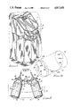
- FIG. 1 is a three-quarter front perspective view from above of a hand and forearm cleansing unit of the type utilizing this invention
- FIG. 2 is a diagrammatic plan illustration of a pair of rotatable cylinders employed in the invention
- FIG. 3 is an enlarged vertical sectional view through one of the cylinders illustrated in FIG. 2;
- FIG. 4 is a schematic illustration of one of the cylinders and certain of the cleansing fluid spray nozzles thereto;
- FIG. 5 is a fragmentary sectional view through the wall of one of the cylinders, which view is taken generally as indicated by line 5--5 in FIG. 3;
- FIG. 6 is a fragmentary elevational view of the interior of a modified hand and forearm cleansing unit.
- reference numeral 11 designates generally a free standing hand and forearm cleansing unit the components of which are housed in a cabinet 12.
- Unit 11 is the type which can be installed in a hospital or any other location where employees or occupants are required to periodically cleanse their hands.
- the cabinet 12 for unit 11 has a pair of openings 13 in the front thereof through which the hands and forearms of a user can be inserted into cleansing chambers 14 inside the cabinet Openings 13 are spaced apart a distance which is approximately the same as the distance between the elbows of a user standing before the unit and holding his hands and forearms outstretched before him. Openings 13 are also preferably positioned in surface areas 15 of the cabinet 12 which are angled back from the face of the cabinet so that the two areas 15 are at an obtuse angle with respect to each other. The result of this arrangement is that the axes of the openings 13 are at an acute angle with respect to each other to comfortably permit the entry of the hands and forearms of the user to the interior of cabinet 12.
- Cabinet 12 also has on the exterior thereof, a control center 16 at which the user selects and programs the cleansing cycle he desires.
- a control center 16 at which the user selects and programs the cleansing cycle he desires.
- the apparatus may be programmed to subject the hands and forearms to a disinfecting treatment as well.
- the apparatus may be constructed to permit the user to program the sequence and duration of the several steps.
- This invention is concerned not with any particular type of cleansing or disinfecting fluids or their sequence of application, but rather with the apparatus for and method of application of the cleansing fluid to the hands and forearms of the user.
- the invention contemplates that the cleansing fluid be sprayed onto the hands and forearms from and within a pair of rotatable cylinders which provide therein the cleansing chambers 14 (See FIGS. 2 and 3).
- Each cylinder 17 has an open, or forward, end 18 through which the hands and arms of the user can be inserted into the cleansing chamber 14 therein.
- Each cylinder 17 also preferably has its opposite, or rear, end 19 closed by a frusto-concical end closure 20.
- each cylinder 17 Disposed about the inner surface of each cylinder 17 are a plurality of spray nozzles which are adapted to spray cleansing fluid inwardly into the cleansing chamber onto the hands and forearms of the user. According to this invention, there are at least three different sets of spray nozzles in each cylinder 17 and each nozzle set has a slightly different function.
- the nozzles are identified by reference numeral 21 and function to spray cleansing fluid onto the hands and fingers of the user.
- These nozzles 21 are preferably positioned on the frusto-conical end closure 20 of each cylinder.
- Nozzles 21 are arranged to spray cleansing fluid radially inwardly of the chamber 14, and somewhat toward the open end 18 of the cylinder 17.
- Each cylinder also preferably possesses a second set of spray nozzles which are identified by reference numeral 22.
- Nozzles 22 are arranged in a ring on the inner surface of each cylinder 17 just inside the open end 18 of the cylinder.
- Nozzles 22 are arranged to spray cleansing fluid radially inwardly of the cleansing chamber 14 and slightly toward the rear end 19 of the chamber.
- the set of nozzles 22 serves as a curtain to inhibit the splashing of cleansing fluid outside the cleansing chamber 14.
- cleansing fluid sprayed by nozzles 22 impacts on the forearm of the user and supplements the cleansing action of other sprays in the chamber 14.
- the last of the preferred three sets of nozzles comprises nozzles 23 positioned on the inner surface of each cylinder 17 and extending in a helical array along the cylinder.
- the disposition of nozzles 23 can best be appreciated by reference to both FIG. 3 and the schematic illustration in FIG. 4.
- the disposition of the helical set of nozzles 23a-h is preferably coordinated with the direction of rotation of each cylinder 17 (See arrow in FIG. 4), so that the forearm and the heel portion of the hand are swept by a succession of sprays traveling from the elbow region of the forearm toward the hand.
- the direction of rotation of cylinders 17 in FIG. 4 is clockwise when viewed from the open end 18 of the cylinder
- the nozzles 23a-h are arranged in a left-hand helical pattern, or array, extending from the open end 18 to the closed end 19 of the cylinder.
- the moving sprays of this invention can be produced by merely rotating cylinders 17 and the sets of nozzles 21, 22, and 23 carried therein. Considerably less effort and energy are required to rotate cylinders 17 than to produce pulsating or varying pressure cleansing fluid jets.
- the apparatus of this invention can produce equal or better cleansing with the expenditure of less energy and with less heavy and bulky motors and other equipment than was required with prior apparatus.
- each cylinder 17 is preferably mounted with their axes at a slight angle to the horizontal, for example, approximately 10 degrees (See FIG. 3). With the open end 18 of each cylinder 17 positioned higher than the rear end 19 thereof the cleansing fluid flows by gravity toward the drain openings 24 of each cylinder.
- the frusto-conical configuration of end closures 20 of each cylinder also promotes the flow of cleansing fluid to the drain openings 24.
- the slight downward tilt to the cleansing chambers 14 occasioned by mounting cylinder 17 at an angle to the horizontal, can be easily and comfortably accommodated by the hands and forearms
- the hands and forearms can comfortably be tilted downwardly by this slight angle, particularly when the hands are closer together than the elbows as is dictated by the acute angle between the axes of the cleansing chambers 14, as mentioned previously.
- FIG. 2 The preferred relative positioning of rotatable cylinders 17 and the drive mechanism therefore, are diagrammatically illustrated in FIG. 2. It is to be noted that the axes of the cylinders 17 are disposed at an angle to each other with the open ends 18 of the cylinders being further apart than the closed ends 19 thereof.
- the angle of the displacement, indicated by the letter ⁇ , is from approximately 20 degrees to approximately 40 degrees and preferably approximately 30 degrees. This represents the comfortable disposition of the persons forearms when they are held out in the front of the body slightly above waist high and assures that a person using the cleansing unit feels comfortable in doing so. It can be readily appreciated that any discomfort experienced by the user would discourage further use of the cleansing unit and is, therefore, quietously to be avoided.
- the drive system diagrammatically illustrated in FIG. 2 comprises an electric motor 26 having a pulley 27 thereon for driving a pair of belts 28 which are looped respectively around pulleys 29 carried at the ends of cylinders 17.
- each cylinder 17 is preferably formed of an inner liner 31 and an outer liner 32. Liners 31 and 32 are joined in sealing engagement at 33 near the open end 18 of the cylinder. Liners 31 and 32 are also sealed together around each drain opening 24 as indicated at 34. Elsewhere throughout liners 31 and 32, including the closure region 20 of the cylinder 17, the liners are radially spaced apart to provide a flow passage 36 through which cleansing fluid can be conveyed to nozzles 21 and 22 and 23. Liners 31 and 32 can be mechanically joined by means of screws 37 passing through complementary end wall regions of the liner.
- Nozzles 21, 22 and 23 can be conveniently provided by drilling or casting in place openings in the inner liner 31 at appropriate locations.
- Nozzles 21, 22 and 23 can, of course, be provided by other means, such as threaded inserts (not shown) carried by the inner liner 31.
- the important consideration so far as nozzles 21, 22 and 23 are concerned is that, whatever mechanism is used to create the various sprays, that mechanism must not present any significant protruberance on the inner surface of the cylinder 17. That surface must be generally smooth so that it presents no hazard or discomfort for the hands and forearms of the user when the cylinders are rotating.
- Nozzle formed merely by drilling or casting in place openings in the inner are ideal in this respect because they present no protruberances inside the cylinder 17 and, therefore, present no hazard to the user.
- the corrugations in liner 31 are made up of short sections 38 extending inwardly and rearwardly in the cylinder 17 and relatively longer sections 39 joining the short sections and extending outwardly and rearwardly in the cylinder.
- the longer outwardly and rearwardly sloping sections 39 constitute the major portion of the inner surface area of the cylinder and tend to direct the spray splashing against the inner surface of the cylinder 17 rearwardly toward the drain openings 24 and away from the open end 18 of the cylinder This has the effect of reducing the tendency for cleansing fluid to splash out through opening 13 in the front of the cabinet.
- a further advantage to the short and long corrugation sections 38 and 39 in liner 31 lies in the longer sections 39 providing convenient locations for the nozzles 22 and 23. With nozzles 22 and 23 located on the sloping longer sections 39 the sprays therefrom (as shown by the dotted lines in FIG. 3), are directed slightly rearwardly in the cleansing chamber 14. This further reduces outsplashing of cleansing fluid from the cabinet opening 13.
- each cylinder 17 can be made to be closely spaced so as to reduce the volume of flow passage 36 to a minimum. This can be important in a cleansing unit using warm water, as most cleansing units do, because it reduces the quantity of cleansing fluid retained in the cylinders from a previous cleansing operation. That leftover fluid often will have cooled to room temperature and must be purged before an effective cleansing cycle can be commenced.
- dams 41 block and impede rotational movement of cleansing fluid in flow passage 36 in the vicinity of each of the nozzles 22 and 23.
- Some of the kinetic energy in the fluid flowing in the vicinity of a nozzle 22 or 23 is converted by the dam 41 to static energy which improves the flow of cleansing fluid into and through the nozzle thereby increasing the latter's effectiveness in producing a forceful cleaning spray.
- FIGS. 3 and 6 illustrate alternative mounting and fluid supply means.
- cleansing fluid is supplied to the cylinder 17 by means of a stationary supply conduit 42.
- Conduit 42 has a rear end portion thereof attached to a bracket 43 by adjustable clamping means 44. This portion of conduit 42 is also connected to a source of cleansing fluid (not shown). The opposite end of conduit 42 is in open communication with flow passage 36 between cylinder inner and outer liners 31 and 32.
- Outer liner 32 is preferably provided with a tubular extension 46 by which the cylinder 17 is rotatably mounted on conduit 42.
- Tubular extension 46 comprises a sealing section 47 which closely confines an elastomeric seal 48 between the extension and conduit 42. Seal 48 prevents the escape of washing fluid from cylinder 17 along the outer surface of supply conduit 42.
- Rotational support for the cylinder 17 is provided by a somewhat larger diameter bearing section 49 of extension 46 which houses bearings 51 between section 49 and conduit 42.
- Bearing section 49 of extension 46 also carries a pulley 29 by which rotational movement is imparted to cylinder 17.
- each cylinder 17 is preferably supported by a plurality of rollers 52 engaging the inner surface of the cylinder.
- FIG. 6 illustrates another mounting mode for the cylinder 17.
- the rear end of cylinder 17 is rotatably carried the stationary supply conduit 42.
- the coupling system between these components can be the same as illustrated in FIG. 3 and described above.
- the conduit 42 is mounted in an elastomeric sleeve 53 of rubber or rubber-like material which is, in turn, carried in a mounting sleeve 54 atop a bracket 55.
- each cylinder 17 is supported by a plurality of elastomeric rollers 56.
- These rollers are preferably made from metalic inner sleeves 57 having tires 58 mounted thereon.
- the tires 58 are made from rubber or other elastomeric material.
- the invention mode illustrated in FIG. 6 has one further advantageous feature associated therewith.
- This apparatus is equipped with means for further reducing the out splashing of cleansing fluid through the cabinet access openings 13.
- Both cylinders 17 (only one is shown in FIG. 6) are contained within a chamber 61 which also has a motor driven blower 62 associated therewith. Blower 62 is adapted to expel air from chamber 61. In so doing, air is drawn into chamber 61 through the open ends 18 of cylinders 17, through the cleansing chambers therein and out of the cleansing chambers through drain openings 24 into chamber 61. This flow of air into cylinders 17 inhibits the cleansing fluid spray from exiting cabinet openings 13 through the open ends of the cylinders and keeps the spray confined within the cleansing chambers 14.
- this invention provides apparatus for effectively cleansing the hands and forearms of the user.
- the apparatus has a number of features which contribute to its effectiveness while permitting the apparatus to be manufactured and operated at costs which are comparable to or less than prior apparatus intended for similar purposes.
Abstract
Description
Claims (22)
Priority Applications (1)
| Application Number | Priority Date | Filing Date | Title |
|---|---|---|---|
| US07/112,299 US4817651A (en) | 1987-10-26 | 1987-10-26 | Hand and forearm cleansing apparatus |
Applications Claiming Priority (1)
| Application Number | Priority Date | Filing Date | Title |
|---|---|---|---|
| US07/112,299 US4817651A (en) | 1987-10-26 | 1987-10-26 | Hand and forearm cleansing apparatus |
Publications (1)
| Publication Number | Publication Date |
|---|---|
| US4817651A true US4817651A (en) | 1989-04-04 |
Family
ID=22343159
Family Applications (1)
| Application Number | Title | Priority Date | Filing Date |
|---|---|---|---|
| US07/112,299 Expired - Lifetime US4817651A (en) | 1987-10-26 | 1987-10-26 | Hand and forearm cleansing apparatus |
Country Status (1)
| Country | Link |
|---|---|
| US (1) | US4817651A (en) |
Cited By (34)
| Publication number | Priority date | Publication date | Assignee | Title |
|---|---|---|---|---|
| US4909242A (en) * | 1988-05-31 | 1990-03-20 | Pacific Bio Systems, Inc. | Expandable cuff assembly for lavage machines |
| US4938933A (en) * | 1987-04-13 | 1990-07-03 | Perrot Jean J M V A | Medical and surgical instrument cleaning and disinfecting device |
| US4988485A (en) * | 1989-01-20 | 1991-01-29 | Bene Pierre Yves | Device for cleaning and disinfecting medical and surgical instruments |
| US5074322A (en) * | 1990-12-06 | 1991-12-24 | Jaw Chin Woei | Structure of sterilizing hand dryer |
| US5193563A (en) * | 1990-04-30 | 1993-03-16 | Melech Victor P | Surgical suite scrub station |
| US5265628A (en) * | 1992-06-02 | 1993-11-30 | Meritech, Inc. | Automated cleansing chamber |
| US5397028A (en) * | 1992-04-29 | 1995-03-14 | Jesadanont; Mongkol | Automatic fluid dispenser and method |
| WO1996026795A1 (en) * | 1995-02-27 | 1996-09-06 | Meritech, Inc. | Automated cleansing chamber with air knife |
| WO1997033527A1 (en) * | 1996-03-11 | 1997-09-18 | The Procter & Gamble Company | Electrostatic hand sanitizer |
| US5670945A (en) * | 1995-07-06 | 1997-09-23 | Applonie; Alan R. | Self-monitoring hand-sanitizing station |
| US5823447A (en) * | 1996-08-27 | 1998-10-20 | Meritech, Inc. | Angled fan nozzle and unibody cylinder |
| US5860437A (en) * | 1996-08-07 | 1999-01-19 | Csia Research Foundation | Self-cleaning hand washer |
| WO1999007488A1 (en) * | 1997-08-12 | 1999-02-18 | Iep Group, Inc. | Oscillating liquid jet washing system |
| US5992430A (en) * | 1998-09-28 | 1999-11-30 | 144 Limited Partnership | Automatic hand washing and drying apparatus including combined blow drying means, towel dispensing means and waste disposal means |
| WO2000018284A1 (en) | 1998-09-28 | 2000-04-06 | 144 Limited Partnership | Hand washing and drying apparatus and system including waste disposal apparatus and method |
| US6161227A (en) * | 1999-08-17 | 2000-12-19 | Bargenquast; Scott | Portable hand cleaning device |
| US6283978B1 (en) | 2000-06-09 | 2001-09-04 | Peter J. Cheski | Method and apparatus for microdermabrasion |
| US6431189B1 (en) * | 1997-06-02 | 2002-08-13 | 700303 Alberta Ltd. | Apparatus for and method of disinfecting hands |
| US6517009B2 (en) | 1997-12-25 | 2003-02-11 | Gotit Ltd. | Automatic spray dispenser |
| US20070063075A1 (en) * | 2005-09-21 | 2007-03-22 | Kaplowitz Gary H | Wound debridement apparatus |
| US7235066B1 (en) * | 2003-01-02 | 2007-06-26 | Newmedical Technology, Inc. | Fluid containment device |
| US20070160515A1 (en) * | 2006-01-09 | 2007-07-12 | Mohrman John H | Manually activated penetrating hand sterilizer |
| US20070158465A1 (en) * | 2006-01-06 | 2007-07-12 | Ingraham Frederick G | Methods for removing sand or debris from a person using a sprayer |
| US20080099049A1 (en) * | 2006-10-31 | 2008-05-01 | Icon Systems, Llc | Wash chamber for automated appendage-washing apparatus |
| US20080103636A1 (en) * | 2006-10-31 | 2008-05-01 | James Glenn | Automated Washing System With Compliance Verification And Automated Compliance Monitoring Reporting |
| US20080099043A1 (en) * | 2006-10-31 | 2008-05-01 | Icon Systems, Llc | Automated appendage cleaning apparatus with brush |
| US20080100441A1 (en) * | 2006-10-31 | 2008-05-01 | Timothy Prodanovich | Sanitizer dispensers with compliance verification |
| US20080236626A1 (en) * | 2006-11-16 | 2008-10-02 | Maybach Christopher P | Non-electric powered automatic washing apparatus |
| US20090267776A1 (en) * | 2008-04-29 | 2009-10-29 | Meritech, Inc. | Hygiene compliance |
| WO2010026284A1 (en) * | 2008-09-03 | 2010-03-11 | Handysept Oy | Automated hand-washing device |
| WO2013114096A1 (en) | 2012-01-30 | 2013-08-08 | Safeway Hygiene Services Limited | Washing device |
| US20150057620A1 (en) * | 2013-08-21 | 2015-02-26 | Jerome James Fleming | Therapy device for appendages |
| WO2016082635A1 (en) * | 2014-11-26 | 2016-06-02 | 李锋华 | Hand washing machine |
| US20170055782A1 (en) * | 2015-09-01 | 2017-03-02 | Op-Hygiene Ip Gmbh | Liquid Hand Cleaner Foam Dispensing As Spray and Liquid Stream |
Citations (12)
| Publication number | Priority date | Publication date | Assignee | Title |
|---|---|---|---|---|
| US2386455A (en) * | 1942-06-05 | 1945-10-09 | Hartford Empire Co | Liquid spray discharge apparatus for and method of cooling the interior of bottles and other hollow glass articles |
| US2769547A (en) * | 1951-06-25 | 1956-11-06 | Hirsch Abraham Adler | Articulated surface washing device with oscillatory nozzles for filter beds |
| US2826763A (en) * | 1957-02-04 | 1958-03-18 | Bass Lillian | Spray bathing apparatus with scrubbers |
| US3081471A (en) * | 1962-07-16 | 1963-03-19 | Robert E Newell | Hand washing machine |
| US3757806A (en) * | 1972-01-19 | 1973-09-11 | Us Army | Pulsating hydrojet lavage device |
| US3844278A (en) * | 1973-01-26 | 1974-10-29 | Internax Holdings Ltd | Hydrotherapeutic massage device |
| US3918987A (en) * | 1973-11-09 | 1975-11-11 | Rudolph J Kopfer | Surgeon hand and arm scrubbing apparatus |
| US4020856A (en) * | 1976-06-28 | 1977-05-03 | Masterson Albert C | Fingernail and hand cleaning appliance |
| US4219367A (en) * | 1978-10-05 | 1980-08-26 | Cary George R Jr | Surgical prep hand cleaning |
| US4402331A (en) * | 1981-03-27 | 1983-09-06 | Delta Manufacturing And Sales, Inc. | Portable lavage device |
| US4496519A (en) * | 1981-03-09 | 1985-01-29 | Mcguire Paul J | Nuclear reactor vessel decontamination systems |
| US4670010A (en) * | 1984-03-26 | 1987-06-02 | Giorgio Dragone | Liquid-nebulizing device for the dermatological treatment of the hands |
-
1987
- 1987-10-26 US US07/112,299 patent/US4817651A/en not_active Expired - Lifetime
Patent Citations (12)
| Publication number | Priority date | Publication date | Assignee | Title |
|---|---|---|---|---|
| US2386455A (en) * | 1942-06-05 | 1945-10-09 | Hartford Empire Co | Liquid spray discharge apparatus for and method of cooling the interior of bottles and other hollow glass articles |
| US2769547A (en) * | 1951-06-25 | 1956-11-06 | Hirsch Abraham Adler | Articulated surface washing device with oscillatory nozzles for filter beds |
| US2826763A (en) * | 1957-02-04 | 1958-03-18 | Bass Lillian | Spray bathing apparatus with scrubbers |
| US3081471A (en) * | 1962-07-16 | 1963-03-19 | Robert E Newell | Hand washing machine |
| US3757806A (en) * | 1972-01-19 | 1973-09-11 | Us Army | Pulsating hydrojet lavage device |
| US3844278A (en) * | 1973-01-26 | 1974-10-29 | Internax Holdings Ltd | Hydrotherapeutic massage device |
| US3918987A (en) * | 1973-11-09 | 1975-11-11 | Rudolph J Kopfer | Surgeon hand and arm scrubbing apparatus |
| US4020856A (en) * | 1976-06-28 | 1977-05-03 | Masterson Albert C | Fingernail and hand cleaning appliance |
| US4219367A (en) * | 1978-10-05 | 1980-08-26 | Cary George R Jr | Surgical prep hand cleaning |
| US4496519A (en) * | 1981-03-09 | 1985-01-29 | Mcguire Paul J | Nuclear reactor vessel decontamination systems |
| US4402331A (en) * | 1981-03-27 | 1983-09-06 | Delta Manufacturing And Sales, Inc. | Portable lavage device |
| US4670010A (en) * | 1984-03-26 | 1987-06-02 | Giorgio Dragone | Liquid-nebulizing device for the dermatological treatment of the hands |
Cited By (87)
| Publication number | Priority date | Publication date | Assignee | Title |
|---|---|---|---|---|
| US4938933A (en) * | 1987-04-13 | 1990-07-03 | Perrot Jean J M V A | Medical and surgical instrument cleaning and disinfecting device |
| US4909242A (en) * | 1988-05-31 | 1990-03-20 | Pacific Bio Systems, Inc. | Expandable cuff assembly for lavage machines |
| US4988485A (en) * | 1989-01-20 | 1991-01-29 | Bene Pierre Yves | Device for cleaning and disinfecting medical and surgical instruments |
| AU619377B2 (en) * | 1989-01-20 | 1992-01-23 | Pierre-Yves Bene | Device for cleaning and disinfecting medical and surgical instruments |
| US5193563A (en) * | 1990-04-30 | 1993-03-16 | Melech Victor P | Surgical suite scrub station |
| US5074322A (en) * | 1990-12-06 | 1991-12-24 | Jaw Chin Woei | Structure of sterilizing hand dryer |
| US5397028A (en) * | 1992-04-29 | 1995-03-14 | Jesadanont; Mongkol | Automatic fluid dispenser and method |
| US5265628A (en) * | 1992-06-02 | 1993-11-30 | Meritech, Inc. | Automated cleansing chamber |
| WO1996026795A1 (en) * | 1995-02-27 | 1996-09-06 | Meritech, Inc. | Automated cleansing chamber with air knife |
| US5670945A (en) * | 1995-07-06 | 1997-09-23 | Applonie; Alan R. | Self-monitoring hand-sanitizing station |
| WO1997033527A1 (en) * | 1996-03-11 | 1997-09-18 | The Procter & Gamble Company | Electrostatic hand sanitizer |
| US5972126A (en) * | 1996-08-07 | 1999-10-26 | Sunnybrook & Women's College Health Sciences Centre | Self-cleaning hand washer |
| US5860437A (en) * | 1996-08-07 | 1999-01-19 | Csia Research Foundation | Self-cleaning hand washer |
| US5823447A (en) * | 1996-08-27 | 1998-10-20 | Meritech, Inc. | Angled fan nozzle and unibody cylinder |
| US6431189B1 (en) * | 1997-06-02 | 2002-08-13 | 700303 Alberta Ltd. | Apparatus for and method of disinfecting hands |
| US6176941B1 (en) * | 1997-08-12 | 2001-01-23 | Warren R. Jewett | Method of removing contaminants from an epidermal surface using an oscillating fluidic spray |
| WO1999007488A1 (en) * | 1997-08-12 | 1999-02-18 | Iep Group, Inc. | Oscillating liquid jet washing system |
| US6110292A (en) * | 1997-08-12 | 2000-08-29 | Warren R. Jewett | Oscillating liquid jet washing system |
| US6540155B1 (en) | 1997-12-25 | 2003-04-01 | Gotit Ltd. | Automatic spray dispenser |
| US6517009B2 (en) | 1997-12-25 | 2003-02-11 | Gotit Ltd. | Automatic spray dispenser |
| US6131587A (en) * | 1998-09-28 | 2000-10-17 | 144 Limited Partnership | Hand washing and drying apparatus and system including waste disposal apparatus and method |
| WO2000018284A1 (en) | 1998-09-28 | 2000-04-06 | 144 Limited Partnership | Hand washing and drying apparatus and system including waste disposal apparatus and method |
| US5992430A (en) * | 1998-09-28 | 1999-11-30 | 144 Limited Partnership | Automatic hand washing and drying apparatus including combined blow drying means, towel dispensing means and waste disposal means |
| US6161227A (en) * | 1999-08-17 | 2000-12-19 | Bargenquast; Scott | Portable hand cleaning device |
| US6283978B1 (en) | 2000-06-09 | 2001-09-04 | Peter J. Cheski | Method and apparatus for microdermabrasion |
| US7235066B1 (en) * | 2003-01-02 | 2007-06-26 | Newmedical Technology, Inc. | Fluid containment device |
| US20070063075A1 (en) * | 2005-09-21 | 2007-03-22 | Kaplowitz Gary H | Wound debridement apparatus |
| US20070158465A1 (en) * | 2006-01-06 | 2007-07-12 | Ingraham Frederick G | Methods for removing sand or debris from a person using a sprayer |
| US20070160515A1 (en) * | 2006-01-09 | 2007-07-12 | Mohrman John H | Manually activated penetrating hand sterilizer |
| US20090084417A1 (en) * | 2006-10-31 | 2009-04-02 | Barnhill Paul R | Wash chamber for automated appendage-washing apparatus |
| US7698770B2 (en) | 2006-10-31 | 2010-04-20 | Resurgent Health & Medical, Llc | Automated appendage cleaning apparatus with brush |
| US20080103636A1 (en) * | 2006-10-31 | 2008-05-01 | James Glenn | Automated Washing System With Compliance Verification And Automated Compliance Monitoring Reporting |
| US20080099048A1 (en) * | 2006-10-31 | 2008-05-01 | Icon Systems, Llc | Wash chamber for automated appendage-washing apparatus |
| US20080099050A1 (en) * | 2006-10-31 | 2008-05-01 | Icon Systems, Llc | Wash chamber for automated appendage-washing apparatus |
| US20080099043A1 (en) * | 2006-10-31 | 2008-05-01 | Icon Systems, Llc | Automated appendage cleaning apparatus with brush |
| US20080100441A1 (en) * | 2006-10-31 | 2008-05-01 | Timothy Prodanovich | Sanitizer dispensers with compliance verification |
| WO2008054907A2 (en) * | 2006-10-31 | 2008-05-08 | Icon Systems, Llc | Wash chamber for automated appendage-washing apparatus |
| US8110047B2 (en) | 2006-10-31 | 2012-02-07 | Resurgent Health & Medical, Llc | Automated washing system with compliance verification |
| WO2008054907A3 (en) * | 2006-10-31 | 2008-10-23 | Icon Systems Llc | Wash chamber for automated appendage-washing apparatus |
| US20090084414A1 (en) * | 2006-10-31 | 2009-04-02 | Barnhill Paul R | Wash chamber for automated appendage-washing apparatus |
| US20090083970A1 (en) * | 2006-10-31 | 2009-04-02 | Barnhill Paul R | Wash chamber for automated appendage washing apparatus |
| US20090084407A1 (en) * | 2006-10-31 | 2009-04-02 | James Glenn | Automated washing system with compliance verification |
| US20080099049A1 (en) * | 2006-10-31 | 2008-05-01 | Icon Systems, Llc | Wash chamber for automated appendage-washing apparatus |
| US20090090389A1 (en) * | 2006-10-31 | 2009-04-09 | Barnhill Paul R | Wash chamber for automated appendage-washing apparatus |
| US20090094814A1 (en) * | 2006-10-31 | 2009-04-16 | Barnhill Paul R | Wash chamber for automated appendage-washing apparatus |
| EP2086696A2 (en) * | 2006-10-31 | 2009-08-12 | Icon Systems, LLC | Wash chamber for automated appendage-washing apparatus |
| US7607442B2 (en) | 2006-10-31 | 2009-10-27 | Resurgent Health & Medical, Llc | Wash chamber for automated appendage-washing apparatus |
| US7607443B2 (en) * | 2006-10-31 | 2009-10-27 | Resurgent Health & Medical, Llc | Wash chamber for automated appendage-washing apparatus |
| US8085155B2 (en) | 2006-10-31 | 2011-12-27 | Resurgent Health & Medical, Llc | Sanitizer dispensers with compliance verification |
| EP2086696A4 (en) * | 2006-10-31 | 2011-12-21 | Resurgent Health & Medical Llc | Wash chamber for automated appendage-washing apparatus |
| US20110247665A1 (en) * | 2006-10-31 | 2011-10-13 | Resurgent Health & Medical, Llc | Wash chamber for automated appendage-washing apparatus |
| US7617830B2 (en) | 2006-10-31 | 2009-11-17 | Resurgent Health & Medical, Llc | Wash chamber for automated appendage-washing apparatus |
| US7993471B2 (en) * | 2006-10-31 | 2011-08-09 | Barnhill Paul R | Wash chamber for automated appendage-washing apparatus |
| US7901513B2 (en) | 2006-10-31 | 2011-03-08 | Resurgent Health & Medical, LLC. | Wash chamber for appendage-washing method |
| US7641740B2 (en) * | 2006-10-31 | 2010-01-05 | Resurgent Health & Medical, Llc | Wash chamber for automated appendage-washing apparatus |
| US7659824B2 (en) | 2006-10-31 | 2010-02-09 | Resurgent Health & Medical, Llc | Sanitizer dispensers with compliance verification |
| US7883585B2 (en) | 2006-10-31 | 2011-02-08 | Resurgent Health & Medical, Llc | Wash chamber for appendage-washing method |
| US7682464B2 (en) | 2006-10-31 | 2010-03-23 | Resurgent Health & Medical, Llc | Automated washing system with compliance verification |
| US20080099047A1 (en) * | 2006-10-31 | 2008-05-01 | Icon Systems, Llc | Wash chamber for automated appendage-washing apparatus |
| US20100097224A1 (en) * | 2006-10-31 | 2010-04-22 | Resurgent Health & Medical, Llc | Sanitizer dispensers with compliance verification |
| US7754022B2 (en) | 2006-10-31 | 2010-07-13 | Resurgent Health & Medical, Llc | Wash chamber for appendage-washing method |
| US7754021B2 (en) | 2006-10-31 | 2010-07-13 | Resurgent Health & Medical, Llc | Wash chamber for appendage-washing apparatus |
| US7758701B2 (en) | 2006-10-31 | 2010-07-20 | Resurgent Health & Medical, Llc | Wash chamber for automated appendage-washing apparatus |
| US7757700B2 (en) * | 2006-10-31 | 2010-07-20 | Resurgent Health & Medical, Llc | Wash chamber for automated appendage-washing apparatus |
| US7789095B2 (en) | 2006-10-31 | 2010-09-07 | Resurgent Health & Medical, Llc | Wash chamber for automated appendage-washing apparatus |
| US7818083B2 (en) | 2006-10-31 | 2010-10-19 | Resurgent Health & Medical, Llc | Automated washing system with compliance verification and automated compliance monitoring reporting |
| US20100313916A1 (en) * | 2006-10-31 | 2010-12-16 | Resurgent Health & Medical, Llc | Wash chamber for appendage-washing apparatus |
| US20080236626A1 (en) * | 2006-11-16 | 2008-10-02 | Maybach Christopher P | Non-electric powered automatic washing apparatus |
| US8294585B2 (en) | 2008-04-29 | 2012-10-23 | Resurgent Health & Medical, Llc | Complete hand care |
| US8146613B2 (en) * | 2008-04-29 | 2012-04-03 | Resurgent Health & Medical, Llc | Wash chamber for surgical environment |
| US20090272405A1 (en) * | 2008-04-29 | 2009-11-05 | Meritech, Inc. | Ingress/egress system for hygiene compliance |
| US20090273477A1 (en) * | 2008-04-29 | 2009-11-05 | Meritech, Inc. | Hygiene compliance monitoring |
| US20090267776A1 (en) * | 2008-04-29 | 2009-10-29 | Meritech, Inc. | Hygiene compliance |
| US20090301523A1 (en) * | 2008-04-29 | 2009-12-10 | Meritech, Inc. | Wash Chamber for Surgical Environment |
| US20090299787A1 (en) * | 2008-04-29 | 2009-12-03 | Meritech, Inc. | Complete hand care |
| US8400309B2 (en) | 2008-04-29 | 2013-03-19 | Resurgent Health & Medical, Llc | Hygiene compliance |
| US8377229B2 (en) | 2008-04-29 | 2013-02-19 | Resurgent Health & Medical, Llc | Ingress/egress system for hygiene compliance |
| US20110174348A1 (en) * | 2008-09-03 | 2011-07-21 | Handysept Oy | Automated hand-washing device |
| CN102202696A (en) * | 2008-09-03 | 2011-09-28 | 翰迪赛普特有限公司 | Automated hand-washing device |
| WO2010026284A1 (en) * | 2008-09-03 | 2010-03-11 | Handysept Oy | Automated hand-washing device |
| WO2013114096A1 (en) | 2012-01-30 | 2013-08-08 | Safeway Hygiene Services Limited | Washing device |
| US20150057620A1 (en) * | 2013-08-21 | 2015-02-26 | Jerome James Fleming | Therapy device for appendages |
| US9649221B2 (en) * | 2013-08-21 | 2017-05-16 | Jerome James Fleming | Therapy device for appendages |
| WO2016082635A1 (en) * | 2014-11-26 | 2016-06-02 | 李锋华 | Hand washing machine |
| US20170055782A1 (en) * | 2015-09-01 | 2017-03-02 | Op-Hygiene Ip Gmbh | Liquid Hand Cleaner Foam Dispensing As Spray and Liquid Stream |
| US10238241B2 (en) * | 2015-09-01 | 2019-03-26 | Op-Hygiene Ip Gmbh | Liquid hand cleaner foam dispensing as spray and liquid stream |
| US10617263B2 (en) | 2015-09-01 | 2020-04-14 | Op-Hygiene Ip Gmbh | Liquid hand cleaner foam dispensing as spray and liquid stream |
Similar Documents
| Publication | Publication Date | Title |
|---|---|---|
| US4817651A (en) | Hand and forearm cleansing apparatus | |
| CA1206067A (en) | Portable lavage device | |
| WO2016082635A1 (en) | Hand washing machine | |
| CA2041087A1 (en) | Surgical suite scrub station | |
| US4802508A (en) | Cyclically varying pulsating fluid supply system | |
| US4465522A (en) | Method for surgically cleaning hands and arms | |
| US8978175B2 (en) | Variable position shower apparatus and related methods | |
| US5241953A (en) | Fluid pressure massage system | |
| CN100400022C (en) | Vacuum massage device comprising the affusion of water or any other suitable liquid | |
| JP3129114U (en) | Body washing device | |
| US8419667B2 (en) | Electric shower masseuse | |
| US20050203447A1 (en) | Waterproof hydrotherapy limb massager | |
| JPH09262512A (en) | Gas-liquid jetting machine and its operation method | |
| EP0086834A1 (en) | Surgical scrubbing device | |
| CN213852391U (en) | Orthopedic motion wound and arthroscopic surgery are with treatment auxiliary device | |
| CN211247650U (en) | Inner sleeve cleaning device for disinfection supply room | |
| KR101940639B1 (en) | A suit for body bath | |
| KR100680806B1 (en) | Apparatus for a sitz bath | |
| CN219289308U (en) | Full-automatic multifunctional whole body washing and protecting integrated machine | |
| JPH0135647B2 (en) | ||
| CN218738616U (en) | Automatic disinfection hand washing instrument | |
| CN219166252U (en) | Intelligent bath rubbing machine | |
| JPS58159748A (en) | Apparatus for washing patient | |
| CN117243806A (en) | Traditional Chinese medicine fumigation treatment device for rheumatism immunology department | |
| JPH04166152A (en) | Sucking beauty apparatus |
Legal Events
| Date | Code | Title | Description |
|---|---|---|---|
| AS | Assignment |
Owner name: SCIENTIFIC GROWTH, INC., A ARIZONA CORP.,ARIZONA Free format text: ASSIGNMENT OF ASSIGNORS INTEREST;ASSIGNORS:CRISP, WILLIAM E.;KUDLICKI, RICHARD C.;SMITH, JUDSON L.;SIGNING DATES FROM 19871006 TO 19871021;REEL/FRAME:004782/0071 Owner name: SCIENTIFIC GROWTH, INC., 5030 SOUTH MILL, C-1 TEMP Free format text: ASSIGNMENT OF ASSIGNORS INTEREST.;ASSIGNORS:CRISP, WILLIAM E.;KUDLICKI, RICHARD C.;SMITH, JUDSON L.;REEL/FRAME:004782/0071;SIGNING DATES FROM 19871006 TO 19871021 |
|
| STCF | Information on status: patent grant |
Free format text: PATENTED CASE |
|
| FEPP | Fee payment procedure |
Free format text: PAYOR NUMBER ASSIGNED (ORIGINAL EVENT CODE: ASPN); ENTITY STATUS OF PATENT OWNER: SMALL ENTITY |
|
| FPAY | Fee payment |
Year of fee payment: 4 |
|
| AS | Assignment |
Owner name: MERITECH, INC., COLORADO Free format text: ASSIGNMENT OF ASSIGNORS INTEREST;ASSIGNOR:SCIENTIFIC GROWTH, INC.;REEL/FRAME:006559/0317 Effective date: 19890203 |
|
| FPAY | Fee payment |
Year of fee payment: 8 |
|
| FEPP | Fee payment procedure |
Free format text: PAYOR NUMBER ASSIGNED (ORIGINAL EVENT CODE: ASPN); ENTITY STATUS OF PATENT OWNER: SMALL ENTITY Free format text: PAYER NUMBER DE-ASSIGNED (ORIGINAL EVENT CODE: RMPN); ENTITY STATUS OF PATENT OWNER: SMALL ENTITY |
|
| FPAY | Fee payment |
Year of fee payment: 12 |
|
| AS | Assignment |
Owner name: NEW MERITECH, INC., COLORADO Free format text: MERGER;ASSIGNOR:MERITECH, INC.;REEL/FRAME:017626/0708 Effective date: 20001219 Owner name: MERITECH, INC., COLORADO Free format text: CHANGE OF NAME;ASSIGNOR:NEW MERITECH, INC.;REEL/FRAME:017626/0742 Effective date: 20020212 |
|
| AS | Assignment |
Owner name: ICON SYSTEMS, LLC, COLORADO Free format text: ASSIGNMENT OF ASSIGNORS INTEREST;ASSIGNOR:MERITECH, INC.;REEL/FRAME:018120/0674 Effective date: 20060815 |