US4818320A - Nasal cannula harness and method of making the same - Google Patents
Nasal cannula harness and method of making the same Download PDFInfo
- Publication number
- US4818320A US4818320A US06/882,046 US88204686A US4818320A US 4818320 A US4818320 A US 4818320A US 88204686 A US88204686 A US 88204686A US 4818320 A US4818320 A US 4818320A
- Authority
- US
- United States
- Prior art keywords
- sheet
- tubes
- channels
- narine
- members
- Prior art date
- Legal status (The legal status is an assumption and is not a legal conclusion. Google has not performed a legal analysis and makes no representation as to the accuracy of the status listed.)
- Expired - Lifetime
Links
Images


Classifications
-
- A—HUMAN NECESSITIES
- A61—MEDICAL OR VETERINARY SCIENCE; HYGIENE
- A61M—DEVICES FOR INTRODUCING MEDIA INTO, OR ONTO, THE BODY; DEVICES FOR TRANSDUCING BODY MEDIA OR FOR TAKING MEDIA FROM THE BODY; DEVICES FOR PRODUCING OR ENDING SLEEP OR STUPOR
- A61M16/00—Devices for influencing the respiratory system of patients by gas treatment, e.g. mouth-to-mouth respiration; Tracheal tubes
- A61M16/06—Respiratory or anaesthetic masks
- A61M16/0666—Nasal cannulas or tubing
-
- Y—GENERAL TAGGING OF NEW TECHNOLOGICAL DEVELOPMENTS; GENERAL TAGGING OF CROSS-SECTIONAL TECHNOLOGIES SPANNING OVER SEVERAL SECTIONS OF THE IPC; TECHNICAL SUBJECTS COVERED BY FORMER USPC CROSS-REFERENCE ART COLLECTIONS [XRACs] AND DIGESTS
- Y10—TECHNICAL SUBJECTS COVERED BY FORMER USPC
- Y10S—TECHNICAL SUBJECTS COVERED BY FORMER USPC CROSS-REFERENCE ART COLLECTIONS [XRACs] AND DIGESTS
- Y10S128/00—Surgery
- Y10S128/26—Cannula supporters
-
- Y—GENERAL TAGGING OF NEW TECHNOLOGICAL DEVELOPMENTS; GENERAL TAGGING OF CROSS-SECTIONAL TECHNOLOGIES SPANNING OVER SEVERAL SECTIONS OF THE IPC; TECHNICAL SUBJECTS COVERED BY FORMER USPC CROSS-REFERENCE ART COLLECTIONS [XRACs] AND DIGESTS
- Y10—TECHNICAL SUBJECTS COVERED BY FORMER USPC
- Y10T—TECHNICAL SUBJECTS COVERED BY FORMER US CLASSIFICATION
- Y10T156/00—Adhesive bonding and miscellaneous chemical manufacture
- Y10T156/10—Methods of surface bonding and/or assembly therefor
- Y10T156/1002—Methods of surface bonding and/or assembly therefor with permanent bending or reshaping or surface deformation of self sustaining lamina
- Y10T156/1028—Methods of surface bonding and/or assembly therefor with permanent bending or reshaping or surface deformation of self sustaining lamina by bending, drawing or stretch forming sheet to assume shape of configured lamina while in contact therewith
- Y10T156/1033—Flexible sheet to cylinder lamina
-
- Y—GENERAL TAGGING OF NEW TECHNOLOGICAL DEVELOPMENTS; GENERAL TAGGING OF CROSS-SECTIONAL TECHNOLOGIES SPANNING OVER SEVERAL SECTIONS OF THE IPC; TECHNICAL SUBJECTS COVERED BY FORMER USPC CROSS-REFERENCE ART COLLECTIONS [XRACs] AND DIGESTS
- Y10—TECHNICAL SUBJECTS COVERED BY FORMER USPC
- Y10T—TECHNICAL SUBJECTS COVERED BY FORMER US CLASSIFICATION
- Y10T156/00—Adhesive bonding and miscellaneous chemical manufacture
- Y10T156/10—Methods of surface bonding and/or assembly therefor
- Y10T156/1002—Methods of surface bonding and/or assembly therefor with permanent bending or reshaping or surface deformation of self sustaining lamina
- Y10T156/1051—Methods of surface bonding and/or assembly therefor with permanent bending or reshaping or surface deformation of self sustaining lamina by folding
Definitions
- This invention relates to nasal cannula harnesses for supplying gas to the nasal passages of a patient and to the method of making the same.
- a nasal cannual may include a hollow molded bridge member having integrally molded narine tubes and with the bridge member conected to a pair of gas supply tubes.
- Such hollow bridge members are relatively expensive to mold.
- narine tubes are inserted through holes in a tubular bridge member. With the latter type of bridge, the narine tubes are generally not securely held against relative movement and bending so that there is a possibility that administration gas may be interupted if a tube becomes bent in use. Also, such a tubular bridge member may become so flexible that the narine tubes are difficult to manage or be inserted and maintained within the nares of the patient.
- Another object is to provide a nasal cannula having an improved bridge for the narine tubes and to an improved method of making the same, and which is simple and economical in construction, and which provides good support for the narine tubes.
- a nasal cannula harness which includes a pair of sheet members secured together in facing relation with a pair of narine tubes extending between the sheet members and from one side thereof, the tubes being adapted for insertion into the nares of a patient.
- a pair of narine tubes are positioned between a pair of sheet members and the sheets members are clamped and secured together in areas on each side of the tubes.
- a first section of a sheet member is provided with channels for receiving and locating a pair of narine tubes, and a second section of the sheet member is folded over the tubes and secured in facing relation with the first section to secure the narine tubes between the sections.
- FIG. 1 is a plan view of a nasal cannula harness assembly in accordance with a preferred embodiment of the present invention
- FIG. 2 is a prospective view on an enlarged scale of the nasal cannula of FIG. 1;
- FIG. 3 is a plan view on an enlarged scale of a molded sheet member used in making the nasal cannula of FIG. 1;
- FIG. 4 is a bottom side view of the sheet member of FIG. 3;
- FIG. 5 is a right end view of the sheet member of FIG. 3;
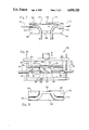
- FIG. 6 is a cross-sectional view taken along the line 6--6 of FIG. 3;
- FIG. 7 illustrates a step in the manufacture of the nasal cannula of FIG. 1;
- FIG. 8 shows a clamping die assembly which may be used in the manufacture of the nasal cannula of FIG. 1;
- FIG. 9 is a bottom plan view of the upper die member of the clamping die of FIG. 9.
- a nasal cannual harness assembly 10 including a nasal cannual harness 12 connected through a tube connector 14 to a main gas supply tube 16 which, in turn, is adapted for connection to a source of gas 18, for example, a source of oxygen or other suitable therapeutic gas.
- the nasal cannula harness 12 is shown including a nasal cannula 19, a pair of narine gas supply tubes 20 and 22, and a slip ring 23.
- the narine tubes have proximal end portions 24 and 26, respectively, connected in sealing relation in a pair of openings extending through a resilient connector plug member 28 of connector 14.
- Plug 28 may be of rubber or plastic and is shown in fluid tight connection within the distal end of gas supply tube 16.
- Tube 16 has a greater inner diameter than either of the narine tubes 20 and 22 so as to provide sufficient flow of gas to the nasal cannula harness 12.
- the nasal cannula 19 includes a bridge 30 connecting distal end portions 31 and 32 of the narine tubes 20 and 22, respectively, in predetermined relationship.
- the distal end portions 31 and 32 of the narine tubes 20 and 22 extend into the opposed ends 34 and 36, respectively, of the bridge 30 and smoothly curve upwardly to and beyond the upper side 38 of the bridge.
- the end portions 31 and 32 have external end portions or extensions indicated at 40 and 42, respectively, that are adapted to be received in the nares of a patient.
- the nare receiving extensions 40 and 42 extend approximately parallel to each other and are shown provided with smoothly rounded, radially outwardly extending rings or flanges 44 and 46, respectively, at the distal ends thereof and provide a desirable fit within the nares of patient when the nasal harness 12 is in use.
- the bridge 30 is preferably formed from a unitary or single-piece molded sheet member 48 which is folded back upon itself to provide a pair of facing sheet members or sections 50 and 52 although it is possible to use separate sheet members.
- the distal end portions 31 and 32 of the narine tubes are clamped between the sheet sections 50 and 52 with the sheet sections secured to one another in areas on opposed sides of each of the tube end portions 31 and 32.
- the sheet member 48 may be made of rubber or other plastic and is preferably formed of a flexible plastic such as polyvinyl chloride, polyehtylene, or other suitable thermoplastic material.
- the sheet member 48 is shown prior to its assembly with the narine tubes in FIGS. 3-7.
- Member 48 has a longitudinally extending fold groove 54 providing a hinge extending from the left end to the right end of the sheet member, as viewed in FIG. 7, which divides the member into sheet sections 50 and 52.
- the groove 54 facilitates folding of the sheet member 48 about the narine tubes.
- sheet section 50 has a pair of grooves or channels 56 and 58 formed in its inner side which extend inwardly from the left and right ends, respectively, of the section and then smoothly curve upwardly to the upper edge of the section.
- Section 52 also has a pair of grooves or channels indicated at 60 and 62 which extend inwardly from the left and right ends of the section, respectively, and smoothly curve downwardly to the lower edge of the section.
- the left ends of channels 56 and 60 and the right ends of the chanels 58 and 62 are adjacent the fold groove 54.
- the sheet member 48 is shown having a substantially constant thickness throughout except at the fold groove 54 and in areas between the channels and adjacent the upper and lower edges of the sheet member. As seen best in FIGS. 3, 4, 6 and 7, the sheet member is provided with a rounded thickened portion 64 extending longitudinally adjacent the upper edge of the sheet member between the channels 56 and 58. Also, a similar rounded thickened portion 66 is shown extending longitudinally adjacent the lower edge of the sheet member between channels 60 and 62. The rounded portions 64 and 66 in the finished bridge shown in FIG. 2, provide a smoothly rounded nose rest 68 which generally engages the nose of the patient when the harness 12 is in use.
- the distal end portions 31 and 32 may be inserted, for example, into the channels 60 and 62 of sheet member section 52 as shown in FIG. 7.
- the sheet member 48 is shown partially folded about groove 54 with the upper section 50 at 90° to the section 52.
- the sheet section 50 may be further folded along fold groove 54 and over the tube sections 31 and 32 with the engaging surfaces or a substantial area thereof secured to the complementary surface of the sheet section 52 to form the assembly as shown in FIGS. 1 and 2.
- Surfaces of the sheet sections may be secured together (depending upon the material used) by heat welding, solvent bonding, cementing or in other suitable ways.
- the channels 56 and 60 are complementary and form a tunnel 70 in the bridge (FIG. 2) through which the distal end portion 31 of tube 20 extends, and the complementary channels 58 and 62 form a tunnel 72 through the bridge 30 and through which the distal end portion 32 of narine tube 22 extends.
- a heat welding die assembly 74 of FIG. 8 may be used.
- the die assembly 77 includes upper and lower die members 76 and 78 adapted to be heated and which have facing surfaces that are mirror images of each other.
- the upper die member 76 as shown in FIG. 9, includes a pair of channels 80 and 81 generally complementary to and which receive the channels 56 and 58 of the sheet section 50 during assembly.
- the die channels 80 and 81 are connected by a longitudinally extending channel or recess indicated at 82 which is complementary to and is adapted to receive the rounded longitudinally extending portion 64 of sheet section 50.
- the bottom face of die member 76 also has flat heat sealing or welding portions 83, 84 and 85 adapted to engage the flat portions of sheet section 50 during welding.
- the lower die member 78 includes die channels 86 and 88 for receiving channels 60 and 62 of section 52 and it has a longitudinally extending recess 90 which accommodates rounded portion 66 of the sheet section 52.
- Die member 78 also has flat heat welding areas 91, 93 and 95 which engage flat portions of sheet section 52 and are complementary to and cooperate with areas 83, 84 and 85 of die member 76 to weld the sections 50 and 52 together.
- the distal end portions 31 and 32 of the narine tubes may be inserted into the channels 60 and 62 of sheet section 52 as indicated in FIG. 7.
- the sheet section 50 may be further folded along the fold groove 54 until it forms an acute angle with the sheet section 52. This may be done in the die assembly in some cases, or a partially folded sheet member 48 may be inserted into the lower die member 78 with the channels 60 and 62 of section 52 inserted into channels 86 and 88 of the lower die member 78 as shown in FIG. 8.
- the channels in the upper and lower die members receive the complementary channels of the sheet member 48, and the rounded portions 64 and 66 are respectively received in channels 82 and 90 of the die members.
- the welding portion 83, 84 and 85 of the upper die 76 cooperate respectively with welding portions 91, 92 and 93 of lower die member 78 to engage and heat seal or weld the facing flat areas of the sheet sections together to form the flat portions 92, 94 and 96 (FIG. 2) of the finished bridge 30.
- the flat welded portions 92, 94 and 96 of the bridge 30 maintain the tubes securely located in the tunnels 70 and 72.
- the tunnels 70 and 72 are sized relative to the size of the narine tubes such that the inner sidewalls of the tunnels frictionally engage the outer surfaces of the tube portions 31 and 32 to maintain them in fixed relationship with the bridge 30. In this way, it is generally not necessary to effect a heat or other bond between the outer surface of the narine tubes 20 and 22 and the inner surfaces of the tunnels 70 and 72 in order to prevent relative movement between the tubes and bridge.
- Die assembly 74 may be used, instead of using heat welding, to solvent bond or cement the flat facing surfaces together. Where welding is employed, well known ultrahigh frequency or radio frequency welding may be employed to assemble the bridged and tubes. The inner flat facing sides of the portions 64 and 66 that form the nose rest 68 may also be fixed together.
- the two narine tube extensions 40 and 42 are inserted into the nares of the patient with the tubes 20 and 22 generally extending over and behind the ears and downwardly to a point below the chin.
- the slip ring 23 may be adjusted to provide a desirable harness fit.
- the sheet sections of the bridge 30 may be easily and economically molded from flat plastic sheet stock.
- the bridges are especially economically and simple to make when the bridge sections are of a single unitary molded part such as shown for illustration in the drawings.
- the assembling of the narine tubes 20 and 22 with the sheet member 48 is simple and economical to perform.
- the narine tubes in the finished harness are firmly held in the desired location by the tunnels 70 and 72.
- the sheet member channels forming the tunnels facilitate the manufacture of the nasal cannula harness since the narine tubes may be easily manually bent or curved to fit within the channels.
- the channels readily predeterminately shape and maintain the distal end portions of the narine tubes in a desired configuration during assembly.
- sheet members having preformed channels such as sheet members 50 and 52
- a pair of sheet members in which there are no preformed channels or where only one of the sheet members is preformed with a pair of channels can be used.
- the tubes can be readily located during manufacture; however, the tubes may be held in the shown desired location by any suitable means and unchanneled members used.
- the narine tubes 20 and 22, the slip ring 23, and supply tube 16 may be made of any suitable rubber or plastic. For example, they may be extruded from polyvinyl chloride or polyethylene.
Abstract
Description
Claims (10)
Priority Applications (1)
| Application Number | Priority Date | Filing Date | Title |
|---|---|---|---|
| US06/882,046 US4818320A (en) | 1984-04-04 | 1986-07-03 | Nasal cannula harness and method of making the same |
Applications Claiming Priority (2)
| Application Number | Priority Date | Filing Date | Title |
|---|---|---|---|
| US06/596,754 US4790308A (en) | 1984-04-04 | 1984-04-04 | Nasal cannula harness |
| US06/882,046 US4818320A (en) | 1984-04-04 | 1986-07-03 | Nasal cannula harness and method of making the same |
Related Parent Applications (1)
| Application Number | Title | Priority Date | Filing Date |
|---|---|---|---|
| US06/596,754 Division US4790308A (en) | 1984-04-04 | 1984-04-04 | Nasal cannula harness |
Publications (1)
| Publication Number | Publication Date |
|---|---|
| US4818320A true US4818320A (en) | 1989-04-04 |
Family
ID=27082616
Family Applications (1)
| Application Number | Title | Priority Date | Filing Date |
|---|---|---|---|
| US06/882,046 Expired - Lifetime US4818320A (en) | 1984-04-04 | 1986-07-03 | Nasal cannula harness and method of making the same |
Country Status (1)
| Country | Link |
|---|---|
| US (1) | US4818320A (en) |
Cited By (56)
| Publication number | Priority date | Publication date | Assignee | Title |
|---|---|---|---|---|
| US5269296A (en) * | 1991-10-29 | 1993-12-14 | Landis Robert M | Nasal continuous positive airway pressure apparatus and method |
| US5389177A (en) * | 1990-10-31 | 1995-02-14 | Shuert; Lyle H. | Thermoforming process for making a twin sheet plastic structure including captured metallic element |
| US5477852A (en) * | 1991-10-29 | 1995-12-26 | Airways Ltd., Inc. | Nasal positive airway pressure apparatus and method |
| US5509409A (en) * | 1994-09-12 | 1996-04-23 | The Living Trust Of Marjorie F. Weatherholt | Nasal cannula assembly |
| USD378313S (en) * | 1995-04-24 | 1997-03-04 | Doyle Donald E | Spacer - septal splint |
| US5657752A (en) * | 1996-03-28 | 1997-08-19 | Airways Associates | Nasal positive airway pressure mask and method |
| US5682881A (en) * | 1996-10-21 | 1997-11-04 | Winthrop; Neil | Nasal CPAP/Cannula and securement apparatus |
| US5687715A (en) * | 1991-10-29 | 1997-11-18 | Airways Ltd Inc | Nasal positive airway pressure apparatus and method |
| US5983898A (en) * | 1997-04-30 | 1999-11-16 | Doyle; Donald E. | Airway splint obturator |
| USD422699S (en) * | 1998-02-28 | 2000-04-11 | The Living Trust Of Marjorie F. Weatherholt | Flexible pad for nasal cannula |
| US20030030183A1 (en) * | 2001-01-04 | 2003-02-13 | Curti James N. | Nasal and oral cannula breathing detection devices |
| US6533983B2 (en) * | 2001-01-04 | 2003-03-18 | Salter Labs | Method to produce nasal and oral cannula apnea detection devices |
| US20030111081A1 (en) * | 2001-12-19 | 2003-06-19 | Gupta Parshotam C. | Detachable nasal cannula assembly |
| US20040020493A1 (en) * | 2000-03-13 | 2004-02-05 | Wood Thomas J. | Ventilation interface for sleep apnea therapy |
| US20040112383A1 (en) * | 2001-01-04 | 2004-06-17 | Curti James N. | Nasal and oral cannula breathing detection device |
| US6805126B2 (en) * | 1998-12-01 | 2004-10-19 | Edward P. Dutkiewicz | Oxygen delivery and gas sensing nasal cannula system |
| US20040221846A1 (en) * | 2001-01-04 | 2004-11-11 | Curti James N. | Nasal and oral cannula breathing detection device |
| US20050011524A1 (en) * | 2003-07-17 | 2005-01-20 | Marguerite Thomlinson | Nasal interface apparatus |
| WO2005018524A2 (en) | 2003-08-18 | 2005-03-03 | Wondka Anthony D | Method and device for non-invasive ventilation with nasal interface |
| US20050103347A1 (en) * | 2001-01-04 | 2005-05-19 | Curti James N. | Nasal and oral cannula having two capabilities and method of producing same |
| US20060174886A1 (en) * | 2001-01-04 | 2006-08-10 | Curti James N | Nasal and oral cannula having three or more capabilities and method of producing same |
| US20060283463A1 (en) * | 2005-06-17 | 2006-12-21 | Curti James N | Nasal and oral cannula having two capabilities and method of producing same |
| US20090093794A1 (en) * | 2007-10-03 | 2009-04-09 | Tyco Healthcare Group Lp | Bolus tube assembly |
| US20090156953A1 (en) * | 2007-05-18 | 2009-06-18 | Breathe Technologies, Inc. | Methods and devices for sensing respiration and providing ventilation therapy |
| US20090188507A1 (en) * | 2008-01-26 | 2009-07-30 | Lacava Toni | Nasal Air Pillow Holder |
| US20110073116A1 (en) * | 2008-02-21 | 2011-03-31 | Harald Genger | Applicators for a Nasal Cannula |
| US20110125052A1 (en) * | 2008-01-25 | 2011-05-26 | Salter Labs | Respiratory therapy system including a nasal cannula assembly |
| US20110209705A1 (en) * | 2003-08-11 | 2011-09-01 | Breathe Technologies, Inc. | Tracheal catheter and prosthesis and method of respiratory support of a patient |
| US8381729B2 (en) | 2003-06-18 | 2013-02-26 | Breathe Technologies, Inc. | Methods and devices for minimally invasive respiratory support |
| US8418694B2 (en) | 2003-08-11 | 2013-04-16 | Breathe Technologies, Inc. | Systems, methods and apparatus for respiratory support of a patient |
| US20130199531A1 (en) * | 2012-02-06 | 2013-08-08 | Neotech Products, Inc. | Apparatus for control of oxygen and/or air flow to nasal prongs |
| US8567399B2 (en) | 2007-09-26 | 2013-10-29 | Breathe Technologies, Inc. | Methods and devices for providing inspiratory and expiratory flow relief during ventilation therapy |
| US8677999B2 (en) | 2008-08-22 | 2014-03-25 | Breathe Technologies, Inc. | Methods and devices for providing mechanical ventilation with an open airway interface |
| US8770193B2 (en) | 2008-04-18 | 2014-07-08 | Breathe Technologies, Inc. | Methods and devices for sensing respiration and controlling ventilator functions |
| US8776793B2 (en) | 2008-04-18 | 2014-07-15 | Breathe Technologies, Inc. | Methods and devices for sensing respiration and controlling ventilator functions |
| US8925545B2 (en) | 2004-02-04 | 2015-01-06 | Breathe Technologies, Inc. | Methods and devices for treating sleep apnea |
| US8939152B2 (en) | 2010-09-30 | 2015-01-27 | Breathe Technologies, Inc. | Methods, systems and devices for humidifying a respiratory tract |
| US8955518B2 (en) | 2003-06-18 | 2015-02-17 | Breathe Technologies, Inc. | Methods, systems and devices for improving ventilation in a lung area |
| US20150068928A1 (en) * | 2008-05-23 | 2015-03-12 | Charles Andrew Turner | Nasal canula cover |
| US8985099B2 (en) | 2006-05-18 | 2015-03-24 | Breathe Technologies, Inc. | Tracheostoma spacer, tracheotomy method, and device for inserting a tracheostoma spacer |
| US9132250B2 (en) | 2009-09-03 | 2015-09-15 | Breathe Technologies, Inc. | Methods, systems and devices for non-invasive ventilation including a non-sealing ventilation interface with an entrainment port and/or pressure feature |
| US9180270B2 (en) | 2009-04-02 | 2015-11-10 | Breathe Technologies, Inc. | Methods, systems and devices for non-invasive open ventilation with gas delivery nozzles within an outer tube |
| GB2531185A (en) * | 2010-10-18 | 2016-04-13 | Fisher & Paykel Healthcare Ltd | A nasal cannula, conduit and securement system |
| US9808593B1 (en) * | 2012-02-06 | 2017-11-07 | Neotech Products Llc | Apparatus for enhancement of oxygen and/or air flow control to nasal prongs |
| US9962512B2 (en) | 2009-04-02 | 2018-05-08 | Breathe Technologies, Inc. | Methods, systems and devices for non-invasive ventilation including a non-sealing ventilation interface with a free space nozzle feature |
| US10099028B2 (en) | 2010-08-16 | 2018-10-16 | Breathe Technologies, Inc. | Methods, systems and devices using LOX to provide ventilatory support |
| US10252020B2 (en) | 2008-10-01 | 2019-04-09 | Breathe Technologies, Inc. | Ventilator with biofeedback monitoring and control for improving patient activity and health |
| USD848614S1 (en) | 2017-11-21 | 2019-05-14 | Fisher & Paykel Healthcare Limited | Pad for nasal cannula assembly |
| USD849242S1 (en) | 2017-11-21 | 2019-05-21 | Fisher & Paykel Healthcare Limited | Nasal cannula assembly |
| USD849243S1 (en) | 2017-11-21 | 2019-05-21 | Fisher & Paykel Healthcare Limited | Nasal cannula |
| USD862686S1 (en) * | 2018-07-16 | 2019-10-08 | Mohamed Aly Helmy Mohamed | CPAP cannula device |
| TWI687244B (en) * | 2011-04-08 | 2020-03-11 | 紐西蘭商費雪&佩凱爾關心健康有限公司 | A nasal cannula, conduit and securement system |
| USD878549S1 (en) | 2017-11-21 | 2020-03-17 | Fisher & Paykel Healthcare Limited | Connector for nasal cannula assembly |
| USD884154S1 (en) * | 2019-06-10 | 2020-05-12 | Neotech Products Llc | Nasal cannula and tubing assembly |
| US10792449B2 (en) | 2017-10-03 | 2020-10-06 | Breathe Technologies, Inc. | Patient interface with integrated jet pump |
| US11154672B2 (en) | 2009-09-03 | 2021-10-26 | Breathe Technologies, Inc. | Methods, systems and devices for non-invasive ventilation including a non-sealing ventilation interface with an entrainment port and/or pressure feature |
Citations (11)
| Publication number | Priority date | Publication date | Assignee | Title |
|---|---|---|---|---|
| US29487A (en) * | 1860-08-07 | Refrigerator | ||
| US718785A (en) * | 1902-09-16 | 1903-01-20 | James Welch Mcnary | Respirator. |
| US2647072A (en) * | 1947-06-16 | 1953-07-28 | Firestone Tire & Rubber Co | Method of joining plastic elements |
| US2735432A (en) * | 1956-02-21 | hudson | ||
| CA604065A (en) * | 1960-08-23 | J. Garbin Albert | Belt manufacturing | |
| US3400714A (en) * | 1965-05-03 | 1968-09-10 | Brunswick Corp | Nasal cannula |
| US3834380A (en) * | 1972-11-15 | 1974-09-10 | W Boyd | Holder for intravenous injection cannula and tubing |
| US3915173A (en) * | 1974-07-08 | 1975-10-28 | Ansur Inc | Intubation device for the inhalation of gasses |
| US4156426A (en) * | 1977-08-11 | 1979-05-29 | Gold Lawrence W | Head-mounted oxygen-administration device |
| US4367735A (en) * | 1979-12-31 | 1983-01-11 | Novametrix Medical Systems, Inc. | Nasal cannula |
| US4648398A (en) * | 1984-10-31 | 1987-03-10 | Sherwood Medical Company | Nasal cannula |
-
1986
- 1986-07-03 US US06/882,046 patent/US4818320A/en not_active Expired - Lifetime
Patent Citations (11)
| Publication number | Priority date | Publication date | Assignee | Title |
|---|---|---|---|---|
| US29487A (en) * | 1860-08-07 | Refrigerator | ||
| US2735432A (en) * | 1956-02-21 | hudson | ||
| CA604065A (en) * | 1960-08-23 | J. Garbin Albert | Belt manufacturing | |
| US718785A (en) * | 1902-09-16 | 1903-01-20 | James Welch Mcnary | Respirator. |
| US2647072A (en) * | 1947-06-16 | 1953-07-28 | Firestone Tire & Rubber Co | Method of joining plastic elements |
| US3400714A (en) * | 1965-05-03 | 1968-09-10 | Brunswick Corp | Nasal cannula |
| US3834380A (en) * | 1972-11-15 | 1974-09-10 | W Boyd | Holder for intravenous injection cannula and tubing |
| US3915173A (en) * | 1974-07-08 | 1975-10-28 | Ansur Inc | Intubation device for the inhalation of gasses |
| US4156426A (en) * | 1977-08-11 | 1979-05-29 | Gold Lawrence W | Head-mounted oxygen-administration device |
| US4367735A (en) * | 1979-12-31 | 1983-01-11 | Novametrix Medical Systems, Inc. | Nasal cannula |
| US4648398A (en) * | 1984-10-31 | 1987-03-10 | Sherwood Medical Company | Nasal cannula |
Cited By (95)
| Publication number | Priority date | Publication date | Assignee | Title |
|---|---|---|---|---|
| US5389177A (en) * | 1990-10-31 | 1995-02-14 | Shuert; Lyle H. | Thermoforming process for making a twin sheet plastic structure including captured metallic element |
| US5687715A (en) * | 1991-10-29 | 1997-11-18 | Airways Ltd Inc | Nasal positive airway pressure apparatus and method |
| US5477852A (en) * | 1991-10-29 | 1995-12-26 | Airways Ltd., Inc. | Nasal positive airway pressure apparatus and method |
| US5269296A (en) * | 1991-10-29 | 1993-12-14 | Landis Robert M | Nasal continuous positive airway pressure apparatus and method |
| US5509409A (en) * | 1994-09-12 | 1996-04-23 | The Living Trust Of Marjorie F. Weatherholt | Nasal cannula assembly |
| USD378313S (en) * | 1995-04-24 | 1997-03-04 | Doyle Donald E | Spacer - septal splint |
| US5657752A (en) * | 1996-03-28 | 1997-08-19 | Airways Associates | Nasal positive airway pressure mask and method |
| US5682881A (en) * | 1996-10-21 | 1997-11-04 | Winthrop; Neil | Nasal CPAP/Cannula and securement apparatus |
| US5983898A (en) * | 1997-04-30 | 1999-11-16 | Doyle; Donald E. | Airway splint obturator |
| USD422699S (en) * | 1998-02-28 | 2000-04-11 | The Living Trust Of Marjorie F. Weatherholt | Flexible pad for nasal cannula |
| US6805126B2 (en) * | 1998-12-01 | 2004-10-19 | Edward P. Dutkiewicz | Oxygen delivery and gas sensing nasal cannula system |
| US20040020493A1 (en) * | 2000-03-13 | 2004-02-05 | Wood Thomas J. | Ventilation interface for sleep apnea therapy |
| US6807967B2 (en) * | 2000-03-13 | 2004-10-26 | Innomed Technologies, Inc. | Ventilation interface for sleep apnea therapy |
| US20060174886A1 (en) * | 2001-01-04 | 2006-08-10 | Curti James N | Nasal and oral cannula having three or more capabilities and method of producing same |
| US20050103347A1 (en) * | 2001-01-04 | 2005-05-19 | Curti James N. | Nasal and oral cannula having two capabilities and method of producing same |
| US20040112383A1 (en) * | 2001-01-04 | 2004-06-17 | Curti James N. | Nasal and oral cannula breathing detection device |
| US6533984B2 (en) * | 2001-01-04 | 2003-03-18 | Salter Labs | Method to produce nasal and oral cannula breathing detection devices |
| US6533983B2 (en) * | 2001-01-04 | 2003-03-18 | Salter Labs | Method to produce nasal and oral cannula apnea detection devices |
| US20040221846A1 (en) * | 2001-01-04 | 2004-11-11 | Curti James N. | Nasal and oral cannula breathing detection device |
| US6830445B2 (en) | 2001-01-04 | 2004-12-14 | Salter Labs | Nasal and oral cannula breathing detection devices |
| US7364682B2 (en) | 2001-01-04 | 2008-04-29 | Salter Labs | Nasal and oral cannula breathing detection device |
| US20030030183A1 (en) * | 2001-01-04 | 2003-02-13 | Curti James N. | Nasal and oral cannula breathing detection devices |
| US7337780B2 (en) | 2001-01-04 | 2008-03-04 | Salter Labs | Nasal and oral cannula breathing detection device |
| US7743770B2 (en) | 2001-01-04 | 2010-06-29 | Salter Labs | Nasal and oral cannula having three or more capabilities and method of producing same |
| US7832400B2 (en) | 2001-01-04 | 2010-11-16 | Salter Labs | Nasal and oral cannula having two capabilities and method of producing same |
| US20030111081A1 (en) * | 2001-12-19 | 2003-06-19 | Gupta Parshotam C. | Detachable nasal cannula assembly |
| US8381729B2 (en) | 2003-06-18 | 2013-02-26 | Breathe Technologies, Inc. | Methods and devices for minimally invasive respiratory support |
| US8955518B2 (en) | 2003-06-18 | 2015-02-17 | Breathe Technologies, Inc. | Methods, systems and devices for improving ventilation in a lung area |
| US20050011524A1 (en) * | 2003-07-17 | 2005-01-20 | Marguerite Thomlinson | Nasal interface apparatus |
| US8418694B2 (en) | 2003-08-11 | 2013-04-16 | Breathe Technologies, Inc. | Systems, methods and apparatus for respiratory support of a patient |
| US20110209705A1 (en) * | 2003-08-11 | 2011-09-01 | Breathe Technologies, Inc. | Tracheal catheter and prosthesis and method of respiratory support of a patient |
| US8136527B2 (en) | 2003-08-18 | 2012-03-20 | Breathe Technologies, Inc. | Method and device for non-invasive ventilation with nasal interface |
| WO2005018524A2 (en) | 2003-08-18 | 2005-03-03 | Wondka Anthony D | Method and device for non-invasive ventilation with nasal interface |
| EP1660004A4 (en) * | 2003-08-18 | 2017-05-31 | Breathe Technologies, Inc. | Method and device for non-invasive ventilation with nasal interface |
| US7406966B2 (en) * | 2003-08-18 | 2008-08-05 | Menlo Lifesciences, Llc | Method and device for non-invasive ventilation with nasal interface |
| JP2007506480A (en) * | 2003-08-18 | 2007-03-22 | ワンドカ,アンソニー・ディ | Methods and apparatus for non-invasive ventilation with a nasal interface |
| US8573219B2 (en) | 2003-08-18 | 2013-11-05 | Breathe Technologies, Inc. | Method and device for non-invasive ventilation with nasal interface |
| US20050066976A1 (en) * | 2003-08-18 | 2005-03-31 | Wondka Anthony D. | Method and device for non-invasive ventilation with nasal interface |
| US8925545B2 (en) | 2004-02-04 | 2015-01-06 | Breathe Technologies, Inc. | Methods and devices for treating sleep apnea |
| US20060283463A1 (en) * | 2005-06-17 | 2006-12-21 | Curti James N | Nasal and oral cannula having two capabilities and method of producing same |
| US7565907B2 (en) | 2005-06-17 | 2009-07-28 | Salter Labs | Nasal and oral cannula having two capabilities and method of producing same |
| US8985099B2 (en) | 2006-05-18 | 2015-03-24 | Breathe Technologies, Inc. | Tracheostoma spacer, tracheotomy method, and device for inserting a tracheostoma spacer |
| US10058668B2 (en) | 2007-05-18 | 2018-08-28 | Breathe Technologies, Inc. | Methods and devices for sensing respiration and providing ventilation therapy |
| US20090156953A1 (en) * | 2007-05-18 | 2009-06-18 | Breathe Technologies, Inc. | Methods and devices for sensing respiration and providing ventilation therapy |
| US8567399B2 (en) | 2007-09-26 | 2013-10-29 | Breathe Technologies, Inc. | Methods and devices for providing inspiratory and expiratory flow relief during ventilation therapy |
| US20090093794A1 (en) * | 2007-10-03 | 2009-04-09 | Tyco Healthcare Group Lp | Bolus tube assembly |
| US20110125052A1 (en) * | 2008-01-25 | 2011-05-26 | Salter Labs | Respiratory therapy system including a nasal cannula assembly |
| US8631799B2 (en) | 2008-01-25 | 2014-01-21 | Salter Labs | Respiratory therapy system including a nasal cannula assembly |
| US20090188507A1 (en) * | 2008-01-26 | 2009-07-30 | Lacava Toni | Nasal Air Pillow Holder |
| US20110073116A1 (en) * | 2008-02-21 | 2011-03-31 | Harald Genger | Applicators for a Nasal Cannula |
| US9078989B2 (en) * | 2008-02-21 | 2015-07-14 | Tni Medical Ag | Applicators for a nasal cannula |
| US8770193B2 (en) | 2008-04-18 | 2014-07-08 | Breathe Technologies, Inc. | Methods and devices for sensing respiration and controlling ventilator functions |
| US8776793B2 (en) | 2008-04-18 | 2014-07-15 | Breathe Technologies, Inc. | Methods and devices for sensing respiration and controlling ventilator functions |
| US9731038B2 (en) * | 2008-05-23 | 2017-08-15 | Charles Andrew Turner | Nasal canula cover |
| US20150068928A1 (en) * | 2008-05-23 | 2015-03-12 | Charles Andrew Turner | Nasal canula cover |
| US8677999B2 (en) | 2008-08-22 | 2014-03-25 | Breathe Technologies, Inc. | Methods and devices for providing mechanical ventilation with an open airway interface |
| US10252020B2 (en) | 2008-10-01 | 2019-04-09 | Breathe Technologies, Inc. | Ventilator with biofeedback monitoring and control for improving patient activity and health |
| US9675774B2 (en) | 2009-04-02 | 2017-06-13 | Breathe Technologies, Inc. | Methods, systems and devices for non-invasive open ventilation with gas delivery nozzles in free space |
| US11103667B2 (en) | 2009-04-02 | 2021-08-31 | Breathe Technologies, Inc. | Methods, systems and devices for non-invasive ventilation with gas delivery nozzles in free space |
| US11896766B2 (en) | 2009-04-02 | 2024-02-13 | Breathe Technologies, Inc. | Methods, systems and devices for non-invasive ventilation with gas delivery nozzles in free space |
| US10709864B2 (en) | 2009-04-02 | 2020-07-14 | Breathe Technologies, Inc. | Methods, systems and devices for non-invasive open ventilation with gas delivery nozzles with an outer tube |
| US9227034B2 (en) | 2009-04-02 | 2016-01-05 | Beathe Technologies, Inc. | Methods, systems and devices for non-invasive open ventilation for treating airway obstructions |
| US9180270B2 (en) | 2009-04-02 | 2015-11-10 | Breathe Technologies, Inc. | Methods, systems and devices for non-invasive open ventilation with gas delivery nozzles within an outer tube |
| US10232136B2 (en) | 2009-04-02 | 2019-03-19 | Breathe Technologies, Inc. | Methods, systems and devices for non-invasive open ventilation for treating airway obstructions |
| US10695519B2 (en) | 2009-04-02 | 2020-06-30 | Breathe Technologies, Inc. | Methods, systems and devices for non-invasive open ventilation with gas delivery nozzles within nasal pillows |
| US10046133B2 (en) | 2009-04-02 | 2018-08-14 | Breathe Technologies, Inc. | Methods, systems and devices for non-invasive open ventilation for providing ventilation support |
| US9962512B2 (en) | 2009-04-02 | 2018-05-08 | Breathe Technologies, Inc. | Methods, systems and devices for non-invasive ventilation including a non-sealing ventilation interface with a free space nozzle feature |
| US11154672B2 (en) | 2009-09-03 | 2021-10-26 | Breathe Technologies, Inc. | Methods, systems and devices for non-invasive ventilation including a non-sealing ventilation interface with an entrainment port and/or pressure feature |
| US10265486B2 (en) | 2009-09-03 | 2019-04-23 | Breathe Technologies, Inc. | Methods, systems and devices for non-invasive ventilation including a non-sealing ventilation interface with an entrainment port and/or pressure feature |
| US9132250B2 (en) | 2009-09-03 | 2015-09-15 | Breathe Technologies, Inc. | Methods, systems and devices for non-invasive ventilation including a non-sealing ventilation interface with an entrainment port and/or pressure feature |
| US10099028B2 (en) | 2010-08-16 | 2018-10-16 | Breathe Technologies, Inc. | Methods, systems and devices using LOX to provide ventilatory support |
| US9358358B2 (en) | 2010-09-30 | 2016-06-07 | Breathe Technologies, Inc. | Methods, systems and devices for humidifying a respiratory tract |
| US8939152B2 (en) | 2010-09-30 | 2015-01-27 | Breathe Technologies, Inc. | Methods, systems and devices for humidifying a respiratory tract |
| GB2531185A (en) * | 2010-10-18 | 2016-04-13 | Fisher & Paykel Healthcare Ltd | A nasal cannula, conduit and securement system |
| US10238828B2 (en) | 2010-10-18 | 2019-03-26 | Fisher & Paykel Healthcare Limited | Nasal cannula, conduit and securement system |
| US11376388B2 (en) | 2010-10-18 | 2022-07-05 | Fisher & Paykel Healthcare Limited | Nasal cannula, conduit and securement system |
| AU2020200958B2 (en) * | 2010-10-18 | 2021-10-28 | Fisher & Paykel Healthcare Limited | A nasal cannula, conduit and securement system |
| GB2531185B (en) * | 2010-10-18 | 2016-08-17 | Fisher & Paykel Healthcare Ltd | A nasal cannula, conduit and securement system |
| TWI687244B (en) * | 2011-04-08 | 2020-03-11 | 紐西蘭商費雪&佩凱爾關心健康有限公司 | A nasal cannula, conduit and securement system |
| US20130199531A1 (en) * | 2012-02-06 | 2013-08-08 | Neotech Products, Inc. | Apparatus for control of oxygen and/or air flow to nasal prongs |
| US9861777B2 (en) * | 2012-02-06 | 2018-01-09 | Neotech Products Llc | Apparatus for control of oxygen and/or air flow to nasal prongs |
| US9808593B1 (en) * | 2012-02-06 | 2017-11-07 | Neotech Products Llc | Apparatus for enhancement of oxygen and/or air flow control to nasal prongs |
| US10792449B2 (en) | 2017-10-03 | 2020-10-06 | Breathe Technologies, Inc. | Patient interface with integrated jet pump |
| USD849243S1 (en) | 2017-11-21 | 2019-05-21 | Fisher & Paykel Healthcare Limited | Nasal cannula |
| USD893015S1 (en) | 2017-11-21 | 2020-08-11 | Fisher & Paykel Healthcare Limited | Nasal cannula |
| USD893016S1 (en) | 2017-11-21 | 2020-08-11 | Fisher & Paykel Healthcare Limited | Nasal cannula assembly |
| USD878549S1 (en) | 2017-11-21 | 2020-03-17 | Fisher & Paykel Healthcare Limited | Connector for nasal cannula assembly |
| USD916276S1 (en) | 2017-11-21 | 2021-04-13 | Fisher & Paykel Healthcare Limited | Connector for nasal cannula assembly |
| USD870878S1 (en) | 2017-11-21 | 2019-12-24 | Fisher & Paykel Healthcare Limited | Nasal cannula assembly |
| USD865943S1 (en) | 2017-11-21 | 2019-11-05 | Fisher & Paykel Healthcare Limited | Nasal Cannula |
| USD937407S1 (en) | 2017-11-21 | 2021-11-30 | Fisher & Paykel Healthcare Limited | Nasal cannula |
| USD849242S1 (en) | 2017-11-21 | 2019-05-21 | Fisher & Paykel Healthcare Limited | Nasal cannula assembly |
| USD848614S1 (en) | 2017-11-21 | 2019-05-14 | Fisher & Paykel Healthcare Limited | Pad for nasal cannula assembly |
| USD862686S1 (en) * | 2018-07-16 | 2019-10-08 | Mohamed Aly Helmy Mohamed | CPAP cannula device |
| USD884154S1 (en) * | 2019-06-10 | 2020-05-12 | Neotech Products Llc | Nasal cannula and tubing assembly |
Similar Documents
| Publication | Publication Date | Title |
|---|---|---|
| US4818320A (en) | Nasal cannula harness and method of making the same | |
| US4790308A (en) | Nasal cannula harness | |
| US6021779A (en) | Laryngeal mask airways and their manufacture | |
| US4850348A (en) | Endotracheal tube apparatus and method | |
| US4852564A (en) | Flexible connectors for medico-surgical tubes | |
| US4838881A (en) | Multilumen catheter and associated IV tubing | |
| US8220461B1 (en) | Oral airway | |
| US5794619A (en) | Nasal cannula mounted solely by frictional engagement with the columella | |
| US5372582A (en) | Probe for dialysis | |
| US4147169A (en) | Balloon catheter with balloon retaining sleeves | |
| US4774940A (en) | Breathing circuit connector for use in anesthesiology | |
| CA2219860A1 (en) | Laryngeal mask airways and their manufacture | |
| JPS629344B2 (en) | ||
| JPH04292176A (en) | Joint for preventing liquid leakage between tubular members and method for manufacture thereof | |
| JP3342714B2 (en) | Joint for connecting two synthetic resin pipes and tool for manufacturing the same | |
| US4448829A (en) | Metal-plastic laminate tube construction with plastic tube head | |
| JP3792255B2 (en) | Improved tracheal tube | |
| US20060013974A1 (en) | Bag-making method | |
| JPS61266227A (en) | Tube insert for welding pouch | |
| JP2682518B2 (en) | Plumbing | |
| CA1315140C (en) | Manufacture of bags | |
| JPH11313891A (en) | Surgical tube assembly with balloon member | |
| JP2543891Y2 (en) | Electric fusion joint of plastic tube | |
| JP3571839B2 (en) | Electric fusion joint | |
| JPS6118305Y2 (en) |
Legal Events
| Date | Code | Title | Description |
|---|---|---|---|
| STCF | Information on status: patent grant |
Free format text: PATENTED CASE |
|
| FEPP | Fee payment procedure |
Free format text: PAYOR NUMBER ASSIGNED (ORIGINAL EVENT CODE: ASPN); ENTITY STATUS OF PATENT OWNER: LARGE ENTITY |
|
| FPAY | Fee payment |
Year of fee payment: 4 |
|
| FPAY | Fee payment |
Year of fee payment: 8 |
|
| AS | Assignment |
Owner name: SHERWOOD SERVICES AG, SWITZERLAND Free format text: ASSIGNMENT OF ASSIGNORS INTEREST;ASSIGNOR:TYCO GROUP S.A.R.L.;REEL/FRAME:010180/0294 Effective date: 19990406 Owner name: TYCO GROUP S.A.R.L., LUXEMBOURG Free format text: ASSIGNMENT OF ASSIGNORS INTEREST;ASSIGNOR:SHERWOOD MEDICAL COMPANY;REEL/FRAME:010255/0446 Effective date: 19990406 |
|
| FEPP | Fee payment procedure |
Free format text: PAYER NUMBER DE-ASSIGNED (ORIGINAL EVENT CODE: RMPN); ENTITY STATUS OF PATENT OWNER: LARGE ENTITY Free format text: PAYOR NUMBER ASSIGNED (ORIGINAL EVENT CODE: ASPN); ENTITY STATUS OF PATENT OWNER: LARGE ENTITY |
|
| FPAY | Fee payment |
Year of fee payment: 12 |
|
| REMI | Maintenance fee reminder mailed |