US4822539A - Method of and apparatus for extruding bag making material having fastener profiles and alignment ribs, with reinforcing and stabilizing beam effect ridge means - Google Patents
Method of and apparatus for extruding bag making material having fastener profiles and alignment ribs, with reinforcing and stabilizing beam effect ridge means Download PDFInfo
- Publication number
- US4822539A US4822539A US07/095,835 US9583587A US4822539A US 4822539 A US4822539 A US 4822539A US 9583587 A US9583587 A US 9583587A US 4822539 A US4822539 A US 4822539A
- Authority
- US
- United States
- Prior art keywords
- film
- profile
- rib
- extrudate
- ridge
- Prior art date
- Legal status (The legal status is an assumption and is not a legal conclusion. Google has not performed a legal analysis and makes no representation as to the accuracy of the status listed.)
- Expired - Fee Related
Links
Images


Classifications
-
- B—PERFORMING OPERATIONS; TRANSPORTING
- B29—WORKING OF PLASTICS; WORKING OF SUBSTANCES IN A PLASTIC STATE IN GENERAL
- B29D—PRODUCING PARTICULAR ARTICLES FROM PLASTICS OR FROM SUBSTANCES IN A PLASTIC STATE
- B29D5/00—Producing elements of slide fasteners; Combined making and attaching of elements of slide fasteners
- B29D5/10—Producing elements of slide fasteners; Combined making and attaching of elements of slide fasteners the interlocking members being formed by continuous profiled strip
-
- B—PERFORMING OPERATIONS; TRANSPORTING
- B29—WORKING OF PLASTICS; WORKING OF SUBSTANCES IN A PLASTIC STATE IN GENERAL
- B29C—SHAPING OR JOINING OF PLASTICS; SHAPING OF MATERIAL IN A PLASTIC STATE, NOT OTHERWISE PROVIDED FOR; AFTER-TREATMENT OF THE SHAPED PRODUCTS, e.g. REPAIRING
- B29C48/00—Extrusion moulding, i.e. expressing the moulding material through a die or nozzle which imparts the desired form; Apparatus therefor
- B29C48/03—Extrusion moulding, i.e. expressing the moulding material through a die or nozzle which imparts the desired form; Apparatus therefor characterised by the shape of the extruded material at extrusion
- B29C48/07—Flat, e.g. panels
- B29C48/08—Flat, e.g. panels flexible, e.g. films
-
- B—PERFORMING OPERATIONS; TRANSPORTING
- B29—WORKING OF PLASTICS; WORKING OF SUBSTANCES IN A PLASTIC STATE IN GENERAL
- B29C—SHAPING OR JOINING OF PLASTICS; SHAPING OF MATERIAL IN A PLASTIC STATE, NOT OTHERWISE PROVIDED FOR; AFTER-TREATMENT OF THE SHAPED PRODUCTS, e.g. REPAIRING
- B29C48/00—Extrusion moulding, i.e. expressing the moulding material through a die or nozzle which imparts the desired form; Apparatus therefor
- B29C48/03—Extrusion moulding, i.e. expressing the moulding material through a die or nozzle which imparts the desired form; Apparatus therefor characterised by the shape of the extruded material at extrusion
- B29C48/09—Articles with cross-sections having partially or fully enclosed cavities, e.g. pipes or channels
- B29C48/10—Articles with cross-sections having partially or fully enclosed cavities, e.g. pipes or channels flexible, e.g. blown foils
-
- B—PERFORMING OPERATIONS; TRANSPORTING
- B29—WORKING OF PLASTICS; WORKING OF SUBSTANCES IN A PLASTIC STATE IN GENERAL
- B29C—SHAPING OR JOINING OF PLASTICS; SHAPING OF MATERIAL IN A PLASTIC STATE, NOT OTHERWISE PROVIDED FOR; AFTER-TREATMENT OF THE SHAPED PRODUCTS, e.g. REPAIRING
- B29C48/00—Extrusion moulding, i.e. expressing the moulding material through a die or nozzle which imparts the desired form; Apparatus therefor
- B29C48/03—Extrusion moulding, i.e. expressing the moulding material through a die or nozzle which imparts the desired form; Apparatus therefor characterised by the shape of the extruded material at extrusion
- B29C48/12—Articles with an irregular circumference when viewed in cross-section, e.g. window profiles
-
- B—PERFORMING OPERATIONS; TRANSPORTING
- B29—WORKING OF PLASTICS; WORKING OF SUBSTANCES IN A PLASTIC STATE IN GENERAL
- B29C—SHAPING OR JOINING OF PLASTICS; SHAPING OF MATERIAL IN A PLASTIC STATE, NOT OTHERWISE PROVIDED FOR; AFTER-TREATMENT OF THE SHAPED PRODUCTS, e.g. REPAIRING
- B29C48/00—Extrusion moulding, i.e. expressing the moulding material through a die or nozzle which imparts the desired form; Apparatus therefor
- B29C48/25—Component parts, details or accessories; Auxiliary operations
- B29C48/36—Means for plasticising or homogenising the moulding material or forcing it through the nozzle or die
- B29C48/50—Details of extruders
- B29C48/695—Flow dividers, e.g. breaker plates
- B29C48/70—Flow dividers, e.g. breaker plates comprising means for dividing, distributing and recombining melt flows
-
- B—PERFORMING OPERATIONS; TRANSPORTING
- B29—WORKING OF PLASTICS; WORKING OF SUBSTANCES IN A PLASTIC STATE IN GENERAL
- B29C—SHAPING OR JOINING OF PLASTICS; SHAPING OF MATERIAL IN A PLASTIC STATE, NOT OTHERWISE PROVIDED FOR; AFTER-TREATMENT OF THE SHAPED PRODUCTS, e.g. REPAIRING
- B29C48/00—Extrusion moulding, i.e. expressing the moulding material through a die or nozzle which imparts the desired form; Apparatus therefor
- B29C48/25—Component parts, details or accessories; Auxiliary operations
- B29C48/92—Measuring, controlling or regulating
-
- B—PERFORMING OPERATIONS; TRANSPORTING
- B29—WORKING OF PLASTICS; WORKING OF SUBSTANCES IN A PLASTIC STATE IN GENERAL
- B29C—SHAPING OR JOINING OF PLASTICS; SHAPING OF MATERIAL IN A PLASTIC STATE, NOT OTHERWISE PROVIDED FOR; AFTER-TREATMENT OF THE SHAPED PRODUCTS, e.g. REPAIRING
- B29C2948/00—Indexing scheme relating to extrusion moulding
- B29C2948/92—Measuring, controlling or regulating
- B29C2948/92504—Controlled parameter
- B29C2948/92609—Dimensions
- B29C2948/92657—Volume or quantity
-
- B—PERFORMING OPERATIONS; TRANSPORTING
- B29—WORKING OF PLASTICS; WORKING OF SUBSTANCES IN A PLASTIC STATE IN GENERAL
- B29C—SHAPING OR JOINING OF PLASTICS; SHAPING OF MATERIAL IN A PLASTIC STATE, NOT OTHERWISE PROVIDED FOR; AFTER-TREATMENT OF THE SHAPED PRODUCTS, e.g. REPAIRING
- B29C2948/00—Indexing scheme relating to extrusion moulding
- B29C2948/92—Measuring, controlling or regulating
- B29C2948/92819—Location or phase of control
- B29C2948/92857—Extrusion unit
- B29C2948/92904—Die; Nozzle zone
-
- B—PERFORMING OPERATIONS; TRANSPORTING
- B29—WORKING OF PLASTICS; WORKING OF SUBSTANCES IN A PLASTIC STATE IN GENERAL
- B29C—SHAPING OR JOINING OF PLASTICS; SHAPING OF MATERIAL IN A PLASTIC STATE, NOT OTHERWISE PROVIDED FOR; AFTER-TREATMENT OF THE SHAPED PRODUCTS, e.g. REPAIRING
- B29C48/00—Extrusion moulding, i.e. expressing the moulding material through a die or nozzle which imparts the desired form; Apparatus therefor
- B29C48/16—Articles comprising two or more components, e.g. co-extruded layers
- B29C48/17—Articles comprising two or more components, e.g. co-extruded layers the components having different colours
-
- B—PERFORMING OPERATIONS; TRANSPORTING
- B29—WORKING OF PLASTICS; WORKING OF SUBSTANCES IN A PLASTIC STATE IN GENERAL
- B29C—SHAPING OR JOINING OF PLASTICS; SHAPING OF MATERIAL IN A PLASTIC STATE, NOT OTHERWISE PROVIDED FOR; AFTER-TREATMENT OF THE SHAPED PRODUCTS, e.g. REPAIRING
- B29C48/00—Extrusion moulding, i.e. expressing the moulding material through a die or nozzle which imparts the desired form; Apparatus therefor
- B29C48/16—Articles comprising two or more components, e.g. co-extruded layers
- B29C48/18—Articles comprising two or more components, e.g. co-extruded layers the components being layers
- B29C48/21—Articles comprising two or more components, e.g. co-extruded layers the components being layers the layers being joined at their surfaces
-
- B—PERFORMING OPERATIONS; TRANSPORTING
- B29—WORKING OF PLASTICS; WORKING OF SUBSTANCES IN A PLASTIC STATE IN GENERAL
- B29C—SHAPING OR JOINING OF PLASTICS; SHAPING OF MATERIAL IN A PLASTIC STATE, NOT OTHERWISE PROVIDED FOR; AFTER-TREATMENT OF THE SHAPED PRODUCTS, e.g. REPAIRING
- B29C48/00—Extrusion moulding, i.e. expressing the moulding material through a die or nozzle which imparts the desired form; Apparatus therefor
- B29C48/25—Component parts, details or accessories; Auxiliary operations
- B29C48/30—Extrusion nozzles or dies
- B29C48/32—Extrusion nozzles or dies with annular openings, e.g. for forming tubular articles
Definitions
- the present invention relates to the extruded reclosable bag making art, and is more particularly concerned with a new and improved method and apparatus for extruding bag making material having fastener profiles and alignment ribs, and the product made thereby.
- U.S. Pat. No. 3,841,816 discloses an apparatus for extruding tubing for fastener bags and wherein means are provided for controlling the profiles with respect to the extruded tube.
- An important object of the present invention is to provide new and improved method of and apparatus for producing extruded bag making material with zipper profiles and wherein the male profile has associated therewith alignment ridges which are controlled to substantially maintain their lateral positions relative to the profile in spite of film gauge differentials, and film tube diameter differentials for producing bag making material of different widths.
- Another object of the invention is to provide a new and improved method of and apparatus for controlled extrusion of a bag making material as aforesaid and facilitating dissimilar materials and/or colors in the alignment ribs for various degrees of rigidity and coloration.
- a further object of the invention is to provide a new and improved method of and apparatus for controlling position of alignment ridges relative to extruded zipper profiles on extruded bag making film by coextruded application of extrudate in a selected base area of the profile.
- Still another object of the invention is to provide a new and improved method of and apparatus for controlling the relative rigidity of extruded male and alignment ridges by controlled coextrusion.
- a yet further object of the invention is to provide a new and improved method of and apparatus for effectively maintaining alignment ribs in close spaced adjacency to the male profile in extruded plastic bag making material having reclosable fastener or zipper profiles in which the alignment ribs facilitate interlocking assembly of the profiles.
- Yet another object of the invention is to provide new and improved extruded bag making material having a novel construction of male profile and associated alignment ribs in a stabilized relation to the male profile.
- a method of controlled coextrusion of plastic bag making film and zipper profile comprising extruding plastic extrudate in predetermined volume into a film; extruding plastic extrudate into a zipper profile and directing the freshly extruded profile into union with the freshly extruded film; controlling the volume of extrudate to the extruded profile and controlling the size of the profile relative to the film; extruding a plastic extrudate into at least one alignment rib and joining the freshly extruded rib with the freshly extruded film in adjacent spaced parallel relation to said profile; and controlling the volume of extrudate in the rib relative to the volume of extrudate in the film and the volume of extrudate in the profile.
- the present invention also provides new and improved apparatus for practicing the invention.
- New and improved extruded plastic bag making material is provided by the present invention, wherein alignment ribs associated with a male zipper profile are stabilized in a unique manner with respect to their spacing from the male profile.
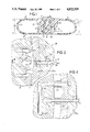
- FIG. 1 is an enlarged fragmentary cross sectional detail view of bag making material embodying the present invention
- FIG. 2 is a enlarged fragmentary plan sectional detail view taken substantially along the line II--II in FIG. 3 and showing apparatus embodying the present invention
- FIG. 3 is a fragmentary vertical sectional detail view taken substantially along the line III--III in FIG. 2;
- FIG. 4 is a fragmentary sectional detail view taken substantially along the line IV--IV in FIG. 3;
- FIG. 5 is a fragmentary sectional elevational detail view of bag making material as extruded in tubular form and before it is collapsed as demonstrated in FIG. 1;
- FIG. 6 is a view similar to FIG. 2, but showing a modification
- FIG. 7 is a fragmentary enlarged cross sectional detail view similar to FIG. 1, but showing the results of extrusion involving the apparatus of FIG. 6.
- extruded bag making material embodying the present invention comprises bag wall film 10 which may conveniently be extruded tubularly as exemplified in FIG. 5 and then collapsed as shown in FIG. 1 for interlocking a reclosable fastener or zipper 11 which includes a male profile 12 and a complementary female profile 13 so located on the inside of the tubular extrusion that when the extrusion is collapsed, the profiles will interlock as shown in FIG. 1.
- the male profile 12 has a stem 14 integral at its base with the film 10 and provided with a generally arrow-shaped head having opposite shoulder lobes 15 and 17 interlockable with respective overhanging shoulders 18 on respective arms 19 of the female profile 13 when the male profile 12 is pressed into a groove 20 in the female profile.
- the female profile is integrally attached to the film 10.
- At least one alignment rib 22 is located integral with the film 10 in spaced parallel adjacent relation to the inner side of the male profile 12 having regard to the eventual bag into which the collapsed extrusion will be converted.
- the shoulder lobe 17 at the inner side of the male profile is larger than the shoulder lobe 15.
- the spacing between the rib 22 and the lobe 17 is sufficient to permit passage of the shoulder bead 18 of the associated arm 19 of the female profile 13 when the profiles are pushed together.
- a second alignment rib 23, substantially like the alignment rib 22, is located integrally on the film 10 in spaced adjacent parallel relation at the opposite or outer side of the profile 12.
- a top end closure fold 24 and a bottom end closure fold 25 appear in the collapsed condition of the bag making extrusion.
- Either of the folds 24 or 25 may be slit longitudinally and spread open as shown in phantom outline for bag filling purposes. Where the bottom fold is slit open, it may be resealed for closing the bag after filling. Similarly, if the bag is to be filled from the top, the top fold may be slit open and after filling the bag the slit ends may be resealed if desired.
- the top fold 24 When the bag is to be opened for discharge of contents, the top fold 24, where it has not been previously slit open, or even where the top end has been resealed, and then slit open, the slit end portions become extensions of bag opening pull flanges 27.
- the alignment ribs 22 and 23 are of a relatively blocky, more or less square, form with generally rounded tip edges, thereby providing improved stiffness in the alignment ribs 22 and 23 for the intended purpose.
- extrusion apparatus 28 comprises a die housing 28a within which is an outer die or sizing ring 29. Within the inner diameter of the ring 29 is an inner die core or ring 30 which cooperates to define a tubular film extrusion orifice 31 to which is fed under pressure, indicated by the arrow 32 in FIG. 3, thermoplastic materials such as polyethylene, or the like extrudate, forced from a supply chamber 33 to the orifice 31.
- Extrudate from the chamber 33 also flows through a male profile flow channel 34 to a profile orifice 35 which connects with the film orifice 31 and by coextrusion joins the base of the just formed male profile 12 to the just formed fresh film 10 just before they issue from the respective orifices.
- a control choke valve 37 arranged to be manipulated from outside the extrusion die assembly which is contained within the housing 28a.
- Formation of the alignment ribs 22 and 23 is desirably effected by coextrusion means cooperatively related to the extrusion means for the film and the male profile.
- an extrudate channel 39 leads from a source under pressure, as represented by the arrow 40 (FIGS. 2 and 3), through and into the housing 28a to a branch channel 41 that extends on through the die ring 29 and a spider 42 bridging the chamber 33 and then joins a header 43 in the inner die member 30. From the header 43 a branch channel 44 leads extrudate to an extrusion orifice 45 for forming the alignment rib 22 in a coextruding relation to the orifice 31 so that the rib 22 and the film 10 are coextruded.
- a rib extrudate channel 47 leads from the header 43 to a coextrusion orifice 48 for the alignment rib 23 at the film orifice 31.
- a choke valve 49 controls the channel 41.
- the tube is expanded or reduced as by air pressure to a desired diameter for producing when collapsed a bag making material of desired width.
- Desirably different tubular diameters may be produced from the same extrusion die.
- the extrusion assembly 28 may, when desired, extrude a tube which when flattened will result in a fifteen inch width so that bags fifteen inches deep will result when the bag making material length is separated into bag sections.
- the film gauge could be about 0.002 inch.
- the same die assembly 28 could be utilized to produce a bag material width of seventeen inches wherein the film gauge could be the same or about 0.004 inch.
- extrudate to the profile forming channel 34 and the rib forming channel 41 is adapted to be controlled concurrently by means of the respective valves 37 and 49 concurrently with the desired extrudate volume to the orifice 31.
- a problem that must be met under all circumstances but especially where different diameters of film tube are to be produced is that of maintaining a proper relation of the alignment ribs 22 and 23 to the male profile 12.
- the ribs 22 and 23 migrate from the associated profile 12. This tendency is accentuated when the film 10 is stretched.
- the shape of the ribs 22 and 23 to distort from the desired cross section.
- a generally flattened stabilizing ridge 50 is formed in the back of the base of the profile 12 in a manner to taper at each side toward the adjacent side of the respective rib 22 or 23.
- the ridge 50 is of a controlled greater thickness behind the profile 12 and then tapers to progressively thinner section toward the adjacent sides of the alignment ribs. This provides a reinforcement beam effect which stabilizes and helps substantially to avoid separating migration of the alignment ribs relative to the associated profile irrespective of the tendency of the ribs to migrate away from the profile, which tendency is accelerated when the diameter of the tubular film is expanded upon extrusion.
- the coextrusion channel 39 leads to and discharges the stabilizing ridge 50 at an orifice 51 which joins the ridge 50 to the freshly extruded film 10 at this orifice.
- Control of the volume of the extrudate in the ridge 50 relative to the volume in the film 10, the profile 12 and the ribs 22 and 23 is effected by means of a choke valve 52 in the downstream end portion of the channel 39 adjacent to the stabilizing ridge orifice 51.
- the extrusion die apparatus 28' and the bag wall film 10' are generally the same as described in connection with the apparatus 28 and the bag wall film 10 in FIGS. 1-5, and it will be understood that similar description applies to all of the elements identified by primed reference numberals in FIGS. 6 and 7 and that various elements and structural relationships involved in the extrusion process and product in FIGS. 1-5 are also applicable to the modification of FIGS. 6 and 7.
- the principal difference in FIGS. 6 and 7 is that in addition to the ridge beam 50' along the base of the fastener profile 12', there is provided a ridge beam 53 along the base of the rib 22' and a ridge beam 54 along the base of the rib 23'.
- the ridge beams 53 and 54 cooperate with the ridge beam 50' in a cooperative rib stabilizing fashion, and the side edges of the ridge beam 50' may, as shown, blend into the ridge beams 53 and 54 in a manner to increase the retention of the ribs 22' and 23' against migrating relative to the profile 12' while nevertheless permiting reasonable hinging action when necessary at junctures 55 along the continguous sides of the ridge beams.
- each of the ridge beams 50', 53 and 54 may be formed by extrudate delivered thereto individually from any desirable source
- the arrangement depicted schematically in FIGS. 6 and 7 shows that a common source delivers extrudate through a channel 39' to manifold chamber 57 from which it is delivered through a branch channel 58 under the control of a choke valve 59 to an orifice 60 for forming the stabilizing ridge beam 50' at the freshly extruded film 10' along the base of the profile 12' being shaped in the extrusion orifice 34'.
- extrudate is delivered from the manifold 57 through a channel 61 under the control of a choke valve 62 to an orifice 63 for forming the stabilizing ridge beam 53 at the film 10' being formed in the film orifice 31' along the base of the rib 22' undergoing formation in the rib extrusion orifice 45'.
- a channel 64 delivers the plastic extrudate from the manifold 57 under the control of a choke valve 65 to a ridge beam forming orifice 67 along the film 10' forming in the orifice 31' along the base of the rib 23' being formed in the rib extrusion orifice 48'.
- the alignment rib sizes respective to film gauge changes can be easily controlled and their migration away from the male profile at least partially prevented.
- independent feed of the extrudate to the alignment ribs permits use of dissimilar extrudate materials either as to density and stiffness which further helps prevent the migration of the ribs from the profile, or to provide extrudate of different colors, or both, whereby to afford various degrees of rigidity and/or colors where desired.
Abstract
Description
Claims (39)
Priority Applications (5)
| Application Number | Priority Date | Filing Date | Title |
|---|---|---|---|
| US07/095,835 US4822539A (en) | 1987-09-14 | 1987-09-14 | Method of and apparatus for extruding bag making material having fastener profiles and alignment ribs, with reinforcing and stabilizing beam effect ridge means |
| GB8815122A GB2209701B (en) | 1987-09-14 | 1988-06-24 | Method of and apparatus for extruding bag-making material having fastener profiles and alignment ribs, and product made thereby |
| FR8811857A FR2620377B1 (en) | 1987-09-14 | 1988-09-12 | COEXTRUSION PROCESS OF A MATERIAL FOR THE MANUFACTURE OF PLASTIC BAGS, DEVICE FOR CARRYING OUT SAID METHOD, AND MATERIAL THEREFOR |
| BE8801048A BE1002953A4 (en) | 1987-09-14 | 1988-09-13 | COEXTRUSION PROCESS OF A MATERIAL FOR THE MANUFACTURE OF PLASTIC BAGS, DEVICE FOR CARRYING OUT SAID METHOD, AND MATERIAL THEREOF. |
| US07/282,694 US4929487A (en) | 1987-09-14 | 1988-12-12 | Bag making material having fastener profiles and alignment ribs with reinforcing and stabilizing beam effect ridge means |
Applications Claiming Priority (1)
| Application Number | Priority Date | Filing Date | Title |
|---|---|---|---|
| US07/095,835 US4822539A (en) | 1987-09-14 | 1987-09-14 | Method of and apparatus for extruding bag making material having fastener profiles and alignment ribs, with reinforcing and stabilizing beam effect ridge means |
Related Child Applications (1)
| Application Number | Title | Priority Date | Filing Date |
|---|---|---|---|
| US07/282,694 Division US4929487A (en) | 1987-09-14 | 1988-12-12 | Bag making material having fastener profiles and alignment ribs with reinforcing and stabilizing beam effect ridge means |
Publications (1)
| Publication Number | Publication Date |
|---|---|
| US4822539A true US4822539A (en) | 1989-04-18 |
Family
ID=22253804
Family Applications (1)
| Application Number | Title | Priority Date | Filing Date |
|---|---|---|---|
| US07/095,835 Expired - Fee Related US4822539A (en) | 1987-09-14 | 1987-09-14 | Method of and apparatus for extruding bag making material having fastener profiles and alignment ribs, with reinforcing and stabilizing beam effect ridge means |
Country Status (4)
| Country | Link |
|---|---|
| US (1) | US4822539A (en) |
| BE (1) | BE1002953A4 (en) |
| FR (1) | FR2620377B1 (en) |
| GB (1) | GB2209701B (en) |
Cited By (36)
| Publication number | Priority date | Publication date | Assignee | Title |
|---|---|---|---|---|
| US4985192A (en) * | 1988-04-21 | 1991-01-15 | Roeder Industrial Holdings Limited | Methods and apparatus for producing fastener profiles, and products incorporating the same |
| US5141577A (en) * | 1990-05-18 | 1992-08-25 | Dowbrands L.P. | Closure for reclosable thermoplastic containers |
| US5411692A (en) * | 1994-04-11 | 1995-05-02 | Reynolds Consumer Products Inc. | Integral reclosable bag die assembly |
| US5425911A (en) * | 1991-08-27 | 1995-06-20 | Reynolds Consumer Products Inc. | Method for manufacture of integral reclosable bag |
| EP0666041A1 (en) * | 1994-01-11 | 1995-08-09 | Illinois Tool Works Inc. | Profiled interlocking closure strap with wedge-shaped parts |
| US5558613A (en) * | 1993-12-28 | 1996-09-24 | Minigrap, Inc. | Method for reducing the variance in the forces needed to open reclosable plastic bags from within and from without |
| EP0940097A2 (en) * | 1998-03-06 | 1999-09-08 | Illinois Tool Works Inc. | Zipper strip and reclosable package |
| US6033113A (en) * | 1998-08-18 | 2000-03-07 | Cti Industries Corporation | Seal for zipper-type plastic bags and the like |
| US6439771B1 (en) | 2000-03-15 | 2002-08-27 | Webster Industries Division Chelsea Industries, Inc. | Zippered resealable closure |
| EP1334038A1 (en) * | 2000-10-27 | 2003-08-13 | International Consolidated Business Pty Ltd. | Reclosable plastic bags |
| US20040000743A1 (en) * | 2002-06-27 | 2004-01-01 | Pawloski James C. | Method and apparatus for forming a guide rib on a section of plastic film |
| US20040001651A1 (en) * | 2002-06-27 | 2004-01-01 | Pawloski James C. | Closure device for a reclosable pouch |
| US20040047521A1 (en) * | 2002-09-05 | 2004-03-11 | Edward Berich | Ease of closure through tactile/optical means |
| US20040057775A1 (en) * | 2000-10-10 | 2004-03-25 | Golding-Griessel Lester Harold | Coupling device |
| US20040078939A1 (en) * | 2002-10-23 | 2004-04-29 | Pawloski James C. | Closure device for a reclosable pouch |
| US20040234171A1 (en) * | 2003-05-19 | 2004-11-25 | Dais Brian C. | Reclosable pouch with closure device that allows venting and/or an air-tight seal |
| US20040234170A1 (en) * | 2003-05-19 | 2004-11-25 | Pawloski James C | Closure device for a reclosable pouch |
| US20050060849A1 (en) * | 2003-09-18 | 2005-03-24 | Vanbenschoten Brian J. | Coextruded hook fasteners |
| US20050263361A1 (en) * | 2004-05-28 | 2005-12-01 | Achim Schulz | Spring-damper-system for a motor vehicle carriage |
| US20050271307A1 (en) * | 2004-06-04 | 2005-12-08 | Pawloski James C | Closure device for a reclosable pouch |
| US20050271308A1 (en) * | 2004-06-04 | 2005-12-08 | Pawloski James C | Closure device for a reclosable pouch |
| AU2001273731B2 (en) * | 2000-10-27 | 2006-09-14 | Intellectual Property Development Corporation Pty Ltd | Reclosable plastic bags |
| US7494333B2 (en) | 2004-06-04 | 2009-02-24 | S.C. Johnson Home Storage, Inc. | Apparatus for forming multiple closure elements |
| US20090154843A1 (en) * | 2005-10-31 | 2009-06-18 | Reynolds Consumer Products, Inc. | Polymeric package closure and method |
| US7674040B2 (en) | 2006-12-29 | 2010-03-09 | Illinois Tool Works Inc. | Reclosable bag having double closure |
| US20100303390A1 (en) * | 2009-05-29 | 2010-12-02 | Ackerman Bryan L | Closure mechanism and method of closing |
| US20110083799A1 (en) * | 2009-10-08 | 2011-04-14 | Illinois Tool Works Inc. | Tie layer between a polylactic acid film and a polyethylene zipper or other component |
| US20110165280A1 (en) * | 2008-07-15 | 2011-07-07 | Illinois Tool Work Inc. | Method to accurately control size, velocity, and relative position sets of reclosable mechanism |
| US8469592B2 (en) | 2010-06-22 | 2013-06-25 | S.C. Johnson & Son, Inc. | Tactile enhancement mechanism for a closure mechanism |
| US8469593B2 (en) | 2011-02-22 | 2013-06-25 | S.C. Johnson & Son, Inc. | Reclosable bag having a press-to-vent zipper |
| US8550716B2 (en) | 2010-06-22 | 2013-10-08 | S.C. Johnson & Son, Inc. | Tactile enhancement mechanism for a closure mechanism |
| US8568031B2 (en) | 2011-02-22 | 2013-10-29 | S.C. Johnson & Son, Inc. | Clicking closure device for a reclosable pouch |
| US8926179B2 (en) | 2010-07-27 | 2015-01-06 | S.C. Johnson & Son, Inc. | Closure mechanism with multiple frequency feedback |
| US8974118B2 (en) | 2010-10-29 | 2015-03-10 | S.C. Johnson & Son, Inc. | Reclosable bag having a sound producing zipper |
| US9327875B2 (en) | 2010-10-29 | 2016-05-03 | S.C. Johnson & Son, Inc. | Reclosable bag having a loud sound during closing |
| US11180286B2 (en) | 2010-10-29 | 2021-11-23 | S. C. Johnson & Son, Inc. | Reclosable bag having a loud sound during closing |
Families Citing this family (2)
| Publication number | Priority date | Publication date | Assignee | Title |
|---|---|---|---|---|
| US5087488A (en) * | 1989-10-19 | 1992-02-11 | Aeroquip Corporation | Method and apparatus for forming a plastic article with an overlay of varying thickness having a shaded color appearance |
| DE3937088A1 (en) * | 1989-11-07 | 1991-05-08 | Asf Verwaltungsgesellschaft Mb | CLOSURE FOR SEALING BAGS AND METHOD AND TOOL FOR THE PRODUCTION THEREOF |
Citations (15)
| Publication number | Priority date | Publication date | Assignee | Title |
|---|---|---|---|---|
| US27174A (en) * | 1860-02-14 | Improvement in cultivators | ||
| US3198228A (en) * | 1961-11-27 | 1965-08-03 | Seisan Nipponsha Kk | Integral reclosable bag |
| US3543343A (en) * | 1967-05-03 | 1970-12-01 | Minigrip Inc | Tube extruder |
| US3565737A (en) * | 1965-11-26 | 1971-02-23 | Dow Chemical Co | Composite plastic sheet and method for the preparation thereof |
| US3715420A (en) * | 1969-07-19 | 1973-02-06 | Sekisui Chemical Co Ltd | Process for producing a thermoplastic resin sheet having a color band |
| US3841816A (en) * | 1971-06-30 | 1974-10-15 | Minigrip Inc | Apparatus for extruding tubing for fastener bags |
| GB1444326A (en) * | 1974-05-16 | 1976-07-28 | Minigrip London Ltd | Apparatus for making sheets with interengageable closure elements |
| US4125585A (en) * | 1976-12-17 | 1978-11-14 | Hpm Corporation | Process employing coextrusion feedblock |
| GB2046660A (en) * | 1979-03-30 | 1980-11-19 | Union Carbide Corp | Apparatus and Method for Producing a Plastics Closure Strip |
| US4263079A (en) * | 1978-12-15 | 1981-04-21 | The Dow Chemical Company | Method of forming an integral closure for a thermoplastic container |
| EP0114373A2 (en) * | 1982-12-27 | 1984-08-01 | The Dow Chemical Company | Improved closure and method for producing thermoplastic containers |
| US4562027A (en) * | 1984-03-21 | 1985-12-31 | The Dow Chemical Company | Process for making cast thermoplastic film with integral closures |
| US4563319A (en) * | 1983-03-03 | 1986-01-07 | Minigrip, Inc. | Method of making quadruple profile tubing |
| US4672723A (en) * | 1985-11-04 | 1987-06-16 | Minigrip, Inc. | Stabilized reclosable extruded plastic fasteners |
| US4741789A (en) * | 1986-10-20 | 1988-05-03 | The Dow Chemical Company | Apparatus and process for forming and applying a profile and adjacent rib-type zipper to a traveling film web |
Family Cites Families (5)
| Publication number | Priority date | Publication date | Assignee | Title |
|---|---|---|---|---|
| DE1779949C3 (en) * | 1965-08-27 | 1974-12-19 | Etimex Kunststoffwerke Gmbh, 7000 Stuttgart | Method and extrusion tool for producing an open or tubular plastic web. Eliminated from: 1479151 |
| USRE27174E (en) * | 1970-01-23 | 1971-09-21 | Reclosable bags with rib and groove elements | |
| EP0063189B1 (en) * | 1981-04-16 | 1985-06-19 | The Dow Chemical Company | Method and apparatus for forming an integral closure for a thermoplastic container |
| JPS60125651A (en) * | 1983-12-02 | 1985-07-04 | Seisan Nipponsha Kk | Molding and bonding of plastic fastener and plastic affix onto film |
| US4665557A (en) * | 1986-07-22 | 1987-05-12 | First Brands Corporation | Multiple omega closures |
-
1987
- 1987-09-14 US US07/095,835 patent/US4822539A/en not_active Expired - Fee Related
-
1988
- 1988-06-24 GB GB8815122A patent/GB2209701B/en not_active Expired - Lifetime
- 1988-09-12 FR FR8811857A patent/FR2620377B1/en not_active Expired - Fee Related
- 1988-09-13 BE BE8801048A patent/BE1002953A4/en not_active IP Right Cessation
Patent Citations (15)
| Publication number | Priority date | Publication date | Assignee | Title |
|---|---|---|---|---|
| US27174A (en) * | 1860-02-14 | Improvement in cultivators | ||
| US3198228A (en) * | 1961-11-27 | 1965-08-03 | Seisan Nipponsha Kk | Integral reclosable bag |
| US3565737A (en) * | 1965-11-26 | 1971-02-23 | Dow Chemical Co | Composite plastic sheet and method for the preparation thereof |
| US3543343A (en) * | 1967-05-03 | 1970-12-01 | Minigrip Inc | Tube extruder |
| US3715420A (en) * | 1969-07-19 | 1973-02-06 | Sekisui Chemical Co Ltd | Process for producing a thermoplastic resin sheet having a color band |
| US3841816A (en) * | 1971-06-30 | 1974-10-15 | Minigrip Inc | Apparatus for extruding tubing for fastener bags |
| GB1444326A (en) * | 1974-05-16 | 1976-07-28 | Minigrip London Ltd | Apparatus for making sheets with interengageable closure elements |
| US4125585A (en) * | 1976-12-17 | 1978-11-14 | Hpm Corporation | Process employing coextrusion feedblock |
| US4263079A (en) * | 1978-12-15 | 1981-04-21 | The Dow Chemical Company | Method of forming an integral closure for a thermoplastic container |
| GB2046660A (en) * | 1979-03-30 | 1980-11-19 | Union Carbide Corp | Apparatus and Method for Producing a Plastics Closure Strip |
| EP0114373A2 (en) * | 1982-12-27 | 1984-08-01 | The Dow Chemical Company | Improved closure and method for producing thermoplastic containers |
| US4563319A (en) * | 1983-03-03 | 1986-01-07 | Minigrip, Inc. | Method of making quadruple profile tubing |
| US4562027A (en) * | 1984-03-21 | 1985-12-31 | The Dow Chemical Company | Process for making cast thermoplastic film with integral closures |
| US4672723A (en) * | 1985-11-04 | 1987-06-16 | Minigrip, Inc. | Stabilized reclosable extruded plastic fasteners |
| US4741789A (en) * | 1986-10-20 | 1988-05-03 | The Dow Chemical Company | Apparatus and process for forming and applying a profile and adjacent rib-type zipper to a traveling film web |
Cited By (64)
| Publication number | Priority date | Publication date | Assignee | Title |
|---|---|---|---|---|
| US4985192A (en) * | 1988-04-21 | 1991-01-15 | Roeder Industrial Holdings Limited | Methods and apparatus for producing fastener profiles, and products incorporating the same |
| US5141577A (en) * | 1990-05-18 | 1992-08-25 | Dowbrands L.P. | Closure for reclosable thermoplastic containers |
| US5425911A (en) * | 1991-08-27 | 1995-06-20 | Reynolds Consumer Products Inc. | Method for manufacture of integral reclosable bag |
| US5558613A (en) * | 1993-12-28 | 1996-09-24 | Minigrap, Inc. | Method for reducing the variance in the forces needed to open reclosable plastic bags from within and from without |
| EP0666041A1 (en) * | 1994-01-11 | 1995-08-09 | Illinois Tool Works Inc. | Profiled interlocking closure strap with wedge-shaped parts |
| US5411692A (en) * | 1994-04-11 | 1995-05-02 | Reynolds Consumer Products Inc. | Integral reclosable bag die assembly |
| EP0940097A3 (en) * | 1998-03-06 | 2000-03-29 | Illinois Tool Works Inc. | Zipper strip and reclosable package |
| EP0940097A2 (en) * | 1998-03-06 | 1999-09-08 | Illinois Tool Works Inc. | Zipper strip and reclosable package |
| US6033113A (en) * | 1998-08-18 | 2000-03-07 | Cti Industries Corporation | Seal for zipper-type plastic bags and the like |
| US6439771B1 (en) | 2000-03-15 | 2002-08-27 | Webster Industries Division Chelsea Industries, Inc. | Zippered resealable closure |
| US20040057775A1 (en) * | 2000-10-10 | 2004-03-25 | Golding-Griessel Lester Harold | Coupling device |
| EP1334038A4 (en) * | 2000-10-27 | 2005-02-16 | Int Cons Business Pty Ltd | Reclosable plastic bags |
| EP1334038A1 (en) * | 2000-10-27 | 2003-08-13 | International Consolidated Business Pty Ltd. | Reclosable plastic bags |
| US20040013323A1 (en) * | 2000-10-27 | 2004-01-22 | Withers Philip Craig | Reclosable plastic bags |
| AU2001273731B2 (en) * | 2000-10-27 | 2006-09-14 | Intellectual Property Development Corporation Pty Ltd | Reclosable plastic bags |
| US7651271B2 (en) | 2000-10-27 | 2010-01-26 | International Consolidated Business Pty Ltd. | Reclosable plastic bags |
| US20040000743A1 (en) * | 2002-06-27 | 2004-01-01 | Pawloski James C. | Method and apparatus for forming a guide rib on a section of plastic film |
| US20040001651A1 (en) * | 2002-06-27 | 2004-01-01 | Pawloski James C. | Closure device for a reclosable pouch |
| US6994535B2 (en) | 2002-06-27 | 2006-02-07 | S.C. Johnson Home Storage, Inc. | Method and apparatus for forming a guide rib on a section of plastic film |
| US20040047521A1 (en) * | 2002-09-05 | 2004-03-11 | Edward Berich | Ease of closure through tactile/optical means |
| US6877898B2 (en) | 2002-09-05 | 2005-04-12 | Illinois Tool Works Inc. | Ease of closure through tactile/optical means |
| US20040078938A1 (en) * | 2002-10-23 | 2004-04-29 | Pawloski James C. | Closure device for a reclosable pouch |
| US20040078939A1 (en) * | 2002-10-23 | 2004-04-29 | Pawloski James C. | Closure device for a reclosable pouch |
| US20040234170A1 (en) * | 2003-05-19 | 2004-11-25 | Pawloski James C | Closure device for a reclosable pouch |
| US20040234171A1 (en) * | 2003-05-19 | 2004-11-25 | Dais Brian C. | Reclosable pouch with closure device that allows venting and/or an air-tight seal |
| US7410298B2 (en) | 2003-05-19 | 2008-08-12 | S.C. Johnson Home Storage, Inc. | Closure device for a reclosable pouch |
| US7137736B2 (en) | 2003-05-19 | 2006-11-21 | S.C. Johnson Home Storage, Inc. | Closure device for a reclosable pouch |
| US20050060849A1 (en) * | 2003-09-18 | 2005-03-24 | Vanbenschoten Brian J. | Coextruded hook fasteners |
| US7172008B2 (en) | 2003-09-18 | 2007-02-06 | Velcro Industries B.V. | Hook fasteners and methods of making the same |
| US20070134465A1 (en) * | 2003-09-18 | 2007-06-14 | Velcro Industries, B.V., A Netherlands Corporation | Hook fasteners and methods of making the same |
| US20050263361A1 (en) * | 2004-05-28 | 2005-12-01 | Achim Schulz | Spring-damper-system for a motor vehicle carriage |
| US7494333B2 (en) | 2004-06-04 | 2009-02-24 | S.C. Johnson Home Storage, Inc. | Apparatus for forming multiple closure elements |
| US7850368B2 (en) | 2004-06-04 | 2010-12-14 | S.C. Johnson & Son, Inc. | Closure device for a reclosable pouch |
| US20050271307A1 (en) * | 2004-06-04 | 2005-12-08 | Pawloski James C | Closure device for a reclosable pouch |
| US20050271308A1 (en) * | 2004-06-04 | 2005-12-08 | Pawloski James C | Closure device for a reclosable pouch |
| US20090154843A1 (en) * | 2005-10-31 | 2009-06-18 | Reynolds Consumer Products, Inc. | Polymeric package closure and method |
| US7743474B2 (en) | 2005-10-31 | 2010-06-29 | Reynolds Consumer Products, Inc. | Polymeric package closure and method |
| US7674040B2 (en) | 2006-12-29 | 2010-03-09 | Illinois Tool Works Inc. | Reclosable bag having double closure |
| US20110165280A1 (en) * | 2008-07-15 | 2011-07-07 | Illinois Tool Work Inc. | Method to accurately control size, velocity, and relative position sets of reclosable mechanism |
| US9139340B2 (en) | 2009-05-29 | 2015-09-22 | S.C. Johnson & Son, Inc. | Reclosable pouch with an elongate closure mechanism and a method of closing such a pouch |
| US11299326B2 (en) | 2009-05-29 | 2022-04-12 | S. C. Johnson & Son, Inc. | Reclosable pouch with an elongate closure mechanism |
| US10974871B2 (en) | 2009-05-29 | 2021-04-13 | S. C. Johnson & Son, Inc. | Reclosable pouch with an elongate closure mechanism |
| US8578572B2 (en) * | 2009-05-29 | 2013-11-12 | S.C. Johnson & Son, Inc. | Closure mechanism and method of closing |
| US10266308B2 (en) | 2009-05-29 | 2019-04-23 | S. C. Johnson & Son, Inc. | Reclosable pouch with an elongate closure mechanism |
| US20100303390A1 (en) * | 2009-05-29 | 2010-12-02 | Ackerman Bryan L | Closure mechanism and method of closing |
| US9738422B2 (en) | 2009-05-29 | 2017-08-22 | S. C. Johnson & Son, Inc. | Reclosable pouch with an elongate closure mechanism |
| US20110083799A1 (en) * | 2009-10-08 | 2011-04-14 | Illinois Tool Works Inc. | Tie layer between a polylactic acid film and a polyethylene zipper or other component |
| US8469592B2 (en) | 2010-06-22 | 2013-06-25 | S.C. Johnson & Son, Inc. | Tactile enhancement mechanism for a closure mechanism |
| US8550716B2 (en) | 2010-06-22 | 2013-10-08 | S.C. Johnson & Son, Inc. | Tactile enhancement mechanism for a closure mechanism |
| US10077140B2 (en) | 2010-07-27 | 2018-09-18 | S. C. Johnson & Son, Inc. | Closure mechanism with multiple frequency feedback |
| US10518937B2 (en) | 2010-07-27 | 2019-12-31 | S.C. Johnson & Son, Inc. | Closure mechanism with multiple frequency feedback |
| US9434514B2 (en) | 2010-07-27 | 2016-09-06 | S. C. Johnson & Son, Inc. | Closure mechanism with multiple frequency feedback |
| US8926179B2 (en) | 2010-07-27 | 2015-01-06 | S.C. Johnson & Son, Inc. | Closure mechanism with multiple frequency feedback |
| US11691789B2 (en) | 2010-10-29 | 2023-07-04 | S. C. Johnson & Son, Inc. | Reclosable bag having a loud sound during closing |
| US9327875B2 (en) | 2010-10-29 | 2016-05-03 | S.C. Johnson & Son, Inc. | Reclosable bag having a loud sound during closing |
| US9914563B2 (en) | 2010-10-29 | 2018-03-13 | S. C. Johnson & Son, Inc. | Reclosable bag having a loud sound during closing |
| US11180286B2 (en) | 2010-10-29 | 2021-11-23 | S. C. Johnson & Son, Inc. | Reclosable bag having a loud sound during closing |
| US8974118B2 (en) | 2010-10-29 | 2015-03-10 | S.C. Johnson & Son, Inc. | Reclosable bag having a sound producing zipper |
| US9126735B2 (en) | 2011-02-22 | 2015-09-08 | S.C. Johnson & Son, Inc. | Reclosable pouch having a clicking closure device |
| US10618697B2 (en) | 2011-02-22 | 2020-04-14 | S. C. Johnson & Son, Inc. | Reclosable pouch having a clicking closure device |
| US8568031B2 (en) | 2011-02-22 | 2013-10-29 | S.C. Johnson & Son, Inc. | Clicking closure device for a reclosable pouch |
| US10011396B2 (en) | 2011-02-22 | 2018-07-03 | S. C. Johnson & Son, Inc. | Reclosable pouch having a clicking closure device |
| US8469593B2 (en) | 2011-02-22 | 2013-06-25 | S.C. Johnson & Son, Inc. | Reclosable bag having a press-to-vent zipper |
| US9475616B2 (en) | 2011-02-22 | 2016-10-25 | S.C. Johnson & Son, Inc. | Reclosable pouch having a clicking closure device |
Also Published As
| Publication number | Publication date |
|---|---|
| FR2620377A1 (en) | 1989-03-17 |
| GB8815122D0 (en) | 1988-08-03 |
| GB2209701B (en) | 1991-09-18 |
| FR2620377B1 (en) | 1993-12-17 |
| GB2209701A (en) | 1989-05-24 |
| BE1002953A4 (en) | 1991-10-01 |
Similar Documents
| Publication | Publication Date | Title |
|---|---|---|
| US4822539A (en) | Method of and apparatus for extruding bag making material having fastener profiles and alignment ribs, with reinforcing and stabilizing beam effect ridge means | |
| US4929487A (en) | Bag making material having fastener profiles and alignment ribs with reinforcing and stabilizing beam effect ridge means | |
| US4235653A (en) | Method for making reclosable bags | |
| US4285376A (en) | Reclosable plastic bag construction made from a one piece extrusion | |
| US3535409A (en) | Method of making sheet material with film tear line | |
| US4840611A (en) | Gusseted bags with reclosure features | |
| US4430070A (en) | Method of and apparatus for uninterruptedly assembling components for making bags | |
| US4736450A (en) | Gusseted bags with reclosure features | |
| US3368740A (en) | Sheet material with film tear line | |
| US3532571A (en) | Method and apparatus for forming continuous plastic tubing with separable pressure reclosable fastener strips attached to the surface thereof | |
| US5425216A (en) | Method of making reclosable plastic bags on a form, fill and seal machine with open zipper profiles | |
| US5551208A (en) | Method for applying zipper to film at tube on a form-fill-and-seal | |
| US4683015A (en) | Method of forming flexible fastener elements and securing them to a traveling web | |
| US3543343A (en) | Tube extruder | |
| US4249982A (en) | Apparatus for making reclosable bags | |
| US4657792A (en) | Funnel material for bags and method | |
| US3362302A (en) | Bag closure | |
| EP0200921B1 (en) | Extruded plastic material for making three recloseable bag sections | |
| US4764977A (en) | Reclosable plastic container | |
| US20070094850A1 (en) | Reclosable container and method of manufacture | |
| DE3335551A1 (en) | METHOD FOR PRODUCING PARTLY SEPARATE MULTIPLE BAGS | |
| US3389733A (en) | Flexible container of plastic material | |
| GB1399744A (en) | Method and apparatus for making sheets and tubes for forming into bags | |
| US3202559A (en) | Method of forming plastic bags with slide fastener tape assemblies welded thereto | |
| US3051605A (en) | Method of making valved bags from extruded thermoplastic materials |
Legal Events
| Date | Code | Title | Description |
|---|---|---|---|
| AS | Assignment |
Owner name: MINIGRIP, INC., ROUTE 303, ORANGEBURG, NEW YORK A Free format text: ASSIGNMENT OF ASSIGNORS INTEREST.;ASSIGNORS:TILMAN, PAUL A.;MACHACEK, ZDENEK;SCOTT, RICHMOND;REEL/FRAME:004768/0124 Effective date: 19870831 Owner name: MINIGRIP, INC., A CORP. OF DE.,NEW YORK Free format text: ASSIGNMENT OF ASSIGNORS INTEREST;ASSIGNORS:TILMAN, PAUL A.;MACHACEK, ZDENEK;SCOTT, RICHMOND;REEL/FRAME:004768/0124 Effective date: 19870831 |
|
| FEPP | Fee payment procedure |
Free format text: PAYOR NUMBER ASSIGNED (ORIGINAL EVENT CODE: ASPN); ENTITY STATUS OF PATENT OWNER: LARGE ENTITY |
|
| FPAY | Fee payment |
Year of fee payment: 4 |
|
| REMI | Maintenance fee reminder mailed | ||
| LAPS | Lapse for failure to pay maintenance fees | ||
| FP | Lapsed due to failure to pay maintenance fee |
Effective date: 19970423 |
|
| STCH | Information on status: patent discontinuation |
Free format text: PATENT EXPIRED DUE TO NONPAYMENT OF MAINTENANCE FEES UNDER 37 CFR 1.362 |