US4826136A - Lumber turning tool with leverage enhancing claw surfaces - Google Patents
Lumber turning tool with leverage enhancing claw surfaces Download PDFInfo
- Publication number
- US4826136A US4826136A US07/147,507 US14750788A US4826136A US 4826136 A US4826136 A US 4826136A US 14750788 A US14750788 A US 14750788A US 4826136 A US4826136 A US 4826136A
- Authority
- US
- United States
- Prior art keywords
- claw
- claws
- combination
- space
- tines
- Prior art date
- Legal status (The legal status is an assumption and is not a legal conclusion. Google has not performed a legal analysis and makes no representation as to the accuracy of the status listed.)
- Expired - Lifetime
Links
Images


Classifications
-
- B—PERFORMING OPERATIONS; TRANSPORTING
- B25—HAND TOOLS; PORTABLE POWER-DRIVEN TOOLS; MANIPULATORS
- B25C—HAND-HELD NAILING OR STAPLING TOOLS; MANUALLY OPERATED PORTABLE STAPLING TOOLS
- B25C11/00—Nail, spike, and staple extractors
-
- B—PERFORMING OPERATIONS; TRANSPORTING
- B25—HAND TOOLS; PORTABLE POWER-DRIVEN TOOLS; MANIPULATORS
- B25F—COMBINATION OR MULTI-PURPOSE TOOLS NOT OTHERWISE PROVIDED FOR; DETAILS OR COMPONENTS OF PORTABLE POWER-DRIVEN TOOLS NOT PARTICULARLY RELATED TO THE OPERATIONS PERFORMED AND NOT OTHERWISE PROVIDED FOR
- B25F1/00—Combination or multi-purpose hand tools
Definitions
- This invention relates generally to tools of the type used for prying or loosening; and more particularly concerns a tool constructed especially to fit heavy duty lumber pieces, for prying them or forcibly twisting them, into desired positions, as for release from attachment to other members or for positioning them for nailing.
- the tool comprises:
- one of the claws at one side of said space being substantially shorter in length than the other of the claws at the opposite side of said space, each of said claws being bifurcated to define tines, at opposite sides of a slot,
- said integral head including a transverse section interconnecting the claws, said claws having first inner surfaces defining faces that are parallel throughout their lengths at opposite sides of said space, said space having an innermost side, said transverse section having a transverse face at said innermost side of said space, said transverse face always extending in a plane that is normal to planes defined by said parallel faces,
- said one claw having an outwardly convex outer surface to engage a work surface, and a second inner surface offset relative to said first inner surface thereof and toward said convex outer surface, said tines of the one claw having opposed faces that merge together at a locus that intersects said second inner surface.
- the head is typically C-shaped; a lumber member is receivable in the space between the claws to engage the transverse face of the transverse section; and said transverse face extends in a plane that is normal to planes defined by said parallel inner faces of the claws.
- the claws have outer surfaces and the inner and outer surfaces of each claw taper toward a tip; and the tips are located at substantially different distances from the transverse inner face of the head.
- each claw is typically bifurcated to define tines having edges for nail gripping; and the tine edges of one claw are typically straight, whereas the tine edges of the other claw are typically concave, whereby nails of a wide range of cross-section sizes may be gripped and pulled. Further, the tines taper toward tips, facilitating penetration of the claws beneath members to be pried loose from connection to other members. Also, the second and offset inner surface of the one claw provides for greater leverage exertion on a nail head engaging that surface.
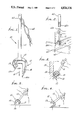
- FIG. 1 is an elevation in perspective showing a tool embodying the invention
- FIGS. 2-5 are perspective showing various uses of the FIG. 1 tool
- FIG. 6 is a fragmentary side view of the head of the FIG. 1 tool
- FIG. 7 is a top plan view taken on lines 7--7 of FIG. 6;
- FIG. 8 is a bottom plan view taken on lines 8--8 of FIG. 6;
- FIG. 9 is a section taken on lines 9--9 of FIG. 7;
- FIG. 10 is a section taken on lines 10--10 of FIG. 9;
- FIG. 11 is a sec-ion taken on lines 11--11 of FIG. 6;
- FIG. 12 is a side elevation showing a modified tool
- FIGS. 13 and 14 are views taken on lines 13--13 and 14--14 of FIG. 12, respectively;
- FIG. 15 is a side view on lines 15--15 of FIG. 14;
- FIGS. 16 and 17 are views like FIG. 15, but showing stages in leverage exertion during nail pulling.
- the lever type tool 10 comprises an elongated handle 11, and a head 12 integral with the handle at one end thereof. Both the head and handle may consist of steel, the head being hardened. It has two spaced apart claws 13 and 14 projecting in generally the same direction, see arrow 15, and at opposite sides of a space 16, to closely receive a portion 17a of a rectangular cross section 17 of a lumber member, as for example a wooden two inch by four inch section as is commonly used in construction framing.
- One of the claws, i.e. claw 13, as shown is substantially shorter in length than the other, claw 14 as shown, for several reasons as will appear. One reason is to facilitate grasping of the member 17, as shown in FIG. 2, with full reception of the lumber portion 17a into space 16.
- Head 12 is C-shaped, and the claws taper toward their tips at 13a and 14a. This facilitates loosening, as by prying, of a member 17 nailed at 18 to another member or wall 19.
- Elongated claw 14 progressively penetrates behind the member 17, i.e. between member 17 and wall 19 during such prying, and during progressive grasping of the portion 17a by the claws.
- the head also includes a transverse section 20 interconnecting the claws, section 2- having a transverse face 20a at the innermost side of space 16.
- Face 2a extends in a plane that is normal to planes defined by parallel faces 13b and 14b of the claws, at opposite sides of space 16.
- Face 20a squarely and closely faces (and may engage) the end 17b of a wooden member 17 when faces 13b and 14b engage opposite sides 17c and 17d of that member, as is clear from FIGS. 2 and 6.
- the length d l between face 20a and tip 14a is approximately 2.5. times the length d 2 between face 20a and tip 13a.
- d l is about 7.5 centimeters
- d 2 is about 3 centimeters in length.
- outer surfaces 13e and 14e of the claws are outwardly convex, along these lengths between the transverse member 20 (with which such outer surfaces merge) and the tips 13a and 14a, for maximum claw strength, and also to permit rocking against the surface of a member as at 19 in FIG. 3.
- each rod claw is typically bifurcated, so as to form tines 13f and 13g associated with claw 13, and tines 14f and 14g associated with claw 14.
- the split 22 between tines 13f and 13g tapers toward an inner terminus 22a; and the split 23 between tines 14f and 14g tapers toward an inner terminus 23a. See FIGS. 7-11 in these regards.
- the jaw edges 22b and 22c defined by split 22 may be concavely curved (as viewed in FIGS. 7 and 11) toward terminus 22a, whereby a nail 24 of relatively larger cross section may be grasped by such edges for ease of nail pulling (see FIG. 5); whereas the jaw edges 23b and 23c defined by split 23 (see FIG. 8) are linear, whereby a nail 25 of relatively lesser cross section may be grasped by such edges for ease of nail pulling (see FIG. 4). Note the large amount of leverage permitted, as in FIG. 5.
- the inner sides of the tines of each claw are recessed, to define bowl shaped depressions as at 30 and 31.
- Such recesses are adapted to receive nail heads during nail pulling, whereby the extent of the tine penetration required under or behind a nail head is minimized.
- the opposite sides of the head 12 may be recessed as at 35-37, to reduce head weight.
- FIG. 2 illustrates an important use of the tool 10. It is shown gripping an elongated wooden member 17 of rectangular cross section, for twisting its end 60a into position for nailing connection to a transverse wooden 61.
- One nail 62 extending through member 61 and into end 60a acts as a pivot, and the tool forcibly rotates the end 60a into position to receive a second nail through member 61 into end 60a securing it in position.
- the opposite remote end of member 17 is rigidly secured to other structure.
- Increased torque can be applied by connection of a bar 65 to the handle, as seen in FIG. 2.
- Bar 65 has a tubular end 65a adapted to closely fit over the end 11a of the tool handle, as shown. Note opening 70, for a tool hanging peg.
- FIG. 1 also shows a thong 68 attached at 69 to the handle, for ease of supporting the tool when not in use.
- the one claw 112 (corresponding to claw 12) has a first inner surface 113 bifurcated by split or slot 114 to define inner surface portions 113a and 113b which are substantially rectangular, as seen in FIG. 14. Opposite sides 114a and 114b of the slot are parallel. That claw also has a second inner surface 116 that is offset relative to surface 113, and outwardly toward the outwardly convex outer surface 117 of that claw. Surface 117 engages the work surface 118 during pulling of a nail, as seen in FIGS. 16 and 17.
- the opposed parallel sides 114a and 114b of the slot merge together at a locus 119 that intersects the second inner surface at 119a. That locus positions the shank 120a of a nail 120 received in a position wherein the nail head 120b engages the second surface, as in FIG. 17.
- the nail head is then located against offset surface 116 to provide substantially enhanced leverage exertion upon a nail, with curved outer surface 117 engaging the work.
- claw surface 113 initially lifts the nail head as shown, with leverage exerted between plane 123 intersecting the work at the point surface 117 engages it, and plane 124 passing through the nail head. After the nail is lifted somewhat, the claw is pushed further under the nail head, to the position of FIG. 17, wherein the head now engages offset surface 116 as the claw is rocked. This enables greater leverage exertion between planes 123a and 124a corresponding to planes 123 and 124, but closer together.
- Surfaces 113 and 116 are parallel. Slot 114 intersects surface 113 along its entire length, but intersects only part of the length of surface 116.
Abstract
Description
d.sub.1 =7.5 cm.
d.sub.2 =3 cm.
d.sub.3 =9.4 cm.
d.sub.4 =4.3 cm.
d.sub.5 -2.5. cm.
d.sub.6 =3 cm.
Claims (14)
Priority Applications (4)
| Application Number | Priority Date | Filing Date | Title |
|---|---|---|---|
| US07/147,507 US4826136A (en) | 1987-01-12 | 1988-01-25 | Lumber turning tool with leverage enhancing claw surfaces |
| PCT/US1989/000281 WO1989006635A1 (en) | 1988-01-25 | 1989-01-23 | Lumber turning tool with leverage enhancing claw surfaces |
| AU30560/89A AU3056089A (en) | 1988-01-25 | 1989-01-23 | Lumber turning tool with leverage enhancing claw surfaces |
| CA000588952A CA1291473C (en) | 1988-01-25 | 1989-01-24 | Lumber turning tool with leverage enhancing claw surfaces |
Applications Claiming Priority (2)
| Application Number | Priority Date | Filing Date | Title |
|---|---|---|---|
| US07/002,748 US4762303A (en) | 1987-01-12 | 1987-01-12 | Lumber turning tool |
| US07/147,507 US4826136A (en) | 1987-01-12 | 1988-01-25 | Lumber turning tool with leverage enhancing claw surfaces |
Related Parent Applications (1)
| Application Number | Title | Priority Date | Filing Date |
|---|---|---|---|
| US07/002,748 Continuation-In-Part US4762303A (en) | 1987-01-12 | 1987-01-12 | Lumber turning tool |
Publications (1)
| Publication Number | Publication Date |
|---|---|
| US4826136A true US4826136A (en) | 1989-05-02 |
Family
ID=22521841
Family Applications (1)
| Application Number | Title | Priority Date | Filing Date |
|---|---|---|---|
| US07/147,507 Expired - Lifetime US4826136A (en) | 1987-01-12 | 1988-01-25 | Lumber turning tool with leverage enhancing claw surfaces |
Country Status (4)
| Country | Link |
|---|---|
| US (1) | US4826136A (en) |
| AU (1) | AU3056089A (en) |
| CA (1) | CA1291473C (en) |
| WO (1) | WO1989006635A1 (en) |
Cited By (17)
| Publication number | Priority date | Publication date | Assignee | Title |
|---|---|---|---|---|
| WO1995035184A2 (en) * | 1994-06-13 | 1995-12-28 | Abdel Azeem Amr A | A tool and method for lifting tracks |
| US5787676A (en) * | 1997-03-18 | 1998-08-04 | Scharf; Robert E. | Lumber straightening apparatus and method |
| US20040211944A1 (en) * | 2003-04-25 | 2004-10-28 | Harold Thompson | Nail pulling hammer and hammer head |
| US20070125991A1 (en) * | 2005-11-23 | 2007-06-07 | Mrugalski Florian Jr | Multi-use hand tool for framing |
| US20070226913A1 (en) * | 2006-03-29 | 2007-10-04 | Stanley Tools And Hardware | Demolition tool |
| US20080072713A1 (en) * | 2006-09-23 | 2008-03-27 | Yung-Shou Chen | Multipurpose prying tool |
| US20090000039A1 (en) * | 2007-06-26 | 2009-01-01 | The Stanley Works | Demolition utility tool |
| US7634845B1 (en) | 2006-06-12 | 2009-12-22 | Henry Sim | Automotive suspension tool |
| US20100140574A1 (en) * | 2006-06-12 | 2010-06-10 | Henry Sim | Adjustable Automotive Suspension Tool |
| US20100186344A1 (en) * | 2009-01-22 | 2010-07-29 | Michael Jones | Tool for straightening wooden planks |
| US20100237301A1 (en) * | 2009-03-19 | 2010-09-23 | Lachance Eric | Lever bar |
| US20110073816A1 (en) * | 2007-10-27 | 2011-03-31 | Nolle Jon S | Pry tool |
| US9199365B1 (en) | 2013-06-12 | 2015-12-01 | Henry Sim | Vehicle ball joint and suspension removal tool |
| US20160115007A1 (en) * | 2014-10-24 | 2016-04-28 | Mou-Tang Liou | Tool Head of Multifunction Tool |
| US9533178B2 (en) * | 2014-12-09 | 2017-01-03 | Chih-Chen Kao | Demolition utility tool |
| US10414037B1 (en) * | 2018-09-25 | 2019-09-17 | Michael Heavrin | Hammer drill adapter for driving cleats onto sheet metal edges |
| US10589410B2 (en) * | 2016-08-11 | 2020-03-17 | Ronald Aho | Hammer drill adaptors and methods of use |
Citations (5)
| Publication number | Priority date | Publication date | Assignee | Title |
|---|---|---|---|---|
| US758422A (en) * | 1903-04-25 | 1904-04-26 | William Crenshaw | Dental-matrix retainer. |
| US1890273A (en) * | 1931-09-09 | 1932-12-06 | William H Wells | Carpenter's tool |
| US2181849A (en) * | 1938-02-07 | 1939-11-28 | Meltzer Jacob | Staple pusher |
| US2896910A (en) * | 1955-05-18 | 1959-07-28 | Dan Gordon | Carpenter's tool |
| US4625945A (en) * | 1984-10-09 | 1986-12-02 | Hearn Jay A | Pry bar wedge member |
Family Cites Families (3)
| Publication number | Priority date | Publication date | Assignee | Title |
|---|---|---|---|---|
| US1167574A (en) * | 1914-06-05 | 1916-01-11 | Fritz Schoenstein | Nail and spike extractor. |
| US2015194A (en) * | 1933-04-15 | 1935-09-24 | Ruping Max | Resilient rail fastening |
| US4762303A (en) * | 1987-01-12 | 1988-08-09 | Thomas Philip G | Lumber turning tool |
-
1988
- 1988-01-25 US US07/147,507 patent/US4826136A/en not_active Expired - Lifetime
-
1989
- 1989-01-23 WO PCT/US1989/000281 patent/WO1989006635A1/en unknown
- 1989-01-23 AU AU30560/89A patent/AU3056089A/en not_active Abandoned
- 1989-01-24 CA CA000588952A patent/CA1291473C/en not_active Expired - Lifetime
Patent Citations (5)
| Publication number | Priority date | Publication date | Assignee | Title |
|---|---|---|---|---|
| US758422A (en) * | 1903-04-25 | 1904-04-26 | William Crenshaw | Dental-matrix retainer. |
| US1890273A (en) * | 1931-09-09 | 1932-12-06 | William H Wells | Carpenter's tool |
| US2181849A (en) * | 1938-02-07 | 1939-11-28 | Meltzer Jacob | Staple pusher |
| US2896910A (en) * | 1955-05-18 | 1959-07-28 | Dan Gordon | Carpenter's tool |
| US4625945A (en) * | 1984-10-09 | 1986-12-02 | Hearn Jay A | Pry bar wedge member |
Cited By (28)
| Publication number | Priority date | Publication date | Assignee | Title |
|---|---|---|---|---|
| WO1995035184A3 (en) * | 1994-06-13 | 1996-02-22 | Abdel Azeem Amr A | A tool and method for lifting tracks |
| WO1995035184A2 (en) * | 1994-06-13 | 1995-12-28 | Abdel Azeem Amr A | A tool and method for lifting tracks |
| US5787676A (en) * | 1997-03-18 | 1998-08-04 | Scharf; Robert E. | Lumber straightening apparatus and method |
| US20040211944A1 (en) * | 2003-04-25 | 2004-10-28 | Harold Thompson | Nail pulling hammer and hammer head |
| US6866247B2 (en) | 2003-04-25 | 2005-03-15 | Harold Thompson | Nail pulling hammer and hammer head |
| US7311293B2 (en) | 2005-11-23 | 2007-12-25 | Mrugalski Jr Florian | Multi-use hand tool for framing |
| US20070125991A1 (en) * | 2005-11-23 | 2007-06-07 | Mrugalski Florian Jr | Multi-use hand tool for framing |
| US8585016B2 (en) | 2006-03-29 | 2013-11-19 | Stanley Black & Decker, Inc. | Demolition tool |
| US8117702B2 (en) | 2006-03-29 | 2012-02-21 | Stanley Black & Decker, Inc. | Demolition tool |
| US20090008617A1 (en) * | 2006-03-29 | 2009-01-08 | The Stanley Works | Demolition tool |
| US20070226913A1 (en) * | 2006-03-29 | 2007-10-04 | Stanley Tools And Hardware | Demolition tool |
| US7634845B1 (en) | 2006-06-12 | 2009-12-22 | Henry Sim | Automotive suspension tool |
| US20100140574A1 (en) * | 2006-06-12 | 2010-06-10 | Henry Sim | Adjustable Automotive Suspension Tool |
| US8375545B2 (en) | 2006-06-12 | 2013-02-19 | Henry Sim | Adjustable automotive suspension tool |
| US20080072713A1 (en) * | 2006-09-23 | 2008-03-27 | Yung-Shou Chen | Multipurpose prying tool |
| US20090000039A1 (en) * | 2007-06-26 | 2009-01-01 | The Stanley Works | Demolition utility tool |
| US8024994B2 (en) * | 2007-06-26 | 2011-09-27 | Stanley Black & Decker, Inc. | Demolition utility tool |
| US20110073816A1 (en) * | 2007-10-27 | 2011-03-31 | Nolle Jon S | Pry tool |
| US20100186344A1 (en) * | 2009-01-22 | 2010-07-29 | Michael Jones | Tool for straightening wooden planks |
| US8397471B2 (en) * | 2009-01-22 | 2013-03-19 | Michael Jones | Tool for straightening wooden planks |
| US8091865B2 (en) * | 2009-03-19 | 2012-01-10 | Lachance Eric | Lever bar |
| US20100237301A1 (en) * | 2009-03-19 | 2010-09-23 | Lachance Eric | Lever bar |
| US9199365B1 (en) | 2013-06-12 | 2015-12-01 | Henry Sim | Vehicle ball joint and suspension removal tool |
| US20160115007A1 (en) * | 2014-10-24 | 2016-04-28 | Mou-Tang Liou | Tool Head of Multifunction Tool |
| US9670042B2 (en) * | 2014-10-24 | 2017-06-06 | Mou-Tang Liou | Tool head multifunctional tool |
| US9533178B2 (en) * | 2014-12-09 | 2017-01-03 | Chih-Chen Kao | Demolition utility tool |
| US10589410B2 (en) * | 2016-08-11 | 2020-03-17 | Ronald Aho | Hammer drill adaptors and methods of use |
| US10414037B1 (en) * | 2018-09-25 | 2019-09-17 | Michael Heavrin | Hammer drill adapter for driving cleats onto sheet metal edges |
Also Published As
| Publication number | Publication date |
|---|---|
| WO1989006635A1 (en) | 1989-07-27 |
| AU3056089A (en) | 1989-08-11 |
| CA1291473C (en) | 1991-10-29 |
Similar Documents
| Publication | Publication Date | Title |
|---|---|---|
| US4826136A (en) | Lumber turning tool with leverage enhancing claw surfaces | |
| US5820107A (en) | Multi-use lever | |
| US4762303A (en) | Lumber turning tool | |
| US6923432B1 (en) | Side nail puller | |
| US6988711B2 (en) | Universal pry bar | |
| US2896910A (en) | Carpenter's tool | |
| US4644600A (en) | Extension handle for wrenches | |
| US2457231A (en) | Wrecking bar | |
| US6629684B2 (en) | Combination nail pulling tool | |
| US1472517A (en) | Wrecking tool | |
| TW201544267A (en) | Demolition tool | |
| US6961985B2 (en) | Method and apparatus for joining a handle to a hammer head | |
| US4482132A (en) | Nail removing hammer | |
| US2525226A (en) | Combination siding, wrecking, and nail extracting tool | |
| US8113488B2 (en) | Hammer and hammer head having a frontal extractor | |
| CA2435603C (en) | Multiple use hammer | |
| US6058809A (en) | Family of dismantling devices | |
| US2863635A (en) | Sure grip combination bar | |
| US4216808A (en) | Claw hammer | |
| US4240478A (en) | Compact hammer with recessed face and notched claw | |
| US2330092A (en) | Combination tool | |
| US20060208242A1 (en) | Hammer and hammer head having a frontal extractor | |
| US4561635A (en) | Nail removing hammer | |
| US7338032B2 (en) | Leverage utilizing bar for facilitating prying a flat member from a slender member | |
| US6032927A (en) | Easy nail pulling hammer |
Legal Events
| Date | Code | Title | Description |
|---|---|---|---|
| STCF | Information on status: patent grant |
Free format text: PATENTED CASE |
|
| FPAY | Fee payment |
Year of fee payment: 4 |
|
| FPAY | Fee payment |
Year of fee payment: 8 |
|
| AS | Assignment |
Owner name: HUNTSMAN SPECIALTY CHEMICALS CORPORATION, UTAH Free format text: RELEASE AND TERMINATION OF MEMORANDUM OF SECURITY INTEREST PATENTS (RE-RECORD TO CORRECT THE RECORDATION DATE OF 10-26-99 TO 8-11-99, PREVIOUSLY RECORDED AT REEL 010321, FRAME 0678.;ASSIGNOR:BANKERS TRUST COMPANY, AS AGENT;REEL/FRAME:010579/0819 Effective date: 19990630 |
|
| AS | Assignment |
Owner name: HUNTSMAN SPECIALTY CHEMICALS CORPORATION, UTAH Free format text: RELEASE BY SECURED PARTY;ASSIGNOR:BANKERS TRUST COMPANY, AS AGENT;REEL/FRAME:010321/0678 Effective date: 19990630 |
|
| REFU | Refund |
Free format text: REFUND - 11.5 YR SURCHARGE- LATE PMT W/IN 6 MO, SMALL ENTITY (ORIGINAL EVENT CODE: R282); ENTITY STATUS OF PATENT OWNER: SMALL ENTITY Free format text: REFUND - PAYMENT OF MAINTENANCE FEE, 12TH YR, SMALL ENTITY (ORIGINAL EVENT CODE: R285); ENTITY STATUS OF PATENT OWNER: SMALL ENTITY Free format text: REFUND - PAYMENT OF MAINTENANCE FEE, 8TH YR, SMALL ENTITY (ORIGINAL EVENT CODE: R284); ENTITY STATUS OF PATENT OWNER: SMALL ENTITY |
|
| REMI | Maintenance fee reminder mailed | ||
| FPAY | Fee payment |
Year of fee payment: 12 |
|
| SULP | Surcharge for late payment |
Year of fee payment: 11 |