US4828162A - Moving jaw reflow soldering head - Google Patents
Moving jaw reflow soldering head Download PDFInfo
- Publication number
- US4828162A US4828162A US07/161,862 US16186288A US4828162A US 4828162 A US4828162 A US 4828162A US 16186288 A US16186288 A US 16186288A US 4828162 A US4828162 A US 4828162A
- Authority
- US
- United States
- Prior art keywords
- jaw
- leveler
- plate
- integrated circuit
- attached
- Prior art date
- Legal status (The legal status is an assumption and is not a legal conclusion. Google has not performed a legal analysis and makes no representation as to the accuracy of the status listed.)
- Expired - Lifetime
Links
Images


Classifications
-
- H—ELECTRICITY
- H05—ELECTRIC TECHNIQUES NOT OTHERWISE PROVIDED FOR
- H05K—PRINTED CIRCUITS; CASINGS OR CONSTRUCTIONAL DETAILS OF ELECTRIC APPARATUS; MANUFACTURE OF ASSEMBLAGES OF ELECTRICAL COMPONENTS
- H05K13/00—Apparatus or processes specially adapted for manufacturing or adjusting assemblages of electric components
- H05K13/04—Mounting of components, e.g. of leadless components
- H05K13/0486—Replacement and removal of components
-
- Y—GENERAL TAGGING OF NEW TECHNOLOGICAL DEVELOPMENTS; GENERAL TAGGING OF CROSS-SECTIONAL TECHNOLOGIES SPANNING OVER SEVERAL SECTIONS OF THE IPC; TECHNICAL SUBJECTS COVERED BY FORMER USPC CROSS-REFERENCE ART COLLECTIONS [XRACs] AND DIGESTS
- Y10—TECHNICAL SUBJECTS COVERED BY FORMER USPC
- Y10T—TECHNICAL SUBJECTS COVERED BY FORMER US CLASSIFICATION
- Y10T29/00—Metal working
- Y10T29/53—Means to assemble or disassemble
- Y10T29/5313—Means to assemble electrical device
- Y10T29/53191—Means to apply vacuum directly to position or hold work part
-
- Y—GENERAL TAGGING OF NEW TECHNOLOGICAL DEVELOPMENTS; GENERAL TAGGING OF CROSS-SECTIONAL TECHNOLOGIES SPANNING OVER SEVERAL SECTIONS OF THE IPC; TECHNICAL SUBJECTS COVERED BY FORMER USPC CROSS-REFERENCE ART COLLECTIONS [XRACs] AND DIGESTS
- Y10—TECHNICAL SUBJECTS COVERED BY FORMER USPC
- Y10T—TECHNICAL SUBJECTS COVERED BY FORMER US CLASSIFICATION
- Y10T29/00—Metal working
- Y10T29/53—Means to assemble or disassemble
- Y10T29/53274—Means to disassemble electrical device
Definitions
- the subject invention relates to soldering and integrated circuit technology, and particularly to apparatus for remelting solder and removing an installed integrated circuit.
- the leads are formed in such a way that they will come in contact with the top surface of a printed circuit board for surface mounting.
- the leads come out the sides, bend down the sides and then may tuck under the bottom of the device. These, too, are surface-mounted devices.
- a heated, nonmoving collet has also been devised which can be made to properly fit gull-wing devices
- An integral vacuum probe can be used to lift gull-wing devices after the solder is melted if there are no other restraints such as glue or conformal coating.
- an integrated circuit removal apparatus employs a heatable jaw for each side of an IC, which effectively creates a cavity about the IC.
- Each heatable jaw is movable in toward the sides of the IC to deliver localized heat to the sides of the device and the PCB.
- the cavity formed by the jaws is brought down around the IC so that one face f each jaw makes contact with the plane of the PCB. After this contact, the jaws are caused to move toward the sides of the IC until they make contact with the vertical portions of the leads. Since the jaws are likely to make their initial contact with solid solder, the downward and inward forces must typically be maintained through the liquefaction process.
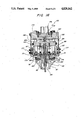
- FIG. 1 is a side view of the integrated circuit removal apparatus of the preferred embodiment
- FIG. 4 is a top view of a leveler plate according to the preferred embodiment
- FIG. 6 is a side view of the lower heat shield of FIG. 5;
- FIG. 7 is a top view of a shoe according to the preferred embodiment.
- FIG. 9 is a top view of the jaw of FIG. 8;
- FIG. 12 is a side, partially cutaway view of the base plate of FIG. 11;
- FIGS. 13A though 13E illustrate operation of the preferred embodiment
- FIG. 14 is a side view of an alternate embodiment
- FIG. 15 is a top view of an alternate embodiment
- the preferred embodiment comprises a gripper unit 12, which is typically mounted to a weld head mechanism which positions the gripper unit 12.
- the gripper unit 12 includes four gripper arms 11, each pivotally mounted by a roller bearing 13 to an upright pivot mount 14.
- the pivot mount is screwed via screws 16 into a base plate 18.
- Each gripper arm 11 is activated by a respective air cylinder 20, which is also screwed into the base plate 18.
- the range of gripper arm motion is approximately 0.125 inch.
- each gripper arm 11 includes a set screw 17 whose point abuts and pushes against a respective leveler plate 15.
- the set screws 17 provide a fine tuning adjustment to move the leveler plate 15 in and out slightly to accommodate slight variations in IC size on the order of 20/1000 to 30/1000-inch.
- a jaw 27 is attached to each shoe 19 by a screw 29.
- a heater element 31 and a thermocouple 33 are attached to each jaw 27.
- the lower end 34 of each jaw 27 is appropriately shaped to grip an integrated circuit package.
- the lower end 34 is provided with a projection designed to grip a J-lead device.
- each jaw end forms one side of a rectangle and thus may move in and grip a substantially square, rectangular, or two-sided IC package.
- respective outside flexure arms 35, 37 are attached between the leveler plate 15 and the base plate 18.
- a middle inner flexure arm 38 is attached between the apex 105 (FIG. 4) of the leveler plate 18 and the base plate 18.
- Each outside flexure arm 35, 37 is parallel to the inner flexure arm 38 and attached using the leveler plate holes 103, 104 shown in FIG. 4.
- the flexure arms 35, 37, 38 are constructed of spring steel of a thickness of 20/1000-inch.
- the arms 35, 37, 38 essentially suspend and hinge the leveler plate 15 at three points and provide and maintain parallelism between the leveler plate 15 and the base plate 18.
- pairs of the gripper arms 11 are located directly opposite one another and are symmetrically located about perpendicular center lines 40, 42 such that the jaws 27 may come together to form a square or rectangle.
- the operation of the foregoing structure may be briefly described as follows:
- the jaws 27 are first in an open state.
- the gripper unit 12 is then lowered by cooperating positioning apparatus so that the jaws 27 are positioned on the pads of the circuit board about the IC to be picked up.
- the air cylinders 20 are then appropriately activated, forcing the gripper arms 11 to pivot about the axes of their respective bearings 13.
- the gripper arms 11 in turn push the leveler plates 15 and the attached shoes 19 inward, simultaneously closing the jaws 27 about the integrated circuit package.
- only a pair of the air cylinders 20 need be activated, such that an IC with leads on two sides may be grasped and removed.
- a lower heat shield 55 of "L"-shaped cross-section is mounted about each shoe 19.
- An upper heat shield 65 is mounted above the lower heat shield 55.
- the upper heat shield 65 is a substantially square plate with appropriate apertures to accommodate various structural elements of the device which must pass through it.
- the upper and lower heat shields 55, 65 may be fabricated of 316 stainless steel. Without appropriate heat shielding, heat would take the temper out of various metal members, ruin springs in the device, melt plastic tubing and air cylinder 0-rings, and transfer up to and damage the weld head mechanism mounting the device.
- a cooling air and vacuum pickup structure 73 Within the jaw-activating structure is located a cooling air and vacuum pickup structure 73.
- This structure employs three concentric tubes 75, 77, 79.
- the first spring tube 75 mounts a vacuum quill 86.
- the spring tube 75 permits spring-loaded vertical movement of the vacuum quill 86 as it comes into contact with an integrated circuit package, and provides an inner passage 85 through which a vacuum may be applied to the orifice 81 of the vacuum quill 86.
- the second and third concentric tubes 77, 79 form an annular passage 83 through which an air purge is applied to cool the tubes 75, 77, 79, in order to prevent the spring of the spring tube 75 from losing its temper and to assist in solidifying solder.
- a vacuum is applied to the inner passage 85 through an inner port 91, while purge air is supplied to the annular passage 83 through a second inner port 93.
- the inner ports 91, 93 are supplied through respective external ports 95, 97 (FIG.
- a coupler 98 is employed to provide for rotation about the central axis of the gripper device 12 in order to align the gripper jaws 27 to a circuit board.
- the coupler 98 includes a flanged end 99 which is retained by a clamping collar 101 fastened in place by four screws 102.
- a wave washer 105 is also employed to facilitate rotation.
- a set screw 107 (FIG. 11) locks the rotation of the gripper unit 12 with respect to the coupler 98.
- FIGS. 4-7 illustrate the generally triangular structure of the sequentially attached leveler plate 15, lower heat shield 55 and shoe 19.
- four sets of leveler plates 15, lower heat shields 55 and shoes 9 are employed in the preferred embodiment for four-sided devices.
- Two gripper arms may be employed for certain two-sided devices.
- FIG. 4 illustrates screw holes 103, 104 at the apex 105 of the leveler plate 15, which accommodate screws which attach one of the middle inner flexure arms 38. Also shown are three threaded screw holes 108, 109, 111 near each corner of the leveler plate 15, which accept the screws 21 (FIGS. 1, 3). Another threaded screw hole 110 accommodates the set screw 25.
- the heat shield of FIGS. 5 and 6 also includes unthreaded holes 115, 117, 119 through which the screws 21 pass.
- the other hole 121 accommodates the ball bearing 23.
- the shoe 19 of FIG. 7 contains three threaded holes 123, 125, 127, which receive respective ones of the screws 21.
- the screw hole 129 in the cutout area 130 of the shoe 19 accepts the screw 29, which attaches one of the jaws 27 to the shoe 19.
- the screw 29 threads through a hole 131 in the jaw 27 as shown in FIGS. 8 and 9.
- a screw hole 133 (FIG. 10) in each jaw 27 mounts one of the thermocouple attachment screws 33 shown in FIG. 3.
- the base plate 18 is shown in further detail in FIGS. 11 and 12. Respective pairs of screw holes 135, 136; 137, 138; 139, 140; and 141, 142 are provided to receive the screws 16 which attach the upright pivot mounts 14. Near each corner 144 are located threaded holes 145 which receive screws 36 attaching the parallel outside flexure arms 35, 37.
- the cutaway area of FIG. 12 particularly shows successive inner cylindrical bores which receive the flanged end 99 and clamping collar 101, as well as the threaded holes 149 which receive the screws 102 of FIG. 3.
- FIG. 11 further shows a diagonal bore 148 which receives a set screw 107 for locking the rotation of the gripper flange 99 of the coupler 98.
- the threaded hole 153 of FIG. 12 receives one of the four screws 22 of FIG. 3, which attach the inner flexure arms 38.
- the soldering head 12 of the preferred embodiment is positioned over an IC 202 to be removed, as shown in FIG. 13A.
- the cavity formed by the four heater jaws 27 is then brought down around the IC 202 so that one face of each jaw 27 makes contact with the plane of the printed circuit board (PCB) 203, as shown in FIG. 13B.
- the jaws 27 actually touch down on pads 207 on the PCB 203.
- the air purge is on at all times, and the vacuum apparatus is activated upon touchdown on the PCB 203.
- FIG. 13C particularly shows the pivoted position of the gripper arms 11 and flexing of the flexure arms 35, 37, 38. Since the jaws 27 are likely to make their initial contact with solid solder, the downward and inward forces must typically be maintained through the liquefaction process. The inward and downward motion of the jaws 27 ceases when all of the solder has liquefied and the jaws 27 are halted by the solid, nonmelting leads of the IC 202 and the pads 207 of the PCB 203.
- the vertical component of force on the soldering head 12 is reversed, while the inward force is maintained to effectively grasp the device 202 during the lifting phase of the cycle, illustrated in FIG. 13D. Further, it may or may not be desirable, or required, to apply a rotary motion to the soldering head 12 in order to break any adhesive which might have been placed between the bottom of the IC 202 and the PCB 203.
- the jaws 27 are closed upon the IC 202. They remain closed until the IC 202 is removed from the PCB 203 and the mechanism reaches its upper limit. At the upper limit, the jaws 27 are opened and the IC 202 is held only by vacuum, as shown in FIG. 13E. The opening of the jaws, FIG. 13E, removes the IC 202 from direct thermal contact with the heating surfaces.
- FIGS. 13A-E particularly illustrate removal of a J-lead device.
- gripping action of the jaws 27 is not typically necessary. Instead, the jaws 27 typically may be touched down against the leads of the gull wing device, heat applied, and the circuit removed by the vacuum cup 86.
- the lower plate 163 is mounted to move vertically upward with respect to a base plate 173 utilizing four shoulder screws and bearings 164.
- a spring 175 biases the lower plate 163 at a distance away from the base plate 173, and an O-ring 170 is provided to provide a seal to maintain gripping action during circuit removal.
- a collar mechanism 174 similar to that of the preferred embodiment, is also provided.
- the base plate 173 mounts four leaf springs 182, each of which extends down the middle of each side of the device.
- Each leaf spring 182 mounts a cam follower 177, which mounts rollers 179.
- Each roller 179 is positioned to contact a rigid extension 181 of a respective heat shield 171 upon downward vertical motion of the roller 179.
- the extensions 181 serve as cam surfaces to create inward motion of the jaws 161.
- the soldering head 122 moves down until the lower portion of the head 183 is stopped by contact with the PCB.
- the base plate 173 is somewhat independent and continues downward for a short distance to make a seal between the O-ring 170 and the top of the lower plate 163. Then the vacuum is turned on to maintain gripping action on the integrated circuit.
- the additional motion of the base plate 173 is converted into inward forces by action of the leaf spring mounted rollers 179 contacting the cam surfaces on extensions 181. These inward forces serve to cause the jaws 161 to securely grasp a four-sided integrated circuit while heat is applied and the IC removed as in the preferred embodiment.
Abstract
Description
Claims (14)
Priority Applications (4)
| Application Number | Priority Date | Filing Date | Title |
|---|---|---|---|
| US07/161,862 US4828162A (en) | 1988-02-29 | 1988-02-29 | Moving jaw reflow soldering head |
| PCT/US1989/000282 WO1989008376A1 (en) | 1988-02-29 | 1989-01-23 | Moving jaw reflow soldering head |
| EP89902148A EP0360846A1 (en) | 1988-02-29 | 1989-01-23 | Moving jaw reflow soldering head |
| JP1502000A JPH02503847A (en) | 1988-02-29 | 1989-01-23 | Moving jaw remelting soldering head |
Applications Claiming Priority (1)
| Application Number | Priority Date | Filing Date | Title |
|---|---|---|---|
| US07/161,862 US4828162A (en) | 1988-02-29 | 1988-02-29 | Moving jaw reflow soldering head |
Publications (1)
| Publication Number | Publication Date |
|---|---|
| US4828162A true US4828162A (en) | 1989-05-09 |
Family
ID=22583092
Family Applications (1)
| Application Number | Title | Priority Date | Filing Date |
|---|---|---|---|
| US07/161,862 Expired - Lifetime US4828162A (en) | 1988-02-29 | 1988-02-29 | Moving jaw reflow soldering head |
Country Status (4)
| Country | Link |
|---|---|
| US (1) | US4828162A (en) |
| EP (1) | EP0360846A1 (en) |
| JP (1) | JPH02503847A (en) |
| WO (1) | WO1989008376A1 (en) |
Cited By (27)
| Publication number | Priority date | Publication date | Assignee | Title |
|---|---|---|---|---|
| US4967058A (en) * | 1988-04-13 | 1990-10-30 | Kabushiki Kaisha Toshiba | Power heating member |
| US5068508A (en) * | 1990-10-01 | 1991-11-26 | Raytheon Company | Complaint hot bar apparatus |
| US5102028A (en) * | 1990-04-02 | 1992-04-07 | International Business Machines Corporation | Localized soldering station using state changing medium |
| US5145101A (en) * | 1991-06-05 | 1992-09-08 | Pace Incorporated | Tweezer handpiece for installation and removal of electronic components with respect to a substrate and tips and tool for use therewith |
| US5164037A (en) * | 1991-05-08 | 1992-11-17 | Hughes Aircraft Company | Apparatus for removing semiconductor devices from high density multichip modules |
| US5172469A (en) * | 1991-05-08 | 1992-12-22 | Hughes Aircraft Company | Advanced part removal and torque shear station |
| US5174016A (en) * | 1991-04-25 | 1992-12-29 | Toddco General, Inc. | Chip removal apparatus and method of using same |
| US5211325A (en) * | 1991-06-26 | 1993-05-18 | Siemens Nixdorf Informationssysteme Ag | Method and apparatus for soldering surface-mountable components to a printed circuit board |
| US5246157A (en) * | 1991-06-05 | 1993-09-21 | Pace, Incorporated | Tool for use with tweezer handpiece for installation and removal of electronic components with respect to a substrate |
| US5291217A (en) * | 1990-05-29 | 1994-03-01 | Eastman Kodak Company | Method and apparatus for producing thermal slide transparencies |
| US5297717A (en) * | 1993-04-05 | 1994-03-29 | Pace Incorporated | Self-aligning tip elements for tweezer-type soldering handpiece |
| US5516030A (en) * | 1994-07-20 | 1996-05-14 | Compaq Computer Corporation | Method and apparatus for assembling ball grid array components on printed circuit boards by reflowing before placement |
| US5549240A (en) * | 1995-02-14 | 1996-08-27 | Cooper Industries, Inc. | Surface mount device removal tool |
| US5579979A (en) * | 1993-03-29 | 1996-12-03 | Cooper Industries, Inc. | Soldering/desoldering nozzles for SMD's |
| US5724728A (en) * | 1994-11-29 | 1998-03-10 | Sgs-Thomson Microelectronics, Inc. | Method of mounting an integrated circuit to a mounting surface |
| US5938882A (en) * | 1997-09-30 | 1999-08-17 | Harris Corporation | Method for removing microelectronic circuits from substrates and tool used in removal |
| US6016949A (en) * | 1997-07-01 | 2000-01-25 | International Business Machines Corporation | Integrated placement and soldering pickup head and method of using |
| US6288365B1 (en) * | 1999-05-18 | 2001-09-11 | Mcammond Matthew J. | Soldering assembly |
| US20040099709A1 (en) * | 2002-11-25 | 2004-05-27 | Primax Electronics Ltd. | Griper and method for detaching packaged chip from PCB |
| US20060107513A1 (en) * | 2004-11-19 | 2006-05-25 | Fujitsu Limited | Method of removing integrated circuit chip package and detachment jig therefor |
| WO2006058324A1 (en) * | 2004-11-29 | 2006-06-01 | Heetronix Corp. | Thermal attach and detach methods and systems for surface-mounted components |
| US20080156789A1 (en) * | 2004-11-29 | 2008-07-03 | Andrew Devey | Platen for use with a thermal attach and detach system which holds components by vacuum suction |
| US20090165292A1 (en) * | 2007-12-28 | 2009-07-02 | Jonathan Amurao | Integrated circuit dismounter |
| TWI386571B (en) * | 2010-10-22 | 2013-02-21 | Mfc Sealing Technology Company Ltd | Magnetic sets of spring fixture |
| US20130108501A1 (en) * | 2005-09-29 | 2013-05-02 | Dow Corning Corporation | Method of Releasing High Temperature Films and/or Devices From Metallic Substrates |
| US20130292455A1 (en) * | 2012-05-03 | 2013-11-07 | International Business Machines Corporation | Flip chip assembly apparatus employing a warpage-suppressor assembly |
| US20160353623A1 (en) * | 2015-06-01 | 2016-12-01 | Boe Technology Group Co., Ltd. | Integrated circuit chip extractor and method for operating the same |
Citations (47)
| Publication number | Priority date | Publication date | Assignee | Title |
|---|---|---|---|---|
| US3230338A (en) * | 1962-07-02 | 1966-01-18 | Ibm | Selective heating apparatus |
| US3382564A (en) * | 1965-09-27 | 1968-05-14 | Gen Dynamics Corp | Soldering apparatus and method for microelectronic circuits |
| US3529760A (en) * | 1968-01-24 | 1970-09-22 | Radiation Inc | Flatpack installation and removal tool |
| DE1943393A1 (en) * | 1969-08-26 | 1971-03-04 | Siemens Ag | Device for loosening, in particular, multi-pole electrical components from their carrier plate |
| US3576969A (en) * | 1969-09-02 | 1971-05-04 | Ibm | Solder reflow device |
| US3632973A (en) * | 1970-06-01 | 1972-01-04 | Honeywell Inf Systems | Soldering tool for removal and replacement of components having multiple soldered junctions |
| US3649809A (en) * | 1971-04-19 | 1972-03-14 | William Meredith Halstead | Soldering and de-soldering tip for connector pins of electrical components |
| US3673384A (en) * | 1970-11-02 | 1972-06-27 | Burroughs Corp | Integrated circuit extractor tool |
| US3700155A (en) * | 1970-05-20 | 1972-10-24 | Mech El Ind Inc | Apparatus for improving alignment of beam leaded bonding tools |
| US3746239A (en) * | 1970-11-12 | 1973-07-17 | D Auray | Desoldering device |
| US3791018A (en) * | 1971-11-16 | 1974-02-12 | Western Electric Co | Heating method and apparatus for securing a member to an article |
| US3804320A (en) * | 1972-09-13 | 1974-04-16 | Nu Concept Computer Syst Inc | Pack extractor |
| US3813023A (en) * | 1972-12-04 | 1974-05-28 | D Auray | Desoldering device |
| US3883945A (en) * | 1974-03-13 | 1975-05-20 | Mallory & Co Inc P R | Method for transferring and joining beam leaded chips |
| SU471966A1 (en) * | 1973-06-21 | 1975-05-30 | Предприятие П/Я Р-6255 | IC soldering device |
| US3887783A (en) * | 1972-11-09 | 1975-06-03 | Honeywell Bull Sa | Devices for welding of integrated-circuit wafers |
| US3990863A (en) * | 1974-08-01 | 1976-11-09 | Palmer Harold D | Integrated-circuit block extraction tool |
| US4013208A (en) * | 1976-03-08 | 1977-03-22 | The Singer Company | Soldering mechanism for soldering electronic component leads to conductors on a printed circuit board, and the like |
| US4022370A (en) * | 1976-04-30 | 1977-05-10 | Burroughs Corporation | Dual in-line chip extractor-exchanger apparatus |
| US4034202A (en) * | 1975-05-23 | 1977-07-05 | Nu-Concept Computer Systems, Inc. | Integrated circuit pack extractor |
| US4084315A (en) * | 1976-12-30 | 1978-04-18 | Honeywell Information Systems Inc. | Fixture for soldering integrated circuit chips to a multilayer substrate |
| US4135630A (en) * | 1977-12-08 | 1979-01-23 | Universal Instruments Corporation | Centering device for automatic placement of chip components in hybrid circuits |
| US4136444A (en) * | 1977-06-06 | 1979-01-30 | Burroughs Corporation | Semiautomatic solid chip removal apparatus |
| SU670399A1 (en) * | 1977-04-01 | 1979-06-30 | Предприятие П/Я А-7438 | Microcircuit board soldering apparatus |
| JPS5524776A (en) * | 1978-08-14 | 1980-02-22 | Hitachi Ltd | Roll changing apparatus at multi-step rolling mill |
| JPS5582444A (en) * | 1978-12-15 | 1980-06-21 | Nec Home Electronics Ltd | Manufacture of semiconductor device |
| US4255644A (en) * | 1977-04-29 | 1981-03-10 | Compagnie Internationale L'informatique-Cuu Honeywell Bull | Micro-soldering tool |
| US4295596A (en) * | 1979-12-19 | 1981-10-20 | Western Electric Company, Inc. | Methods and apparatus for bonding an article to a metallized substrate |
| US4300715A (en) * | 1977-09-01 | 1981-11-17 | The Jade Corporation | Mechanical pulse reflow bonding process |
| SU912421A1 (en) * | 1980-04-11 | 1982-03-15 | Предприятие П/Я А-7220 | Apparatus for soldering microcircuits |
| US4381601A (en) * | 1978-11-09 | 1983-05-03 | Tokyo Shibaura Denki Kabushiki Kaisha | Apparatus for mounting electronic components |
| US4399610A (en) * | 1981-04-01 | 1983-08-23 | Western Electric Company, Inc. | Assembling an electronic device |
| US4431474A (en) * | 1982-08-13 | 1984-02-14 | Western Electric Company, Inc. | Thermocompression bonding apparatus |
| US4436242A (en) * | 1981-12-15 | 1984-03-13 | Rca Corporation | Desoldering tool and method of desoldering leadless components |
| US4500032A (en) * | 1983-02-16 | 1985-02-19 | Universal Instruments Corporation | Method and apparatus for proper registration of mating parts |
| US4507861A (en) * | 1983-12-12 | 1985-04-02 | Burroughs Corporation | Insertion device for an electronic circuit package assembly |
| US4518110A (en) * | 1982-09-22 | 1985-05-21 | Control Data Corporation | Device for soldering/desoldering apertured lendless packages |
| US4521959A (en) * | 1983-07-05 | 1985-06-11 | Burroughs Corporation | Device for the controlled extraction of electronic circuit components |
| US4528746A (en) * | 1982-08-31 | 1985-07-16 | Hakko Metal Industries Limited | Device for dismounting integrated circuit devices |
| US4552300A (en) * | 1983-05-09 | 1985-11-12 | Pace, Incorporated | Method and apparatus for soldering and desoldering leadless semiconductor modules for printed wiring boards |
| US4599037A (en) * | 1984-07-02 | 1986-07-08 | United Technologies Corporation | Method and apparatus for manipulating miniature parts |
| US4607782A (en) * | 1985-05-24 | 1986-08-26 | Contact Systems, Inc. | Method and apparatus for soldering electrical components to circuit boards |
| US4614858A (en) * | 1985-03-28 | 1986-09-30 | Hewlett Packard Company | Electric tool for desoldering surface mounted devices |
| US4654507A (en) * | 1985-05-07 | 1987-03-31 | Hughes Aircraft Company | Solder reflow heater bar assembly |
| GB2185432A (en) * | 1986-01-17 | 1987-07-22 | Fujitsu Ltd | Reflow bonding of electronic or electrical parts |
| US4694570A (en) * | 1985-11-21 | 1987-09-22 | Amistar Corporation | Surface mounted component transport mechanism |
| US4696096A (en) * | 1986-02-21 | 1987-09-29 | Micro Electronic Systems, Inc. | Reworking methods and apparatus for surface mounted technology circuit boards |
-
1988
- 1988-02-29 US US07/161,862 patent/US4828162A/en not_active Expired - Lifetime
-
1989
- 1989-01-23 JP JP1502000A patent/JPH02503847A/en active Pending
- 1989-01-23 WO PCT/US1989/000282 patent/WO1989008376A1/en not_active Application Discontinuation
- 1989-01-23 EP EP89902148A patent/EP0360846A1/en not_active Withdrawn
Patent Citations (48)
| Publication number | Priority date | Publication date | Assignee | Title |
|---|---|---|---|---|
| US3230338A (en) * | 1962-07-02 | 1966-01-18 | Ibm | Selective heating apparatus |
| US3382564A (en) * | 1965-09-27 | 1968-05-14 | Gen Dynamics Corp | Soldering apparatus and method for microelectronic circuits |
| US3529760A (en) * | 1968-01-24 | 1970-09-22 | Radiation Inc | Flatpack installation and removal tool |
| DE1943393A1 (en) * | 1969-08-26 | 1971-03-04 | Siemens Ag | Device for loosening, in particular, multi-pole electrical components from their carrier plate |
| US3576969A (en) * | 1969-09-02 | 1971-05-04 | Ibm | Solder reflow device |
| US3700155A (en) * | 1970-05-20 | 1972-10-24 | Mech El Ind Inc | Apparatus for improving alignment of beam leaded bonding tools |
| US3632973A (en) * | 1970-06-01 | 1972-01-04 | Honeywell Inf Systems | Soldering tool for removal and replacement of components having multiple soldered junctions |
| US3673384A (en) * | 1970-11-02 | 1972-06-27 | Burroughs Corp | Integrated circuit extractor tool |
| US3746239A (en) * | 1970-11-12 | 1973-07-17 | D Auray | Desoldering device |
| US3649809A (en) * | 1971-04-19 | 1972-03-14 | William Meredith Halstead | Soldering and de-soldering tip for connector pins of electrical components |
| US3791018A (en) * | 1971-11-16 | 1974-02-12 | Western Electric Co | Heating method and apparatus for securing a member to an article |
| US3804320A (en) * | 1972-09-13 | 1974-04-16 | Nu Concept Computer Syst Inc | Pack extractor |
| US3887783A (en) * | 1972-11-09 | 1975-06-03 | Honeywell Bull Sa | Devices for welding of integrated-circuit wafers |
| US3813023A (en) * | 1972-12-04 | 1974-05-28 | D Auray | Desoldering device |
| SU471966A1 (en) * | 1973-06-21 | 1975-05-30 | Предприятие П/Я Р-6255 | IC soldering device |
| US3883945A (en) * | 1974-03-13 | 1975-05-20 | Mallory & Co Inc P R | Method for transferring and joining beam leaded chips |
| US3990863A (en) * | 1974-08-01 | 1976-11-09 | Palmer Harold D | Integrated-circuit block extraction tool |
| US4034202A (en) * | 1975-05-23 | 1977-07-05 | Nu-Concept Computer Systems, Inc. | Integrated circuit pack extractor |
| US4013208A (en) * | 1976-03-08 | 1977-03-22 | The Singer Company | Soldering mechanism for soldering electronic component leads to conductors on a printed circuit board, and the like |
| US4022370A (en) * | 1976-04-30 | 1977-05-10 | Burroughs Corporation | Dual in-line chip extractor-exchanger apparatus |
| US4084315A (en) * | 1976-12-30 | 1978-04-18 | Honeywell Information Systems Inc. | Fixture for soldering integrated circuit chips to a multilayer substrate |
| SU670399A1 (en) * | 1977-04-01 | 1979-06-30 | Предприятие П/Я А-7438 | Microcircuit board soldering apparatus |
| US4255644A (en) * | 1977-04-29 | 1981-03-10 | Compagnie Internationale L'informatique-Cuu Honeywell Bull | Micro-soldering tool |
| US4136444A (en) * | 1977-06-06 | 1979-01-30 | Burroughs Corporation | Semiautomatic solid chip removal apparatus |
| US4300715A (en) * | 1977-09-01 | 1981-11-17 | The Jade Corporation | Mechanical pulse reflow bonding process |
| US4135630A (en) * | 1977-12-08 | 1979-01-23 | Universal Instruments Corporation | Centering device for automatic placement of chip components in hybrid circuits |
| JPS5524776A (en) * | 1978-08-14 | 1980-02-22 | Hitachi Ltd | Roll changing apparatus at multi-step rolling mill |
| US4381601A (en) * | 1978-11-09 | 1983-05-03 | Tokyo Shibaura Denki Kabushiki Kaisha | Apparatus for mounting electronic components |
| JPS5582444A (en) * | 1978-12-15 | 1980-06-21 | Nec Home Electronics Ltd | Manufacture of semiconductor device |
| US4295596A (en) * | 1979-12-19 | 1981-10-20 | Western Electric Company, Inc. | Methods and apparatus for bonding an article to a metallized substrate |
| SU912421A1 (en) * | 1980-04-11 | 1982-03-15 | Предприятие П/Я А-7220 | Apparatus for soldering microcircuits |
| US4399610A (en) * | 1981-04-01 | 1983-08-23 | Western Electric Company, Inc. | Assembling an electronic device |
| US4399610B1 (en) * | 1981-04-01 | 1992-11-03 | At & T Technologies Inc | |
| US4436242A (en) * | 1981-12-15 | 1984-03-13 | Rca Corporation | Desoldering tool and method of desoldering leadless components |
| US4431474A (en) * | 1982-08-13 | 1984-02-14 | Western Electric Company, Inc. | Thermocompression bonding apparatus |
| US4528746A (en) * | 1982-08-31 | 1985-07-16 | Hakko Metal Industries Limited | Device for dismounting integrated circuit devices |
| US4518110A (en) * | 1982-09-22 | 1985-05-21 | Control Data Corporation | Device for soldering/desoldering apertured lendless packages |
| US4500032A (en) * | 1983-02-16 | 1985-02-19 | Universal Instruments Corporation | Method and apparatus for proper registration of mating parts |
| US4552300A (en) * | 1983-05-09 | 1985-11-12 | Pace, Incorporated | Method and apparatus for soldering and desoldering leadless semiconductor modules for printed wiring boards |
| US4521959A (en) * | 1983-07-05 | 1985-06-11 | Burroughs Corporation | Device for the controlled extraction of electronic circuit components |
| US4507861A (en) * | 1983-12-12 | 1985-04-02 | Burroughs Corporation | Insertion device for an electronic circuit package assembly |
| US4599037A (en) * | 1984-07-02 | 1986-07-08 | United Technologies Corporation | Method and apparatus for manipulating miniature parts |
| US4614858A (en) * | 1985-03-28 | 1986-09-30 | Hewlett Packard Company | Electric tool for desoldering surface mounted devices |
| US4654507A (en) * | 1985-05-07 | 1987-03-31 | Hughes Aircraft Company | Solder reflow heater bar assembly |
| US4607782A (en) * | 1985-05-24 | 1986-08-26 | Contact Systems, Inc. | Method and apparatus for soldering electrical components to circuit boards |
| US4694570A (en) * | 1985-11-21 | 1987-09-22 | Amistar Corporation | Surface mounted component transport mechanism |
| GB2185432A (en) * | 1986-01-17 | 1987-07-22 | Fujitsu Ltd | Reflow bonding of electronic or electrical parts |
| US4696096A (en) * | 1986-02-21 | 1987-09-29 | Micro Electronic Systems, Inc. | Reworking methods and apparatus for surface mounted technology circuit boards |
Cited By (35)
| Publication number | Priority date | Publication date | Assignee | Title |
|---|---|---|---|---|
| US4967058A (en) * | 1988-04-13 | 1990-10-30 | Kabushiki Kaisha Toshiba | Power heating member |
| US5102028A (en) * | 1990-04-02 | 1992-04-07 | International Business Machines Corporation | Localized soldering station using state changing medium |
| US5291217A (en) * | 1990-05-29 | 1994-03-01 | Eastman Kodak Company | Method and apparatus for producing thermal slide transparencies |
| US5068508A (en) * | 1990-10-01 | 1991-11-26 | Raytheon Company | Complaint hot bar apparatus |
| US5174016A (en) * | 1991-04-25 | 1992-12-29 | Toddco General, Inc. | Chip removal apparatus and method of using same |
| US5172469A (en) * | 1991-05-08 | 1992-12-22 | Hughes Aircraft Company | Advanced part removal and torque shear station |
| US5164037A (en) * | 1991-05-08 | 1992-11-17 | Hughes Aircraft Company | Apparatus for removing semiconductor devices from high density multichip modules |
| US5246157A (en) * | 1991-06-05 | 1993-09-21 | Pace, Incorporated | Tool for use with tweezer handpiece for installation and removal of electronic components with respect to a substrate |
| US5145101A (en) * | 1991-06-05 | 1992-09-08 | Pace Incorporated | Tweezer handpiece for installation and removal of electronic components with respect to a substrate and tips and tool for use therewith |
| US5211325A (en) * | 1991-06-26 | 1993-05-18 | Siemens Nixdorf Informationssysteme Ag | Method and apparatus for soldering surface-mountable components to a printed circuit board |
| US5579979A (en) * | 1993-03-29 | 1996-12-03 | Cooper Industries, Inc. | Soldering/desoldering nozzles for SMD's |
| US5297717A (en) * | 1993-04-05 | 1994-03-29 | Pace Incorporated | Self-aligning tip elements for tweezer-type soldering handpiece |
| US5516030A (en) * | 1994-07-20 | 1996-05-14 | Compaq Computer Corporation | Method and apparatus for assembling ball grid array components on printed circuit boards by reflowing before placement |
| US5724728A (en) * | 1994-11-29 | 1998-03-10 | Sgs-Thomson Microelectronics, Inc. | Method of mounting an integrated circuit to a mounting surface |
| US5549240A (en) * | 1995-02-14 | 1996-08-27 | Cooper Industries, Inc. | Surface mount device removal tool |
| US6016949A (en) * | 1997-07-01 | 2000-01-25 | International Business Machines Corporation | Integrated placement and soldering pickup head and method of using |
| US5938882A (en) * | 1997-09-30 | 1999-08-17 | Harris Corporation | Method for removing microelectronic circuits from substrates and tool used in removal |
| US6288365B1 (en) * | 1999-05-18 | 2001-09-11 | Mcammond Matthew J. | Soldering assembly |
| US6335514B2 (en) * | 1999-05-18 | 2002-01-01 | Assembly Technologies Int., Inc. | Soldering assembly |
| US20040099709A1 (en) * | 2002-11-25 | 2004-05-27 | Primax Electronics Ltd. | Griper and method for detaching packaged chip from PCB |
| US7004371B2 (en) * | 2002-11-25 | 2006-02-28 | Primax Electronics Ltd. | Gripper and method for detaching packaged chip from PCB |
| US20060107513A1 (en) * | 2004-11-19 | 2006-05-25 | Fujitsu Limited | Method of removing integrated circuit chip package and detachment jig therefor |
| US7469457B2 (en) * | 2004-11-19 | 2008-12-30 | Fujitsu Limited | Method of removing integrated circuit chip package and detachment jig therefor |
| US20080156789A1 (en) * | 2004-11-29 | 2008-07-03 | Andrew Devey | Platen for use with a thermal attach and detach system which holds components by vacuum suction |
| US20060131360A1 (en) * | 2004-11-29 | 2006-06-22 | Heetronix Corp. | Thermal attach and detach methods and system for surface-mounted components |
| WO2006058324A1 (en) * | 2004-11-29 | 2006-06-01 | Heetronix Corp. | Thermal attach and detach methods and systems for surface-mounted components |
| US20130108501A1 (en) * | 2005-09-29 | 2013-05-02 | Dow Corning Corporation | Method of Releasing High Temperature Films and/or Devices From Metallic Substrates |
| US20090165292A1 (en) * | 2007-12-28 | 2009-07-02 | Jonathan Amurao | Integrated circuit dismounter |
| US7836583B2 (en) * | 2007-12-28 | 2010-11-23 | Hitachi Global Storage Technologies, Netherlands, B.V. | Integrated circuit dismounter |
| TWI386571B (en) * | 2010-10-22 | 2013-02-21 | Mfc Sealing Technology Company Ltd | Magnetic sets of spring fixture |
| US20130292455A1 (en) * | 2012-05-03 | 2013-11-07 | International Business Machines Corporation | Flip chip assembly apparatus employing a warpage-suppressor assembly |
| US8870051B2 (en) * | 2012-05-03 | 2014-10-28 | International Business Machines Corporation | Flip chip assembly apparatus employing a warpage-suppressor assembly |
| US8978960B2 (en) | 2012-05-03 | 2015-03-17 | International Business Machines Corporation | Flip chip assembly apparatus employing a warpage-suppressor assembly |
| US20160353623A1 (en) * | 2015-06-01 | 2016-12-01 | Boe Technology Group Co., Ltd. | Integrated circuit chip extractor and method for operating the same |
| US10219420B2 (en) * | 2015-06-01 | 2019-02-26 | Boe Technology Group Co., Ltd. | Integrated circuit chip extractor |
Also Published As
| Publication number | Publication date |
|---|---|
| EP0360846A1 (en) | 1990-04-04 |
| WO1989008376A1 (en) | 1989-09-08 |
| JPH02503847A (en) | 1990-11-08 |
Similar Documents
| Publication | Publication Date | Title |
|---|---|---|
| US4828162A (en) | Moving jaw reflow soldering head | |
| US6030889A (en) | Substrate-holding fixture of non-wettable material | |
| US4607779A (en) | Non-impact thermocompression gang bonding method | |
| US5878942A (en) | Soldering method and soldering apparatus | |
| US4934582A (en) | Method and apparatus for removing solder mounted electronic components | |
| JP2000260815A (en) | Method of melting bump, melting apparatus and method of producing semiconductor device | |
| US5549240A (en) | Surface mount device removal tool | |
| US4632294A (en) | Process and apparatus for individual pin repair in a dense array of connector pins of an electronic packaging structure | |
| US6016949A (en) | Integrated placement and soldering pickup head and method of using | |
| US6605500B2 (en) | Assembly process | |
| US20190099820A1 (en) | Apparatus, system, and method for mitigating warpage of circuit boards during reflow processes | |
| JPH06124953A (en) | Bump forming method of semiconductor device | |
| US6942137B2 (en) | Die removal method and apparatus | |
| US5068508A (en) | Complaint hot bar apparatus | |
| US5051555A (en) | Hot-bar suspension system | |
| JP2510688B2 (en) | Excess solder removal equipment | |
| CN108581921B (en) | Disassembling jig for large-size BGA (ball grid array) packaged chip and control method thereof | |
| US5520733A (en) | Deposition apparatus and profile-following device suitable for apparatuses such as those for deposition | |
| JPH0685447A (en) | Mount connecting method and device of electronic part | |
| JPH0831691B2 (en) | How to replace electronic components | |
| US6491205B1 (en) | Assembly of multi-chip modules using eutectic solders | |
| JPS5939040A (en) | Remover for part of chip | |
| JPH04338657A (en) | Connecting structure connecting method and connecting device between chip part and substrate | |
| JPH11145193A (en) | Method for forming soldered bump | |
| JP2001223464A (en) | Soldering method |
Legal Events
| Date | Code | Title | Description |
|---|---|---|---|
| AS | Assignment |
Owner name: HUGHES AIRCRAFT COMPANY, LOS ANGELES, CA, A DE COR Free format text: ASSIGNMENT OF ASSIGNORS INTEREST.;ASSIGNORS:DONNER, JOSEPH E.;JENSEN, WAYNE P.;REEL/FRAME:004846/0243 Effective date: 19880229 Owner name: HUGHES AIRCRAFT COMPANY,CALIFORNIA Free format text: ASSIGNMENT OF ASSIGNORS INTEREST;ASSIGNORS:DONNER, JOSEPH E.;JENSEN, WAYNE P.;REEL/FRAME:004846/0243 Effective date: 19880229 |
|
| STCF | Information on status: patent grant |
Free format text: PATENTED CASE |
|
| REMI | Maintenance fee reminder mailed | ||
| REMI | Maintenance fee reminder mailed | ||
| FPAY | Fee payment |
Year of fee payment: 4 |
|
| SULP | Surcharge for late payment | ||
| AS | Assignment |
Owner name: PALOMAR TECHNOLOGIES CORPORATION, CALIFORNIA Free format text: ASSIGNMENT OF ASSIGNORS INTEREST;ASSIGNOR:HUGHES AIRCRAFT COMPANY;REEL/FRAME:007715/0955 Effective date: 19951006 |
|
| FEPP | Fee payment procedure |
Free format text: PAT HOLDER CLAIMS SMALL ENTITY STATUS - SMALL BUSINESS (ORIGINAL EVENT CODE: SM02); ENTITY STATUS OF PATENT OWNER: LARGE ENTITY |
|
| AS | Assignment |
Owner name: CHEMICAL BANK, AS AGENT, NEW YORK Free format text: ASSIGNMENT FOR SECURITY;ASSIGNOR:PALOMAR TECHNOLOGIES CORPORATION;REEL/FRAME:007603/0481 Effective date: 19951006 |
|
| FPAY | Fee payment |
Year of fee payment: 8 |
|
| FEPP | Fee payment procedure |
Free format text: PAT HLDR NO LONGER CLAIMS SMALL ENT STAT AS SMALL BUSINESS (ORIGINAL EVENT CODE: LSM2); ENTITY STATUS OF PATENT OWNER: LARGE ENTITY |
|
| FPAY | Fee payment |
Year of fee payment: 12 |
|
| AS | Assignment |
Owner name: PALOMAR TECHNOLOGIES, INC., CALIFORNIA Free format text: ASSIGNMENT OF ASSIGNORS INTEREST;ASSIGNOR:PALOMAR TECHNOLOGIES CORPORATION;REEL/FRAME:011425/0755 Effective date: 20001218 |
|
| AS | Assignment |
Owner name: UNITEK MIYACHI INTERNATIONAL, LTD., CALIFORNIA Free format text: ASSIGNMENT OF ASSIGNORS INTEREST;ASSIGNOR:PALOMAR TECHNOLOGIES, INC.;REEL/FRAME:013269/0057 Effective date: 20020801 |
|
| AS | Assignment |
Owner name: UNITEK MIYACHI CORPORATION, CALIFORNIA Free format text: CHANGE OF NAME;ASSIGNOR:UNITEK MIYACHI INTERNATIONAL, LTD.;REEL/FRAME:016769/0442 Effective date: 20030804 Owner name: MIYACHI UNITEK CORPORATION, CALIFORNIA Free format text: CHANGE OF NAME;ASSIGNOR:UNITEK MIYACHI CORPORATION;REEL/FRAME:016769/0434 Effective date: 20050328 |