US4831457A - Image forming apparatus - Google Patents
Image forming apparatus Download PDFInfo
- Publication number
- US4831457A US4831457A US07/092,323 US9232387A US4831457A US 4831457 A US4831457 A US 4831457A US 9232387 A US9232387 A US 9232387A US 4831457 A US4831457 A US 4831457A
- Authority
- US
- United States
- Prior art keywords
- image forming
- image
- document
- unit
- scanning
- Prior art date
- Legal status (The legal status is an assumption and is not a legal conclusion. Google has not performed a legal analysis and makes no representation as to the accuracy of the status listed.)
- Expired - Lifetime
Links
- 230000008878 coupling Effects 0.000 claims description 26
- 238000010168 coupling process Methods 0.000 claims description 26
- 238000005859 coupling reaction Methods 0.000 claims description 26
- 230000007246 mechanism Effects 0.000 claims description 22
- 238000003384 imaging method Methods 0.000 claims description 13
- 230000001360 synchronised effect Effects 0.000 claims 1
- 230000004048 modification Effects 0.000 description 17
- 238000012986 modification Methods 0.000 description 17
- 230000015572 biosynthetic process Effects 0.000 description 9
- 230000009467 reduction Effects 0.000 description 4
- 239000011521 glass Substances 0.000 description 3
- 238000009434 installation Methods 0.000 description 3
- 238000010586 diagram Methods 0.000 description 2
- 230000006870 function Effects 0.000 description 2
- 230000003287 optical effect Effects 0.000 description 2
- 230000001902 propagating effect Effects 0.000 description 2
- 238000010438 heat treatment Methods 0.000 description 1
- 238000005549 size reduction Methods 0.000 description 1
- 238000004804 winding Methods 0.000 description 1
Images


Classifications
-
- H—ELECTRICITY
- H04—ELECTRIC COMMUNICATION TECHNIQUE
- H04N—PICTORIAL COMMUNICATION, e.g. TELEVISION
- H04N1/00—Scanning, transmission or reproduction of documents or the like, e.g. facsimile transmission; Details thereof
- H04N1/0035—User-machine interface; Control console
- H04N1/00352—Input means
-
- G—PHYSICS
- G03—PHOTOGRAPHY; CINEMATOGRAPHY; ANALOGOUS TECHNIQUES USING WAVES OTHER THAN OPTICAL WAVES; ELECTROGRAPHY; HOLOGRAPHY
- G03G—ELECTROGRAPHY; ELECTROPHOTOGRAPHY; MAGNETOGRAPHY
- G03G15/00—Apparatus for electrographic processes using a charge pattern
- G03G15/50—Machine control of apparatus for electrographic processes using a charge pattern, e.g. regulating differents parts of the machine, multimode copiers, microprocessor control
- G03G15/5016—User-machine interface; Display panels; Control console
-
- G—PHYSICS
- G06—COMPUTING; CALCULATING OR COUNTING
- G06F—ELECTRIC DIGITAL DATA PROCESSING
- G06F3/00—Input arrangements for transferring data to be processed into a form capable of being handled by the computer; Output arrangements for transferring data from processing unit to output unit, e.g. interface arrangements
- G06F3/01—Input arrangements or combined input and output arrangements for interaction between user and computer
- G06F3/02—Input arrangements using manually operated switches, e.g. using keyboards or dials
- G06F3/0202—Constructional details or processes of manufacture of the input device
- G06F3/021—Arrangements integrating additional peripherals in a keyboard, e.g. card or barcode reader, optical scanner
-
- H—ELECTRICITY
- H04—ELECTRIC COMMUNICATION TECHNIQUE
- H04N—PICTORIAL COMMUNICATION, e.g. TELEVISION
- H04N1/00—Scanning, transmission or reproduction of documents or the like, e.g. facsimile transmission; Details thereof
- H04N1/0035—User-machine interface; Control console
- H04N1/00352—Input means
- H04N1/00384—Key input means, e.g. buttons or keypads
-
- H—ELECTRICITY
- H04—ELECTRIC COMMUNICATION TECHNIQUE
- H04N—PICTORIAL COMMUNICATION, e.g. TELEVISION
- H04N1/00—Scanning, transmission or reproduction of documents or the like, e.g. facsimile transmission; Details thereof
- H04N1/0035—User-machine interface; Control console
- H04N1/00352—Input means
- H04N1/00397—Switches, knobs or the like
-
- H—ELECTRICITY
- H04—ELECTRIC COMMUNICATION TECHNIQUE
- H04N—PICTORIAL COMMUNICATION, e.g. TELEVISION
- H04N1/00—Scanning, transmission or reproduction of documents or the like, e.g. facsimile transmission; Details thereof
- H04N1/0035—User-machine interface; Control console
- H04N1/00405—Output means
- H04N1/0049—Output means providing a visual indication to the user, e.g. using a lamp
-
- H—ELECTRICITY
- H04—ELECTRIC COMMUNICATION TECHNIQUE
- H04N—PICTORIAL COMMUNICATION, e.g. TELEVISION
- H04N1/00—Scanning, transmission or reproduction of documents or the like, e.g. facsimile transmission; Details thereof
- H04N1/00519—Constructional details not otherwise provided for, e.g. housings, covers
- H04N1/00525—Providing a more compact apparatus, e.g. sheet discharge tray in cover
-
- H—ELECTRICITY
- H04—ELECTRIC COMMUNICATION TECHNIQUE
- H04N—PICTORIAL COMMUNICATION, e.g. TELEVISION
- H04N1/00—Scanning, transmission or reproduction of documents or the like, e.g. facsimile transmission; Details thereof
- H04N1/00519—Constructional details not otherwise provided for, e.g. housings, covers
- H04N1/00551—Top covers or the like
-
- H—ELECTRICITY
- H04—ELECTRIC COMMUNICATION TECHNIQUE
- H04N—PICTORIAL COMMUNICATION, e.g. TELEVISION
- H04N1/00—Scanning, transmission or reproduction of documents or the like, e.g. facsimile transmission; Details thereof
- H04N1/04—Scanning arrangements, i.e. arrangements for the displacement of active reading or reproducing elements relative to the original or reproducing medium, or vice versa
- H04N1/10—Scanning arrangements, i.e. arrangements for the displacement of active reading or reproducing elements relative to the original or reproducing medium, or vice versa using flat picture-bearing surfaces
- H04N1/1013—Scanning arrangements, i.e. arrangements for the displacement of active reading or reproducing elements relative to the original or reproducing medium, or vice versa using flat picture-bearing surfaces with sub-scanning by translatory movement of at least a part of the main-scanning components
- H04N1/1017—Scanning arrangements, i.e. arrangements for the displacement of active reading or reproducing elements relative to the original or reproducing medium, or vice versa using flat picture-bearing surfaces with sub-scanning by translatory movement of at least a part of the main-scanning components the main-scanning components remaining positionally invariant with respect to one another in the sub-scanning direction
-
- H—ELECTRICITY
- H04—ELECTRIC COMMUNICATION TECHNIQUE
- H04N—PICTORIAL COMMUNICATION, e.g. TELEVISION
- H04N1/00—Scanning, transmission or reproduction of documents or the like, e.g. facsimile transmission; Details thereof
- H04N1/04—Scanning arrangements, i.e. arrangements for the displacement of active reading or reproducing elements relative to the original or reproducing medium, or vice versa
- H04N1/10—Scanning arrangements, i.e. arrangements for the displacement of active reading or reproducing elements relative to the original or reproducing medium, or vice versa using flat picture-bearing surfaces
- H04N1/1013—Scanning arrangements, i.e. arrangements for the displacement of active reading or reproducing elements relative to the original or reproducing medium, or vice versa using flat picture-bearing surfaces with sub-scanning by translatory movement of at least a part of the main-scanning components
- H04N1/1026—Scanning arrangements, i.e. arrangements for the displacement of active reading or reproducing elements relative to the original or reproducing medium, or vice versa using flat picture-bearing surfaces with sub-scanning by translatory movement of at least a part of the main-scanning components using a belt or cable
-
- H—ELECTRICITY
- H04—ELECTRIC COMMUNICATION TECHNIQUE
- H04N—PICTORIAL COMMUNICATION, e.g. TELEVISION
- H04N1/00—Scanning, transmission or reproduction of documents or the like, e.g. facsimile transmission; Details thereof
- H04N1/04—Scanning arrangements, i.e. arrangements for the displacement of active reading or reproducing elements relative to the original or reproducing medium, or vice versa
- H04N1/12—Scanning arrangements, i.e. arrangements for the displacement of active reading or reproducing elements relative to the original or reproducing medium, or vice versa using the sheet-feed movement or the medium-advance or the drum-rotation movement as the slow scanning component, e.g. arrangements for the main-scanning
- H04N1/126—Arrangements for the main scanning
- H04N1/128—Arrangements for the main scanning using a scanning head arranged for linear reciprocating motion
-
- H—ELECTRICITY
- H04—ELECTRIC COMMUNICATION TECHNIQUE
- H04N—PICTORIAL COMMUNICATION, e.g. TELEVISION
- H04N1/00—Scanning, transmission or reproduction of documents or the like, e.g. facsimile transmission; Details thereof
- H04N1/04—Scanning arrangements, i.e. arrangements for the displacement of active reading or reproducing elements relative to the original or reproducing medium, or vice versa
- H04N1/19—Scanning arrangements, i.e. arrangements for the displacement of active reading or reproducing elements relative to the original or reproducing medium, or vice versa using multi-element arrays
- H04N1/191—Scanning arrangements, i.e. arrangements for the displacement of active reading or reproducing elements relative to the original or reproducing medium, or vice versa using multi-element arrays the array comprising a one-dimensional array, or a combination of one-dimensional arrays, or a substantially one-dimensional array, e.g. an array of staggered elements
- H04N1/1911—Simultaneously or substantially simultaneously scanning picture elements on more than one main scanning line, e.g. scanning in swaths
-
- H—ELECTRICITY
- H04—ELECTRIC COMMUNICATION TECHNIQUE
- H04N—PICTORIAL COMMUNICATION, e.g. TELEVISION
- H04N2201/00—Indexing scheme relating to scanning, transmission or reproduction of documents or the like, and to details thereof
- H04N2201/0096—Portable devices
Definitions
- the present invention relates to an image forming apparatus, e.g., a serial scanner printer.
- a document table is arranged on the upper surface of the apparatus, and a scanner and a printer are arranged inside the apparatus.
- a document placed on the document table is scanned by the scanner, and an image is formed by the printer in accordance with the scanned data.
- a keyboard for operating the scanner and the printer is arranged in front of the document table and on the upper surface of the apparatus, thus requiring a special space therefor.
- a power source for driving the scanner and the printer is housed in the bottom or rear portion of the apparatus, thus also requiring a special space therefor.
- an image forming apparatus which comprises a document table for placing a document thereon, image scanning means for scanning an image formed on the document placed on said document table and outputting the scanned data, document cover means for covering the document placed on said document table, data input means, provided in said document cover means, for inputting predetermined data, and image forming means for forming an image on an image forming member in accordance with at least one of the input data from said data input means and the scanned data from said image scanning means.
- the data input means is arranged on the document cover means, a space for the data input means can be omitted, resulting in a compact apparatus.
- an image forming apparatus which comprises an image scanning unit having image scanning means for scanning an image formed on a document and outputting the scanned data, an image forming unit having image forming means for forming an image based on the scanned data from said image scanning means, and coupling means for mechanically and electrically coupling said image scanning unit and said image forming unit to be detachable from each other.
- the image scanning unit and the image forming unit can be separated, this increases the installation possibilities of the apparatus, and reduces the size of the apparatus.
- an image forming apparatus which comprises a document table for placing a document thereon, image scanning means for scanning an image formed on the document placed on said document table and outputting the scanned data, said image scanning means consisting of imaging means for sensing the image formed on the document, moving means for moving said imaging means, and a moving area of said imaging means, image forming means for forming an image based on the scanned data from said image scanning means, and a power source for driving said image scanning means and said image forming means, said power source being housed within the moving area when said image scanning means is not used and being removed from the moving area to be used when said image scanning means is used.
- the power source since the power source is housed within the moving area of the imaging means, a special space for the power source is not needed, resulting in a compact apparatus.
- FIGS. 1 to 17 show a first embodiment of the present invention, in which:
- FIG. 1 is a perspective view of a scanner printer
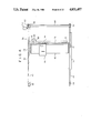
- FIG. 2 is a partially cutaway side view of the scanner printer in FIG. 1,
- FIG. 3 is a perspective view of the internal structure of the scanner printer in FIG. 1,
- FIG. 4 is a plan view showing a drive mechanism
- FIG. 5 is a longitudinal sectional front view showing a sensor unit
- FIG. 6 is a plan view of the sensor unit shown in FIG. 5,
- FIG. 7 is a longitudinal sectional side view of the sensor unit shown in FIG. 5,
- FIG. 8 is a plan view showing a scanning width
- FIG. 9 is a plan view for explaining a scanning order
- FIG. 10 is a perspective view of a printer
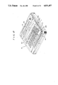
- FIG. 11 is a front view of a thermal head
- FIG. 12 is a side view of the thermal head in FIG. 11,
- FIG. 13 is a block diagram of a control circuit
- FIG. 14 is a flow chart of image formation
- FIGS. 15 and 16 show a modification of the first embodiment, in which FIG. 15 is a perspective view of a scanner printer, and FIG. 16 is a partially cutaway side view of the scanner printer shown in FIG. 15, and
- FIG. 17 is a perspective view of another modification of the first embodiment
- FIGS. 18 to 33 show a second embodiment of the present invention, in which:
- FIG. 18 is a perspective view of a scanner printer
- FIG. 19 is a plan view showing a coupling mechanism
- FIG. 20 is a perspective view showing a state wherein a main body is divided into a scanner unit and a printer unit,
- FIG. 21 is a perspective view showing a state wherein the main body is divided into the scanner unit and the printer unit, and they are connected through a coupling cord,
- FIG. 22 is a perspective view showing a printed circuit board housed in a document cover
- FIG. 23 is a side-sectional view of FIG. 22,
- FIG. 24 is a perspective view showing a state wherein a cassette is mounted on a main body
- FIG. 25 is a perspective view showing the cassette
- FIG. 26 is a sectional view showing a state wherein the cassette is mounted on the main body
- FIG. 27 is a perspective view of a modification of the second embodiment showing a state wherein a main body is divided into a scanner unit and a printer unit and they are stored in an attache case,
- FIGS. 28 to 33 show another modification of the second embodiment, in which:
- FIG. 28 is a perspective view showing a state wherein a television monitor and an additional unit are connected to the main body
- FIG. 29 is a perspective view showing the additional unit
- FIG. 30 is a perspective view showing a positioning guide
- FIG. 31 is a perspective view showing the relationship between the width of roll paper and the image formation width of the printer
- FIG. 32 is a block diagram of an interface circuit
- FIG. 33 is a flow chart of image formation
- FIGS. 34 to 43 show a third embodiment of the present invention, in which:
- FIG. 34 is a perspective view showing a state wherein a detachable unit is housed in a main body
- FIG. 35 is a plan view of the state shown in FIG. 34.
- FIG. 36 is a front view of the state shown in FIG. 34.
- FIG. 37 is a side view of the state shown in FIG. 34.
- FIG. 38 is a perspective view showing a state wherein the detachable unit is detached from the main body.
- FIGS. 39 to 43 show a modification of the third embodiment, in which:
- FIG. 39 is a perspective view showing a scanner printer
- FIG. 40 is a perspective view showing a scanner printer which opens a document cover
- FIG. 41 is a side view of the scanner printer
- FIG. 42 is a sectional view showing an internal arrangement
- FIG. 43 is an illustration showing the arrangement of the scanner.
- FIGS. 1 to 17 A first embodiment of the present invention will now be described with reference to FIGS. 1 to 17.
- reference numeral 2 denotes a main body of a serial scanner printer as an image forming apparatus according to the present invention.
- Document table (transparent glass) 4 is arranged on the upper surface portion of main body 2, and document cover 6 is arranged on table 4.
- the rear portion of document cover 6 is axially supported by shaft 8 to be freely opened or closed with respect to table 4.
- Keyboard unit 14 for operating scanner 10, printer 12, and the like is arranged on the upper surface portion of cover 6.
- Keyboard unit 14 comprises copy start key 16 for starting a copying operation, ten keys 18 for setting a copying number, display section 20 for displaying the copying number, density setting mode key 22, clear key 24 and the like, and is formed to be a flat panel. Since cover 6 is pivoted about shaft 8, keyboard unit 14 is connected to CPU 28 (to be described later) in main body 2 through flexible cable 26.
- Inlet port 30 and outlet port 32 for paper sheets (e.g., heat sensitive sheets) for printer 12 (to be described later) are formed in the upper rear surface of main body 2.
- Main body 2 includes scanner 10 for scanning an image formed on a document placed on table 4, and printer 12 for forming an image on a paper sheet in accordance with scanned data from scanner 10, as shown in FIG. 3.
- Scanner 10 is located below table 4, and printer 12 is located behind scanner 10.
- Scanner 10 comprises sensor unit 34 and drive mechanism 36.
- Sensor unit 34 senses document a placed on document table 4.
- Drive mechanism 36 reciprocates sensor unit 34 in the right-and-left direction (X direction) and the back-and-forth direction (Y direction).
- Drive mechanism 36 has guide rail 38 and guide shaft 40, as shown in FIG. 4.
- Guide rail 38 and guide shaft 40 are arranged to extend along the X direction.
- Guide rail 38 is arranged at the front side of scanner 10 in main body 2, and guide shaft 40 is arranged at the rear side thereof.
- First carriage 42 extends between guide rail 38 and guide shaft 40.
- First carriage 42 has roller 44 at its front side, and slider 46 at its rear side. Roller 44 is rotatable along guide rail 38, and slider 46 is slidably supported by guide shaft 40. Thereby, first carriage 42 is movable in the X direction.
- Timing belts 48 and 50 are coupled to the front and rear sides of first carriage 42, respectively.
- Timing belt 48 at the front side is looped between pulley 52 arranged near the right end of guide rail 38 and pulley 54 arranged near the left end thereof.
- Timing belt 50 at the rear side is looped between pulley 56 arranged near the right end of guide shaft 40 and pulley 58 arranged near the left end thereof.
- Pulleys 52 and 56 are mounted on the both ends of shaft 60.
- Shaft 60 is driven by first pulse motor 64 through reduction gears 62.
- First carriage 42 reciprocates along the X direction upon operation of first pulse motor 64.
- Second carriage 66 is supported by first carriage 42.
- Second carriage 66 has through hole 68 in its right portion, and recess portion 70 in its left portion, as shown in FIG. 5.
- Shaft 72 is slidably inserted in through hole 68, and is arranged on first carriage 42 along the Y direction.
- Recess portion 70 is slidably supported by the edge of first carriage 42.
- second carriage 66 is movable along the Y direction.
- Timing belt 74 is coupled to the right end portion of second carriage 66. Timing belt 74 is looped between a pair of pulleys 76 and 78 arranged on the front and rear sides of first carriage 42. Pulley 78 at the rear side is driven by second pulse motor 82 through reduction gears 80. Second carriage 66 reciprocates along the Y direction upon operation of second pulse motor 82.
- Sensor unit 34 is arranged in second carriage 66, and has lamp 84, mirror 86, lens 88, and image sensor 90.
- Lamp 84 illuminates document a, and light L reflected thereby is guided onto image sensor 90, sequentially, through mirror 86 and lens 88.
- reference numeral 92 denotes a focusing screw. When screw 92 is operated, lens 88 is moved along its optical axis.
- Reference numeral 84 denotes an amplifier circuit board for image sensor 90. Image sensor 90 is mounted directly on circuit board 94 in order to eliminate the influence of noise.
- Reference numeral 96 denotes a mirror support for supporting mirror 86; 98, a window through which light L propagating from lamp 84 toward document a passes; and 100, a window through which light L propagating from document a toward mirror 86 passes.
- Image sensor 90 is a plural-bit image sensor, and drive mechanism 36 moves first carriage 42 by a pitch shorter than a width corresponding to the number of bits of image sensor 90. Therefore, as shown in FIG. 8, a 1-line document image is scanned by plural-bit width l of image sensor 90.
- sensor unit 34 starts scanning from position A at the front left side, and scans an image while moving along the Y direction toward the rear side.
- unit 34 reaches position B at the rear side, it is then immediately returned to the front side.
- unit 34 is shifted to the right by 1-line scanning width l. This operation is repeated until unit 34 reaches position C at the rear right side.
- Printer 12 has platen 102 for supporting and conveying a paper sheet, as shown in FIG. 10.
- Platen 102 is driven by third pulse motor 106 through reduction gears 104 by a predetermined pitch.
- Thermal head 108 faces platen 102, and is moved by head moving mechanism 110 along the axial direction of platen 102.
- head moving mechanism 110 has shaft 112 parallel to platen 102, and slider 114 is slidably supported by shaft 112. Slider 114 is coupled to timing belt 116. Timing belt 116 is looped between a pair of pulleys 118 and 120 arranged near the both ends of shaft 112. Pulley 120 is driven by fourth pulse motor 124 through reduction gears 122. Thermal head 108 is mounted on slider 114. Thus, thermal head 108 is movable along the axial direction of platen 102 upon operation of fourth pulse motor 124. As shown in FIGS. 11 and 12, heating members 126 of thermal head 108 are aligned along a direction perpendicular to the axial direction of platen 102, i.e., along the rotating direction of platen 102.
- thermal head 108 follows the scanning operation of scanner 10, and is performed at the same speed as that of the scanning operation.
- a print width corresponds to scanning width l of scanner 10.
- a paper guide and a paper press roller are arranged near platen 102.
- Control circuit 128 denotes a control circuit of this apparatus.
- Control circuit 128 comprises CPU (Central Processing Unit) 28 for controlling the entire apparatus, amplifier 130 for amplifying the output from image sensor 90 and supplying it to CPU 28, driver 132 for driving pulse motors 64 and 82 in accordance with a signal from CPU 28, and print controller 134 for controlling thermal head 108 and pulse motors 106 and 124 in accordance with the signal from CPU 28.
- CPU 28 controls driver 132 in accordance with these signals, and driver 132 drives pulse motors 64 and 82 under the control of CPU 28 (ST2).
- image sensor 90 starts the document scanning operation (ST3).
- Image data output from image sensor 90 is supplied to CPU 28 through amplifier 130, and CPU 28 supplies this image data to print controller 134 (ST4).
- Print controller 134 drives pulse motors 106 and 124 and thermal head 108 in accordance with the image data from CPU 28, thereby forming an image corresponding to the image data (ST5). If image formation has not been performed a preset number of times, the flow returns to step ST2, and image formation is performed again. If the image formation has been performed the preset number of times, the operation is completed (ST6).
- keyboard unit 14 is arranged on the upper surface of document cover 6, a special space for keyboard unit 14 can be omitted. Therefore, a compact apparatus can be provided.
- FIGS. 15 and 16 show a modification of keyboard unit 14.
- keyboard unit 14 has a keyboard for a personal computer, which includes character keys 142, ten keys 144, function keys 146, and the like.
- this apparatus when this apparatus is connected to CRT display 148 and floppy disk device 150, it can serve as an input/output apparatus for a personal computer, in which keyboard unit 14, printer 12, and scanner 10 are integrally arranged. Therefore, since a keyboard for the personal computer need not be separately provided, the system can be compact.
- FIG. 17 shows another modification of keyboard unit 14.
- Keyboard unit 14 of this modification has keyboard 158 consisting of character keys 152, ten keys 154, function keys 156, and the like, and display section 160 for displaying data input through keyboard 158.
- the apparatus of the present invention can be used as a wordprocessor or a typewriter.
- operation panel 162 for inputting copy operation data is arranged on the upper front surface of main body 2.
- reference numeral 202 denotes a main body of a serial scanner printer as an image forming apparatus according to the present invention.
- Main body 202 comprises scanner unit 204 incorporating scanner 10, and printer unit 206 incorporating printer 12.
- Document table (transparent glass) 208 for placing a document thereon is arranged on the upper surface portion of scanner unit 204.
- Document cover 210 is arranged on document table 208.
- the rear portion of document cover 210 is axially supported by shaft 212 (FIG. 23) to be pivotable thereabout.
- Document cover 210 is openable and closeable with respect to document table 208.
- Operation panel 214 for performing a copying operation is arranged on the front upper surface of scanner unit 204.
- Inlet port 216 and outlet port 218 for paper sheets (e.g., heat sensitive sheets) for printer 12 are formed in the upper rear surface of printer unit 206.
- coupling mechanism 220 is coupled by coupling mechanism 220 to be separable from each other, as shown in FIGS. 19 and 20. More specifically, coupling mechanism 220 has mechanical coupling mechanisms 222 and electrical coupling mechanism 224. Mechanical coupling mechanisms 222 mechanically couple scanner unit 204 and printer unit 206, and have coupling pins 226 and reception members 228. Pins 226 project at the front side of printer unit 206, and have annular recesses 230 therearound. Reception members 228 are arranged at the rear side of scanner unit 206. Each reception member 228 comprises a spring member for elastically clamping the corresponding coupling pin 226, and has projection 232 at its distal end portion, which is engaged with recess 230 of coupling pin 226.
- Electrical coupling mechanism 224 electrically couples scanner unit 204 and printer unit 206, and has a pair of connectors 234 and 236.
- Connector 234 is arranged on the front side of printer unit 206
- connector 236 is arranged on the rear side of scanner unit 204.
- the coupling operation of mechanism 224 is performed simultaneously with that of mechanisms 222.
- FIG. 21 when connectors 234 and 236 are coupled by coupling cord 238, scanner unit 204 and printer unit 206 can be used in a separated state.
- Document cover 210 incorporates printed circuit board 240 for control circuit 128, as shown in FIGS. 22 and 23. Since document cover 210 is pivoted about shaft 212 as a fulcrum, control circuit 128 is connected to various devices in main body 202 through flexible cable 242.
- cassette 248 has cassette case 250, as shown in FIG. 25, and case 250 houses thermal transfer ribbon 252, supply roller 254 for supplying ribbon 252, takeup roller 256 for winding ribbon 252, drive motor 258 for driving roller 256, and power source (dry cells or battery) 260 for motor 258.
- Case 250 is provided with connecting terminal 262 and guide arm 264.
- Guide arm 264 has a shape which allows it to be fitted in groove 244, and guides ribbon 252 supplied from roller 254 and taken up by roller 256.
- ribbon 252 can be exposed midway along guide arm 264.
- cassette 248 is mounted on the outer rear portion of printer unit 206. In this state, ribbon 252 is interposed between platen 102 and thermal head 108, and rollers 254 and 256 of cassette 248 are located outside printer unit 206.
- connecting terminal 262 of cassette 248 is connected to connecting terminal 266 of main body 202.
- reference numeral 268 denotes a door which is opened or closed when power source 260 is exchanged.
- main body 202 can be separated into scanner unit 204 and printer unit 206, the arrangements of scanner unit 204 and printer unit 206 can be changed as desired. Therefore, installation margin of the apparatus increases, providing a compact apparatus. In addition, this apparatus can be easily connected to other OA (office automation) equipment, and can be easily installed.
- OA office automation
- printed circuit board 240 Since printed circuit board 240 is housed in document cover 210, the height of main body 202 can be reduced. In addition, since printed circuit board 240 has a uniform thickness, it can be easily housed in cover 210, resulting a compact arrangement.
- Image formation onto a heat sensitive sheet is performed by removing cassette 248 from main body 202, and image formation onto a regular paper sheet is performed by mounting cassette 248 outside main body 202. Therefore, the space for cassette 248 can be omitted from main body 202, and the size of the apparatus can be reduced. Since cassette 248 is mounted outside main body 202, a storage amount of ribbon 252 can be increased without changing the size of main body 202. Since motor 258 for driving ribbon 252, and power source 260 therefor, are housed in cassette 248, a driving force need not be transmitted from main body 202 to cassette 248. As a result, the drive mechanism of main body 202 can be simplified.
- FIG. 27 shows a modification of printer unit 206.
- the size of printer unit 206 in the right-and-left direction is the same as that of scanner unit 204 in the back-and-forth direction.
- units 204 and 206 can be easily stored in general-purpose attache case 270, resulting in convenience and portability.
- FIGS. 28 to 33 show another modification of printer unit 204.
- additional unit 282 can be mounted on printer unit 204, as shown in FIG. 28.
- Additional unit 282 is mounted on unit 204 when image data from television monitor 284 is to be printed.
- opening 286 is formed in additional unit 282, and is opened or closed by lid 288.
- a paper sheet e.g., heat sensitive sheet
- wound in the form of a roll i.e., roll sheet 290
- Additional unit 282 has circuit board 292, which constitutes interface circuit 294 for outputting a video signal from television monitor 284 to printer 12.
- Input terminal 296 of interface circuit 294 is arranged on the back surface of additional unit 282, and is connected to connecting cable 298 extending from television monitor 284.
- connecting cable 300 to be connected to printer 12 extends from additional unit 282.
- a pair of positioning guides 302 are arranged at the rear side of printer unit 204 to be pivotal in the direction indicated by arrows, as shown in FIG. 30, so that they can be housed in printer unit 204. As shown in FIG. 31, when additional unit 282 is set with reference to positioning guides 302, the print start position of printer 12 and the position of roll sheet 290 can be correctly aligned. When image data from television monitor 284 is printed out, since the resultant image is small in terms of resolution, width m of roll sheet 290 is smaller than image formation width n of printer 12.
- Interface circuit 294 has comparator 304, sync signal detector 306, CPU 308, and video memory 310, as shown in FIG. 32.
- Comparator 304 compares the video signal supplied from television monitor 284 with a reference level, and supplies the comparison result to CPU 308.
- Sync signal detector 306 separates horizontal and vertical sync signals from the video signal from television monitor 284, and supplies them to CPU 308.
- CPU 308 converts the analog signal from comparator 304 into a digital signal, and temporarily stores it in video memory 310 together with the signals from detector 306.
- CPU 308 reads out the data stored in video memory 310, and supplies it to printer 12. As shown in FIG.
- CPU 308 converts the analog signal from comparator 304 into the digital signal, and temporarily stores it in video memory 310 together with the sync signals from detector 306 (ST5).
- the storage data is read out by CPU 308 for each frame of television images, and is supplied to printer 12 (ST6).
- printer 12 an image is formed on roll sheet 290 based on the data signal supplied from CPU 308 (ST7).
- FIGS. 34 to 43 A third embodiment of the present invention will now be described with reference to FIGS. 34 to 43.
- reference numeral 402 denotes a main body of a serial scanner printer as an image forming apparatus according to the present invention.
- Document table (transparent glass) 404 is arranged on the upper surface portion of main body 402, and document cover 406 is arranged thereon.
- the rear portion of document cover 406 is axially supported by a supporting shaft (not shown) to be pivotal thereabout.
- Operation panel 408 for performing a copying operation is arranged on the upper front surface of main body 402.
- Main body 402 includes scanner 10 and printer 12. Note that since scanner 10 and printer 12 have the same arrangement as that of the first embodiment, the same reference numerals in this embodiment denote the same parts as in the first embodiment, and a detailed description thereof will be omitted.
- Inlet port 410 and outlet port 412 for paper sheets (e.g., heat sensitive sheets) for printer 12 are formed in the upper rear surface of main body 402.
- the moving area of first carriage 42 of scanner 10 provides a space when scanner 10 is not used, and this space can store detachable unit 414.
- Detachable unit 414 houses printed circuit board 416 constituting a control circuit, power source (dry cells or battery) 418, and the like.
- detachable unit 414 is stored in the moving area from the bottom portion of main body 402, and is held by moving slide lock 420 in the direction of arrows in FIG. 37.
- slide lock 420 is released, detachable unit 414 is removed from main body 402, and connector 422 of detachable unit 414 is connected to a connector (not shown) of main body 402.
- connector 422 is housed inside detachable unit 414 through opening 424 (FIG. 38).
- Reference numeral 426 denotes a lid for opening and closing opening 424.
- detachable unit 414 housing circuit board 416 and power source 418 is removed from main body 402 when scanner 10 is used and is housed in the moving area of scanner 10 when it is not used, available space can be effectively used, resulting in a compact apparatus and high portability.
- FIGS. 39 to 43 show a modification of the third embodiment.
- FIGS. 39 to 41 show a line scanner printer as an image forming apparatus according to the present invention.
- Reference numeral 502 denotes a main body of the apparatus.
- Document table 504 for placing document a thereon is arranged on the upper surface portion of main body 502, and is inclined downward toward an operator. More specifically, document table 504 is inclined downward through ⁇ degrees with respect to horizontal plane 506.
- Document cover 508 is arranged on document table 504. The rear portion of document cover 508 is axially supported by a supporting shaft (not shown) to be pivotal thereabout. Thus, document cover 508 is openable and closeable with respect to document table 504.
- Operation panel 510 for performing a copying operation is arranged on the front surface of main body 502.
- Inlet port 512 and outlet port 514 for paper sheets (e.g., heat sensitive sheets) for printer 516 are formed in the upper rear surface of main body 502.
- main body 502 houses scanner 518 for scanning an image formed on document a placed on document table 504, and printer 516 for forming an image on paper sheet p in accordance with the scanned data from scanner 518.
- Scanner 518 is arranged below document table 504, and printer 516 is arranged behind scanner 518.
- Scanner 518 has first and second units 520 and 522, as shown in FIGS. 42 and 43.
- First unit 520 has LED array 524 and first mirror 526
- second unit 522 has second and third mirrors 528 and 530.
- First and second units 520 and 522 are respectively supported by front guide rail 532 and rear guide rail 534 at their front and rear end portions, and are movable along the direction indicated by the arrow in FIG. 40 through a drive means (not shown).
- the height of rear guide rail 534 is larger than that of front guide rail 532, so that first and second units 520 and 522 are supported by guide rails 532 and 534 while they are inclined downward in a direction perpendicular to their moving direction, i.e., they are held to be parallel to document table 504.
- Engaging chips 536 extend from the rear end portions of first and second units 520 and 522, and are engaged with rear guide rail 534. Thereby, the movement of first and second units 520 and 522 caused by force component F of weight G toward the inclined lower end is restricted.
- casing 538 is arranged in one side portion of main body 502 to house lens 540, CCD 542, and the like.
- LED array 524 illuminates document a, and first and second units 520 and 522 are moved along guide rails 532 and 534, thereby scanning the overall surface of document a.
- first and second units 520 and 522 are moved along guide rails 532 and 534, thereby scanning the overall surface of document a.
- light reflected by document a is focused onto CCD 542 through lens 540, and the image formed on document a is thus read.
- second unit 522 is moved at a speed 1/2 that of first unit 520.
- detachable unit 544 storing a control circuit and a power source is housed, in the moving area of first and second units 520 and 522, in the same manner as in the third embodiment.
- Printer 516 comprises platen 546, for conveying and supporting paper sheet p, and thermal head 548 approaching and separating from platen 546.
- Thermal head 548 is heated in accordance with image scanning data from CCD 542, and forms an image on paper sheet p.
- first and second units 520 and 522 tend to swing in the back-and-forth direction during traveling.
- first and second units 520 and 522 are inclined downwardly toward the operator, and engaging chips 536 are engaged with guide rail 534 at their rear end portions.
- the backward swinging of first and second units 520 and 522 is restricted by the force of their weight, which causes them to move forward.
- the forward swinging of units 520 and 522 is restricted by engaging chips 536 engaged with guide rail 534. Therefore, the swinging of first and second units 520 and 522 in the back-and-forth direction can be reliably prevented, thus maintaining a high scanning precision.
- detachable unit 544 can be stored in the moving area of first and second units 520 and 522, a compact apparatus can be provided, just as in the above embodiments.
Abstract
An image forming apparatus has a document table for placing a document thereon on the upper surface thereof. A scanner and a printr are provided in the apparatus. The scanner scans an image formed on the document placed on the document table. The printer forms an image based on the scanned data from the scanner. A document cover for covering the document placed on the document table is arranged on the upper portion of the apparatus. A keyboard unit is arranged on the upper surface of the document cover. An operator inputs operation data to the scanner and the printer through the keyboard unit.
Description
The present invention relates to an image forming apparatus, e.g., a serial scanner printer.
In image forming apparatuses of this type, a document table is arranged on the upper surface of the apparatus, and a scanner and a printer are arranged inside the apparatus. A document placed on the document table is scanned by the scanner, and an image is formed by the printer in accordance with the scanned data.
In these apparatuses, a keyboard for operating the scanner and the printer is arranged in front of the document table and on the upper surface of the apparatus, thus requiring a special space therefor.
Since the scanner and the printer are arranged integrally, their positions cannot be changed, resulting in limited installation possibilities.
A power source for driving the scanner and the printer is housed in the bottom or rear portion of the apparatus, thus also requiring a special space therefor.
The above drawbacks interfere with any possible size reduction of the conventional apparatus.
It is an object of the present invention to provide a compact image forming apparatus.
According to one aspect of the invention, there is provided an image forming apparatus which comprises a document table for placing a document thereon, image scanning means for scanning an image formed on the document placed on said document table and outputting the scanned data, document cover means for covering the document placed on said document table, data input means, provided in said document cover means, for inputting predetermined data, and image forming means for forming an image on an image forming member in accordance with at least one of the input data from said data input means and the scanned data from said image scanning means.
According to the image forming apparatus of the present invention, since the data input means is arranged on the document cover means, a space for the data input means can be omitted, resulting in a compact apparatus.
According to another aspect of the invention, there is provided an image forming apparatus which comprises an image scanning unit having image scanning means for scanning an image formed on a document and outputting the scanned data, an image forming unit having image forming means for forming an image based on the scanned data from said image scanning means, and coupling means for mechanically and electrically coupling said image scanning unit and said image forming unit to be detachable from each other.
According to the image forming apparatus of the present invention, since the image scanning unit and the image forming unit can be separated, this increases the installation possibilities of the apparatus, and reduces the size of the apparatus.
According to a further aspect of the invention, there is provided an image forming apparatus which comprises a document table for placing a document thereon, image scanning means for scanning an image formed on the document placed on said document table and outputting the scanned data, said image scanning means consisting of imaging means for sensing the image formed on the document, moving means for moving said imaging means, and a moving area of said imaging means, image forming means for forming an image based on the scanned data from said image scanning means, and a power source for driving said image scanning means and said image forming means, said power source being housed within the moving area when said image scanning means is not used and being removed from the moving area to be used when said image scanning means is used.
According to the image forming apparatus of the present invention, since the power source is housed within the moving area of the imaging means, a special space for the power source is not needed, resulting in a compact apparatus.
FIGS. 1 to 17 show a first embodiment of the present invention, in which:
FIG. 1 is a perspective view of a scanner printer,
FIG. 2 is a partially cutaway side view of the scanner printer in FIG. 1,
FIG. 3 is a perspective view of the internal structure of the scanner printer in FIG. 1,
FIG. 4 is a plan view showing a drive mechanism,
FIG. 5 is a longitudinal sectional front view showing a sensor unit,
FIG. 6 is a plan view of the sensor unit shown in FIG. 5,
FIG. 7 is a longitudinal sectional side view of the sensor unit shown in FIG. 5,
FIG. 8 is a plan view showing a scanning width,
FIG. 9 is a plan view for explaining a scanning order,
FIG. 10 is a perspective view of a printer,
FIG. 11 is a front view of a thermal head,
FIG. 12 is a side view of the thermal head in FIG. 11,
FIG. 13 is a block diagram of a control circuit,
FIG. 14 is a flow chart of image formation,
FIGS. 15 and 16 show a modification of the first embodiment, in which FIG. 15 is a perspective view of a scanner printer, and FIG. 16 is a partially cutaway side view of the scanner printer shown in FIG. 15, and
FIG. 17 is a perspective view of another modification of the first embodiment;
FIGS. 18 to 33 show a second embodiment of the present invention, in which:
FIG. 18 is a perspective view of a scanner printer,
FIG. 19 is a plan view showing a coupling mechanism,
FIG. 20 is a perspective view showing a state wherein a main body is divided into a scanner unit and a printer unit,
FIG. 21 is a perspective view showing a state wherein the main body is divided into the scanner unit and the printer unit, and they are connected through a coupling cord,
FIG. 22 is a perspective view showing a printed circuit board housed in a document cover,
FIG. 23 is a side-sectional view of FIG. 22,
FIG. 24 is a perspective view showing a state wherein a cassette is mounted on a main body,
FIG. 25 is a perspective view showing the cassette,
FIG. 26 is a sectional view showing a state wherein the cassette is mounted on the main body,
FIG. 27 is a perspective view of a modification of the second embodiment showing a state wherein a main body is divided into a scanner unit and a printer unit and they are stored in an attache case,
FIGS. 28 to 33 show another modification of the second embodiment, in which:
FIG. 28 is a perspective view showing a state wherein a television monitor and an additional unit are connected to the main body,
FIG. 29 is a perspective view showing the additional unit,
FIG. 30 is a perspective view showing a positioning guide,
FIG. 31 is a perspective view showing the relationship between the width of roll paper and the image formation width of the printer,
FIG. 32 is a block diagram of an interface circuit, and
FIG. 33 is a flow chart of image formation; and
FIGS. 34 to 43 show a third embodiment of the present invention, in which:
FIG. 34 is a perspective view showing a state wherein a detachable unit is housed in a main body,
FIG. 35 is a plan view of the state shown in FIG. 34,
FIG. 36 is a front view of the state shown in FIG. 34,
FIG. 37 is a side view of the state shown in FIG. 34,
FIG. 38 is a perspective view showing a state wherein the detachable unit is detached from the main body, and
FIGS. 39 to 43 show a modification of the third embodiment, in which:
FIG. 39 is a perspective view showing a scanner printer,
FIG. 40 is a perspective view showing a scanner printer which opens a document cover,
FIG. 41 is a side view of the scanner printer,
FIG. 42 is a sectional view showing an internal arrangement, and
FIG. 43 is an illustration showing the arrangement of the scanner.
A first embodiment of the present invention will now be described with reference to FIGS. 1 to 17.
Referring to FIGS. 1 and 2, reference numeral 2 denotes a main body of a serial scanner printer as an image forming apparatus according to the present invention. Document table (transparent glass) 4 is arranged on the upper surface portion of main body 2, and document cover 6 is arranged on table 4. The rear portion of document cover 6 is axially supported by shaft 8 to be freely opened or closed with respect to table 4.
Timing belt 74 is coupled to the right end portion of second carriage 66. Timing belt 74 is looped between a pair of pulleys 76 and 78 arranged on the front and rear sides of first carriage 42. Pulley 78 at the rear side is driven by second pulse motor 82 through reduction gears 80. Second carriage 66 reciprocates along the Y direction upon operation of second pulse motor 82.
Sensor unit 34 is arranged in second carriage 66, and has lamp 84, mirror 86, lens 88, and image sensor 90. Light L emitted from lamp 84 illuminates document a, and light L reflected thereby is guided onto image sensor 90, sequentially, through mirror 86 and lens 88.
Note that reference numeral 92 denotes a focusing screw. When screw 92 is operated, lens 88 is moved along its optical axis. Reference numeral 84 denotes an amplifier circuit board for image sensor 90. Image sensor 90 is mounted directly on circuit board 94 in order to eliminate the influence of noise. Reference numeral 96 denotes a mirror support for supporting mirror 86; 98, a window through which light L propagating from lamp 84 toward document a passes; and 100, a window through which light L propagating from document a toward mirror 86 passes.
As shown in FIG. 9, sensor unit 34 starts scanning from position A at the front left side, and scans an image while moving along the Y direction toward the rear side. When unit 34 reaches position B at the rear side, it is then immediately returned to the front side. During this operation, unit 34 is shifted to the right by 1-line scanning width l. This operation is repeated until unit 34 reaches position C at the rear right side. Printer 12 has platen 102 for supporting and conveying a paper sheet, as shown in FIG. 10. Platen 102 is driven by third pulse motor 106 through reduction gears 104 by a predetermined pitch. Thermal head 108 faces platen 102, and is moved by head moving mechanism 110 along the axial direction of platen 102. More specifically, head moving mechanism 110 has shaft 112 parallel to platen 102, and slider 114 is slidably supported by shaft 112. Slider 114 is coupled to timing belt 116. Timing belt 116 is looped between a pair of pulleys 118 and 120 arranged near the both ends of shaft 112. Pulley 120 is driven by fourth pulse motor 124 through reduction gears 122. Thermal head 108 is mounted on slider 114. Thus, thermal head 108 is movable along the axial direction of platen 102 upon operation of fourth pulse motor 124. As shown in FIGS. 11 and 12, heating members 126 of thermal head 108 are aligned along a direction perpendicular to the axial direction of platen 102, i.e., along the rotating direction of platen 102.
The printing operation of thermal head 108 follows the scanning operation of scanner 10, and is performed at the same speed as that of the scanning operation. A print width corresponds to scanning width l of scanner 10. In addition, a paper guide and a paper press roller (neither are shown) are arranged near platen 102.
Referring to FIG. 13, reference numeral 128 denotes a control circuit of this apparatus. Control circuit 128 comprises CPU (Central Processing Unit) 28 for controlling the entire apparatus, amplifier 130 for amplifying the output from image sensor 90 and supplying it to CPU 28, driver 132 for driving pulse motors 64 and 82 in accordance with a signal from CPU 28, and print controller 134 for controlling thermal head 108 and pulse motors 106 and 124 in accordance with the signal from CPU 28. Referring to FIG. 14, when an operator depresses one or more of the ten keys 18 and copy start key 16, a copy number setting signal and a copy start signal are supplied to CPU 28 (ST1). CPU 28 controls driver 132 in accordance with these signals, and driver 132 drives pulse motors 64 and 82 under the control of CPU 28 (ST2). Next, image sensor 90 starts the document scanning operation (ST3). Image data output from image sensor 90 is supplied to CPU 28 through amplifier 130, and CPU 28 supplies this image data to print controller 134 (ST4). Print controller 134 drives pulse motors 106 and 124 and thermal head 108 in accordance with the image data from CPU 28, thereby forming an image corresponding to the image data (ST5). If image formation has not been performed a preset number of times, the flow returns to step ST2, and image formation is performed again. If the image formation has been performed the preset number of times, the operation is completed (ST6).
With the above arrangement, since keyboard unit 14 is arranged on the upper surface of document cover 6, a special space for keyboard unit 14 can be omitted. Therefore, a compact apparatus can be provided.
FIGS. 15 and 16 show a modification of keyboard unit 14. In this modification, keyboard unit 14 has a keyboard for a personal computer, which includes character keys 142, ten keys 144, function keys 146, and the like. With this arrangement, when this apparatus is connected to CRT display 148 and floppy disk device 150, it can serve as an input/output apparatus for a personal computer, in which keyboard unit 14, printer 12, and scanner 10 are integrally arranged. Therefore, since a keyboard for the personal computer need not be separately provided, the system can be compact.
FIG. 17 shows another modification of keyboard unit 14. Keyboard unit 14 of this modification has keyboard 158 consisting of character keys 152, ten keys 154, function keys 156, and the like, and display section 160 for displaying data input through keyboard 158. With this arrangement, the apparatus of the present invention can be used as a wordprocessor or a typewriter. Note that in this modification, operation panel 162 for inputting copy operation data is arranged on the upper front surface of main body 2.
Next, a second embodiment of the present invention will be described with reference to FIGS. 18 to 33.
Referring to FIG. 18, reference numeral 202 denotes a main body of a serial scanner printer as an image forming apparatus according to the present invention. Main body 202 comprises scanner unit 204 incorporating scanner 10, and printer unit 206 incorporating printer 12.
Document table (transparent glass) 208 for placing a document thereon is arranged on the upper surface portion of scanner unit 204. Document cover 210 is arranged on document table 208. The rear portion of document cover 210 is axially supported by shaft 212 (FIG. 23) to be pivotable thereabout. Document cover 210 is openable and closeable with respect to document table 208. Operation panel 214 for performing a copying operation is arranged on the front upper surface of scanner unit 204.
As shown in FIGS. 18 and 24, U-shaped cassette mounting groove 244, open to the upper and back surfaces of printer unit 206, is formed in printer unit 206. When an image is to be formed on a paper sheet such as a heat sensitive sheet, lid 246 is fitted in groove 244. When an image is to be formed on a regular paper sheet, lid 246 is removed, and cassette 248 is mounted. More specifically, cassette 248 has cassette case 250, as shown in FIG. 25, and case 250 houses thermal transfer ribbon 252, supply roller 254 for supplying ribbon 252, takeup roller 256 for winding ribbon 252, drive motor 258 for driving roller 256, and power source (dry cells or battery) 260 for motor 258.
With the above arrangement, since main body 202 can be separated into scanner unit 204 and printer unit 206, the arrangements of scanner unit 204 and printer unit 206 can be changed as desired. Therefore, installation margin of the apparatus increases, providing a compact apparatus. In addition, this apparatus can be easily connected to other OA (office automation) equipment, and can be easily installed.
Since printed circuit board 240 is housed in document cover 210, the height of main body 202 can be reduced. In addition, since printed circuit board 240 has a uniform thickness, it can be easily housed in cover 210, resulting a compact arrangement.
Image formation onto a heat sensitive sheet is performed by removing cassette 248 from main body 202, and image formation onto a regular paper sheet is performed by mounting cassette 248 outside main body 202. Therefore, the space for cassette 248 can be omitted from main body 202, and the size of the apparatus can be reduced. Since cassette 248 is mounted outside main body 202, a storage amount of ribbon 252 can be increased without changing the size of main body 202. Since motor 258 for driving ribbon 252, and power source 260 therefor, are housed in cassette 248, a driving force need not be transmitted from main body 202 to cassette 248. As a result, the drive mechanism of main body 202 can be simplified. Moveover, since electrical power need not be supplied from main body 202 to cassette 248, the capacity of the power source (not shown) of main body 202 can be reduced. FIG. 27 shows a modification of printer unit 206. In this modification, the size of printer unit 206 in the right-and-left direction is the same as that of scanner unit 204 in the back-and-forth direction. Thus, units 204 and 206 can be easily stored in general-purpose attache case 270, resulting in convenience and portability.
FIGS. 28 to 33 show another modification of printer unit 204. In this modification, additional unit 282 can be mounted on printer unit 204, as shown in FIG. 28. Additional unit 282 is mounted on unit 204 when image data from television monitor 284 is to be printed. As shown in FIGS. 28 and 29, opening 286 is formed in additional unit 282, and is opened or closed by lid 288. A paper sheet (e.g., heat sensitive sheet) wound in the form of a roll, i.e., roll sheet 290, is held in additional unit 282 to be supplied therefrom. Additional unit 282 has circuit board 292, which constitutes interface circuit 294 for outputting a video signal from television monitor 284 to printer 12. Input terminal 296 of interface circuit 294 is arranged on the back surface of additional unit 282, and is connected to connecting cable 298 extending from television monitor 284. In addition, connecting cable 300 to be connected to printer 12 extends from additional unit 282.
A pair of positioning guides 302 are arranged at the rear side of printer unit 204 to be pivotal in the direction indicated by arrows, as shown in FIG. 30, so that they can be housed in printer unit 204. As shown in FIG. 31, when additional unit 282 is set with reference to positioning guides 302, the print start position of printer 12 and the position of roll sheet 290 can be correctly aligned. When image data from television monitor 284 is printed out, since the resultant image is small in terms of resolution, width m of roll sheet 290 is smaller than image formation width n of printer 12.
With this modification, since roll sheet 290 corresponding to the image size of television monitor 284 is used, a cumbersome paper setting operation can be omitted. In addition, since interface circuit 294 and roll sheet 290 are provided in additional unit 282, this provides good appearance, easy handling, and a compact apparatus.
A third embodiment of the present invention will now be described with reference to FIGS. 34 to 43.
Referring to FIG. 34, reference numeral 402 denotes a main body of a serial scanner printer as an image forming apparatus according to the present invention. Document table (transparent glass) 404 is arranged on the upper surface portion of main body 402, and document cover 406 is arranged thereon. The rear portion of document cover 406 is axially supported by a supporting shaft (not shown) to be pivotal thereabout. Thus, document cover 406 is openable and closeable with respect to document table 404. Operation panel 408 for performing a copying operation is arranged on the upper front surface of main body 402.
As shown in FIGS. 34 to 37, the moving area of first carriage 42 of scanner 10 provides a space when scanner 10 is not used, and this space can store detachable unit 414. Detachable unit 414 houses printed circuit board 416 constituting a control circuit, power source (dry cells or battery) 418, and the like. When scanner 10 is not used, detachable unit 414 is stored in the moving area from the bottom portion of main body 402, and is held by moving slide lock 420 in the direction of arrows in FIG. 37. As shown in FIG. 38, when scanner 10 is to be used, slide lock 420 is released, detachable unit 414 is removed from main body 402, and connector 422 of detachable unit 414 is connected to a connector (not shown) of main body 402. Note that connector 422 is housed inside detachable unit 414 through opening 424 (FIG. 38). Reference numeral 426 denotes a lid for opening and closing opening 424.
With this arrangement, since detachable unit 414 housing circuit board 416 and power source 418 is removed from main body 402 when scanner 10 is used and is housed in the moving area of scanner 10 when it is not used, available space can be effectively used, resulting in a compact apparatus and high portability.
FIGS. 39 to 43 show a modification of the third embodiment.
FIGS. 39 to 41 show a line scanner printer as an image forming apparatus according to the present invention. Reference numeral 502 denotes a main body of the apparatus. Document table 504 for placing document a thereon is arranged on the upper surface portion of main body 502, and is inclined downward toward an operator. More specifically, document table 504 is inclined downward through θ degrees with respect to horizontal plane 506. Document cover 508 is arranged on document table 504. The rear portion of document cover 508 is axially supported by a supporting shaft (not shown) to be pivotal thereabout. Thus, document cover 508 is openable and closeable with respect to document table 504. Operation panel 510 for performing a copying operation is arranged on the front surface of main body 502. Inlet port 512 and outlet port 514 for paper sheets (e.g., heat sensitive sheets) for printer 516 are formed in the upper rear surface of main body 502.
As shown in FIG. 42, main body 502 houses scanner 518 for scanning an image formed on document a placed on document table 504, and printer 516 for forming an image on paper sheet p in accordance with the scanned data from scanner 518. Scanner 518 is arranged below document table 504, and printer 516 is arranged behind scanner 518.
When the image formed on document a is to be scanned, LED array 524 illuminates document a, and first and second units 520 and 522 are moved along guide rails 532 and 534, thereby scanning the overall surface of document a. During the scanning operation, light reflected by document a is focused onto CCD 542 through lens 540, and the image formed on document a is thus read. Note that in order to provide a constant optical path length between first mirror 526 and lens 540, second unit 522 is moved at a speed 1/2 that of first unit 520.
When scanner 518 is not used, detachable unit 544 storing a control circuit and a power source is housed, in the moving area of first and second units 520 and 522, in the same manner as in the third embodiment.
During the image scanning operation, first and second units 520 and 522 tend to swing in the back-and-forth direction during traveling. However, as described above, first and second units 520 and 522 are inclined downwardly toward the operator, and engaging chips 536 are engaged with guide rail 534 at their rear end portions. For this reason, the backward swinging of first and second units 520 and 522 is restricted by the force of their weight, which causes them to move forward. For the same reason, the forward swinging of units 520 and 522 is restricted by engaging chips 536 engaged with guide rail 534. Therefore, the swinging of first and second units 520 and 522 in the back-and-forth direction can be reliably prevented, thus maintaining a high scanning precision.
Note that in this modification, since detachable unit 544 can be stored in the moving area of first and second units 520 and 522, a compact apparatus can be provided, just as in the above embodiments.
Claims (18)
1. An image reading apparatus comprising:
a document table for placing a document thereon;
image scanning means for scanning an image formed on the document placed on said document table and outputting the scanned data; and
document cover means for covering the document placed on said document table;
data input means, provided in said document cover means, for inputting predetermined data.
2. The apparatus according to claim 1, wherein
said data input means has operation keys for inputting operation data for operating said image scanning means.
3. The apparatus according to claim 1, wherein
said image reading apparatus is connected to an external device for receiving, processing, and outputting data, said external device having display means for displaying the data, and storage means for storing the data and outputting the storage data; and
said data input means has a keyboard for inputting data to said external device.
4. The apparatus according to claim 1, wherein
said data input means has a keyboard for inputting data for creating a document, and display means for displaying the data input from said keyboard.
5. An image forming apparatus comprising:
an image scanning unit having image scanning means for scanning an image formed on a document and outputting the scanned data;
an image forming unit having image forming means for forming an image based on the scanned data from said image scanning means; and
coupling means for mechanically and electrically coupling said image scanning unit and said image forming unit to be detachable from each other.
6. The apparatus according to claim 5, wherein
said coupling means has a mechanical coupling mechanism for mechanically coupling said image scanning unit and said image forming unit, and an electrical coupling mechanism for electrically coupling said image scanning means of said image scanning unit and said image forming means of said image forming unit.
7. The apparatus according to claim 6, wherein
said mechanical coupling mechanism has a pin provided on said image scanning unit and a reception portion, provided on said image forming unit, for elastically clamping said pin; and
said electrical coupling mechanism has a pair of connectors provided on said image scanning unit and said image forming unit, said connectors being coupled synchronous with coupling of said mechanical coupling mechanism.
8. The apparatus according to claim 5, wherein
said image forming apparatus further comprises a flexible cable, said flexible cable electrically connecting said image scanning unit and said image forming unit while said image scanning unit and said image forming unit are separated from each other.
9. The apparatus according to claim 5, wherein
said image scanning unit has a document table for placing a document thereon, document cover means for covering the document, and a control circuit provided in said document cover means.
10. The apparatus according to claim 5, wherein
said image forming unit has a platen for conveying and supporting an image forming member, and an image forming head for forming an image on the image forming member supported by said platen; and
said image forming apparatus further comprises cassette means incorporating an ink ribbon, said cassette means being detachably mounted on said image forming unit, thereby interposing the ink ribbon between said image forming member supported by said platen and said image forming head.
11. The apparatus according to claim 10, wherein
said cassette means has convey means for conveying an ink ribbon between said image forming member supported by said platen and said image forming head.
12. The apparatus according to claim 11, wherein
said cassette means has a power source for driving said convey means.
13. The apparatus according to claim 10, wherein
said cassette means is mounted outside said image forming unit.
14. The apparatus according to claim 5, wherein
said image forming apparatus further comprises holding means for holding an image forming member wound in the form of a roll to be supplied therefrom, said holding means being detachably mounted outside said image forming unit, and said image forming member being supplied between said platen and said image forming head.
15. The apparatus according to claim 14, wherein
said image forming apparatus is connected to external video means, and
said holding means has an interface, said interface supplying a video signal from said external video means as an image forming signal to said image forming means.
16. The image forming apparatus comprising:
a document table for placing a document thereon;
image scanning means for scanning an image formed on the document placed on said document table and outputting the scanned data, said image scanning means consisting of imaging means for sensing the image formed on the document, moving means for moving said imaging means, and a moving area of said imaging means;
image forming means for forming an image based on the scanned data from said image scanning means; and
a power source for driving said image scanning means and said image forming means, said power source being housed within the moving area when said image scanning means is not used and being removed from the moving area to be used when said image scanning means is used.
17. The apparatus according to claim 16, wherein
said moving means has guide means for supporting said imaging means to be reciprocated, said guide means supporting said imaging means to be inclined in a direction perpendicular to a moving direction of said imaging means.
18. The apparatus according to claim 17, wherein
said guide means has a pair of parallel guide rails, which are separated from each other in a direction perpendicular to the moving direction of said imaging means, one of said guide rails being arranged at a level higher than the other, and
said imaging means has an engaging member at its inclined upper end side, the movement of said imaging means toward the inclined lower end thereof being restricted when said engaging member is engaged with one of said guide rails.
Applications Claiming Priority (14)
| Application Number | Priority Date | Filing Date | Title |
|---|---|---|---|
| JP60-155537 | 1985-07-15 | ||
| JP60-155539 | 1985-07-15 | ||
| JP60-155541 | 1985-07-15 | ||
| JP60-155538 | 1985-07-15 | ||
| JP60155538A JPS6216659A (en) | 1985-07-15 | 1985-07-15 | Image forming device |
| JP60155539A JPS6216660A (en) | 1985-07-15 | 1985-07-15 | Image forming device |
| JP60155533A JPS6216657A (en) | 1985-07-15 | 1985-07-15 | Image forming device |
| JP60-155533 | 1985-07-15 | ||
| JP15553485A JPS6216178A (en) | 1985-07-15 | 1985-07-15 | Image-forming device |
| JP60155541A JPS6216661A (en) | 1985-07-15 | 1985-07-15 | Image forming device |
| JP15553785A JPS6216179A (en) | 1985-07-15 | 1985-07-15 | Image-forming device |
| JP60-155534 | 1985-07-15 | ||
| JP60-162852 | 1985-07-25 | ||
| JP60162852A JPS6224765A (en) | 1985-07-25 | 1985-07-25 | Picture forming device |
Related Parent Applications (1)
| Application Number | Title | Priority Date | Filing Date |
|---|---|---|---|
| US06/883,722 Division US4731667A (en) | 1985-07-15 | 1986-07-09 | Image forming apparatus |
Publications (1)
| Publication Number | Publication Date |
|---|---|
| US4831457A true US4831457A (en) | 1989-05-16 |
Family
ID=27566179
Family Applications (2)
| Application Number | Title | Priority Date | Filing Date |
|---|---|---|---|
| US06/883,722 Expired - Lifetime US4731667A (en) | 1985-07-15 | 1986-07-09 | Image forming apparatus |
| US07/092,323 Expired - Lifetime US4831457A (en) | 1985-07-15 | 1987-09-02 | Image forming apparatus |
Family Applications Before (1)
| Application Number | Title | Priority Date | Filing Date |
|---|---|---|---|
| US06/883,722 Expired - Lifetime US4731667A (en) | 1985-07-15 | 1986-07-09 | Image forming apparatus |
Country Status (2)
| Country | Link |
|---|---|
| US (2) | US4731667A (en) |
| DE (1) | DE3623733A1 (en) |
Cited By (21)
| Publication number | Priority date | Publication date | Assignee | Title |
|---|---|---|---|---|
| US5033859A (en) * | 1988-10-17 | 1991-07-23 | Murata Kikai Kabushiki Kaisha | Facsimile apparatus |
| US5119212A (en) * | 1988-09-28 | 1992-06-02 | Kabushiki Kaisha Toshiba | Image reading apparatus |
| US5130817A (en) * | 1989-03-30 | 1992-07-14 | Sharp Kabushiki Kaisha | Electronic apparatus |
| US5477238A (en) * | 1992-02-13 | 1995-12-19 | Aharanson; Ophira R. | Method of and station for integrated typed data and optically scanned data capture for computer interfacing and the like |
| US5892523A (en) * | 1995-05-18 | 1999-04-06 | Canon Kabushiki Kaisha | Reading unit and printing apparatus capable of mounting such reading unit thereon |
| US6078407A (en) * | 1997-12-08 | 2000-06-20 | Ma; His Kuaeg | Portable computer and scanner arrangement |
| US6091516A (en) * | 1998-02-07 | 2000-07-18 | Umax Data Systems Inc. | Device for holding and moving a contact image sensor |
| US6166830A (en) * | 1998-07-01 | 2000-12-26 | Koh; Chong S. | Integrated scan-to-store apparatus |
| US20020036807A1 (en) * | 1996-11-05 | 2002-03-28 | Hitoshi Terashima | Apparatus eqipped with removable scanner unit |
| US20020149787A1 (en) * | 2001-04-17 | 2002-10-17 | Xerox Corporation | Sampling of customer images as color data for process control |
| US20030172795A1 (en) * | 2002-03-15 | 2003-09-18 | Lotfi Belkhir | Page turning apparatus with a vacuum plenum and an adaptive air fluffer |
| US6766126B2 (en) * | 2002-09-17 | 2004-07-20 | Silitek Corporation | Modified control panel used in office machine |
| DE102005009723A1 (en) * | 2005-03-03 | 2006-09-07 | Christine Slentidu | Laptop computer with integrated fax-capable scanner, has scanner at back of display and pivotable with lid via hinges, with operating pad provided at front of lid |
| US20070024925A1 (en) * | 2005-07-27 | 2007-02-01 | A Vision Inc. | Light-shielding device for a scanner and scanning method using the device |
| US20070234912A1 (en) * | 2003-04-17 | 2007-10-11 | Hiroshi Ishii | Image forming apparatus |
| USRE40435E1 (en) | 1993-03-23 | 2008-07-15 | Ricoh Company, Ltd. | Modular copying system using light wave, electric wave, or sonic wave interconnections |
| US20080252946A1 (en) * | 2007-04-16 | 2008-10-16 | Samsung Electronics Co., Ltd. | Image forming apparatus |
| US20080316551A1 (en) * | 2002-09-10 | 2008-12-25 | Kirtas Technologies, Inc. | Automated page turning apparatus to assist in viewing pages of a document |
| US7557965B2 (en) | 2002-09-10 | 2009-07-07 | Kirtas Technologies, Inc. | Automated page turning apparatus to assist in viewing pages of a document |
| US20090180085A1 (en) * | 2008-01-15 | 2009-07-16 | Kirtas Technologies, Inc. | System and method for large format imaging |
| DE202009000959U1 (en) * | 2009-01-26 | 2010-07-01 | Klouda, Jaroslav, Dipl.-Ing. | Portable computer with printing and / or scanning and / or copying device |
Families Citing this family (12)
| Publication number | Priority date | Publication date | Assignee | Title |
|---|---|---|---|---|
| US4893196A (en) * | 1987-04-09 | 1990-01-09 | Kabushiki Kaisha Toshiba | Image reading apparatus |
| US5047870A (en) * | 1988-03-17 | 1991-09-10 | Optum Corporation | Image reproduction system utilizing single operation scanning/reproducing |
| JP2763116B2 (en) * | 1988-10-31 | 1998-06-11 | 株式会社東芝 | Image forming device |
| US5327250A (en) * | 1989-03-31 | 1994-07-05 | Canon Kabushiki Kaisha | Facsimile device |
| JP3009897B2 (en) * | 1989-08-02 | 2000-02-14 | ヘッドスタート・テクノロジーズ・カンパニー ア ディビジョン オブ ノース・アメリカン・フィリップス・コーポレーション | Portable computer |
| WO1992003884A1 (en) * | 1990-08-14 | 1992-03-05 | Haber Alan P | A computer keyboard |
| US5375165A (en) * | 1990-08-14 | 1994-12-20 | Haber; Alan P. | Computer keyboard having both a standard keyboard mode and a telephone control mode |
| US5329377A (en) * | 1992-09-14 | 1994-07-12 | Ethix Corporation | Facsimile communicating aid |
| EP0768597B1 (en) * | 1995-10-13 | 2004-06-09 | Dov Aharanson | Integrated data capture devices for computers |
| US5822080A (en) * | 1996-09-04 | 1998-10-13 | Hewlett-Packard Company | Desktop space-saver scanner |
| JP2004347720A (en) * | 2003-05-20 | 2004-12-09 | Brother Ind Ltd | Image forming apparatus |
| JP7229782B2 (en) | 2019-01-09 | 2023-02-28 | キヤノン株式会社 | Measuring device and image forming system |
Citations (3)
| Publication number | Priority date | Publication date | Assignee | Title |
|---|---|---|---|---|
| US4449152A (en) * | 1980-12-10 | 1984-05-15 | Fuji Xerox Co., Ltd. | Copying machine |
| US4652937A (en) * | 1985-03-30 | 1987-03-24 | Kabushiki Kaisha Toshiba | Facsimile device |
| US4771336A (en) * | 1986-11-11 | 1988-09-13 | Dainippon Screen Mfg. Co., Ltd. | Device for setting trimming areas of an original |
Family Cites Families (4)
| Publication number | Priority date | Publication date | Assignee | Title |
|---|---|---|---|---|
| US4317137A (en) * | 1978-05-17 | 1982-02-23 | Harris Corporation | Optical scan head and printer |
| JPS55138967A (en) * | 1979-04-17 | 1980-10-30 | Fuji Xerox Co Ltd | Copying machine |
| DE3335657A1 (en) * | 1982-10-01 | 1984-04-05 | Canon K.K., Tokyo | IMAGE PROCESSING SYSTEM |
| JPS61113355A (en) * | 1984-11-07 | 1986-05-31 | Toshiba Corp | Picture forming device |
-
1986
- 1986-07-09 US US06/883,722 patent/US4731667A/en not_active Expired - Lifetime
- 1986-07-14 DE DE19863623733 patent/DE3623733A1/en active Granted
-
1987
- 1987-09-02 US US07/092,323 patent/US4831457A/en not_active Expired - Lifetime
Patent Citations (3)
| Publication number | Priority date | Publication date | Assignee | Title |
|---|---|---|---|---|
| US4449152A (en) * | 1980-12-10 | 1984-05-15 | Fuji Xerox Co., Ltd. | Copying machine |
| US4652937A (en) * | 1985-03-30 | 1987-03-24 | Kabushiki Kaisha Toshiba | Facsimile device |
| US4771336A (en) * | 1986-11-11 | 1988-09-13 | Dainippon Screen Mfg. Co., Ltd. | Device for setting trimming areas of an original |
Cited By (29)
| Publication number | Priority date | Publication date | Assignee | Title |
|---|---|---|---|---|
| US5119212A (en) * | 1988-09-28 | 1992-06-02 | Kabushiki Kaisha Toshiba | Image reading apparatus |
| US5033859A (en) * | 1988-10-17 | 1991-07-23 | Murata Kikai Kabushiki Kaisha | Facsimile apparatus |
| US5130817A (en) * | 1989-03-30 | 1992-07-14 | Sharp Kabushiki Kaisha | Electronic apparatus |
| US20070268257A1 (en) * | 1992-02-13 | 2007-11-22 | Aharanson Ophira R | Method of and station for integrated typed data and optically scanned data capture for computer interfacing and the like |
| US5477238A (en) * | 1992-02-13 | 1995-12-19 | Aharanson; Ophira R. | Method of and station for integrated typed data and optically scanned data capture for computer interfacing and the like |
| US5623285A (en) * | 1992-02-13 | 1997-04-22 | Aharonson; Ophira R. | Method of and station for integrated typed data and optically scanned data capture for computer interfacing and the like |
| USRE40435E1 (en) | 1993-03-23 | 2008-07-15 | Ricoh Company, Ltd. | Modular copying system using light wave, electric wave, or sonic wave interconnections |
| US5892523A (en) * | 1995-05-18 | 1999-04-06 | Canon Kabushiki Kaisha | Reading unit and printing apparatus capable of mounting such reading unit thereon |
| US20020036807A1 (en) * | 1996-11-05 | 2002-03-28 | Hitoshi Terashima | Apparatus eqipped with removable scanner unit |
| US6078407A (en) * | 1997-12-08 | 2000-06-20 | Ma; His Kuaeg | Portable computer and scanner arrangement |
| US6091516A (en) * | 1998-02-07 | 2000-07-18 | Umax Data Systems Inc. | Device for holding and moving a contact image sensor |
| US6166830A (en) * | 1998-07-01 | 2000-12-26 | Koh; Chong S. | Integrated scan-to-store apparatus |
| US20020149787A1 (en) * | 2001-04-17 | 2002-10-17 | Xerox Corporation | Sampling of customer images as color data for process control |
| US20030172795A1 (en) * | 2002-03-15 | 2003-09-18 | Lotfi Belkhir | Page turning apparatus with a vacuum plenum and an adaptive air fluffer |
| US7595915B2 (en) | 2002-03-15 | 2009-09-29 | Kirtas Technologies, Inc. | Page turning apparatus with a vacuum plenum and an adaptive air fluffer |
| US7557965B2 (en) | 2002-09-10 | 2009-07-07 | Kirtas Technologies, Inc. | Automated page turning apparatus to assist in viewing pages of a document |
| US20080316551A1 (en) * | 2002-09-10 | 2008-12-25 | Kirtas Technologies, Inc. | Automated page turning apparatus to assist in viewing pages of a document |
| US6766126B2 (en) * | 2002-09-17 | 2004-07-20 | Silitek Corporation | Modified control panel used in office machine |
| US20070234912A1 (en) * | 2003-04-17 | 2007-10-11 | Hiroshi Ishii | Image forming apparatus |
| US7620345B2 (en) * | 2003-04-17 | 2009-11-17 | Ricoh Company, Ltd. | Image forming apparatus including an operation panel provided on a facing |
| DE102005009723B4 (en) * | 2005-03-03 | 2007-04-05 | Christine Slentidu | Laptop with integrated, faxable scanner device |
| DE102005009723A1 (en) * | 2005-03-03 | 2006-09-07 | Christine Slentidu | Laptop computer with integrated fax-capable scanner, has scanner at back of display and pivotable with lid via hinges, with operating pad provided at front of lid |
| US20070024925A1 (en) * | 2005-07-27 | 2007-02-01 | A Vision Inc. | Light-shielding device for a scanner and scanning method using the device |
| US20080252946A1 (en) * | 2007-04-16 | 2008-10-16 | Samsung Electronics Co., Ltd. | Image forming apparatus |
| US8036569B2 (en) * | 2007-04-16 | 2011-10-11 | Samsung Electronics Co., Ltd. | Image forming apparatus having co-planer top cover and operation panel |
| US20150319321A1 (en) * | 2007-04-16 | 2015-11-05 | Samsung Electronics Co., Ltd. | Image forming apparatus having co-planar top cover and operation panel |
| WO2009091852A1 (en) * | 2008-01-15 | 2009-07-23 | Kirtas Technologies Inc. | System and method for large format imaging |
| US20090180085A1 (en) * | 2008-01-15 | 2009-07-16 | Kirtas Technologies, Inc. | System and method for large format imaging |
| DE202009000959U1 (en) * | 2009-01-26 | 2010-07-01 | Klouda, Jaroslav, Dipl.-Ing. | Portable computer with printing and / or scanning and / or copying device |
Also Published As
| Publication number | Publication date |
|---|---|
| US4731667A (en) | 1988-03-15 |
| DE3623733A1 (en) | 1987-02-05 |
| DE3623733C2 (en) | 1989-12-14 |
Similar Documents
| Publication | Publication Date | Title |
|---|---|---|
| US4831457A (en) | Image forming apparatus | |
| US4823195A (en) | Recording apparatus | |
| CA2044341C (en) | Compact read/write scanner | |
| US7426113B2 (en) | Electronic device | |
| US5621544A (en) | Image reading device and image information processing apparatus | |
| US4708486A (en) | Image-forming apparatus | |
| US4779141A (en) | Image forming apparatus | |
| JPS61105960A (en) | Information reading device | |
| US4777533A (en) | Image forming apparatus | |
| US4860029A (en) | Image information apparatus | |
| JPS62220056A (en) | Image forming device | |
| JP2007273663A (en) | Electronic apparatus | |
| JPS62200861A (en) | Image forming device | |
| JP3809834B2 (en) | Image reading device | |
| JPS62174167A (en) | Image forming device | |
| JP2547397B2 (en) | Information processing device | |
| JP2516910B2 (en) | Information processing device | |
| JP2022102390A (en) | Sheet conveying device | |
| JPS6216180A (en) | Image-forming device | |
| JPS613558A (en) | Information reader | |
| JPS62287768A (en) | Original reader | |
| JP2606282Y2 (en) | Facsimile machine | |
| JPS6150460A (en) | Information reader | |
| JPS62173852A (en) | Image forming device | |
| JPS61265956A (en) | Image forming device |
Legal Events
| Date | Code | Title | Description |
|---|---|---|---|
| STCF | Information on status: patent grant |
Free format text: PATENTED CASE |
|
| FEPP | Fee payment procedure |
Free format text: PAYOR NUMBER ASSIGNED (ORIGINAL EVENT CODE: ASPN); ENTITY STATUS OF PATENT OWNER: LARGE ENTITY |
|
| FPAY | Fee payment |
Year of fee payment: 4 |
|
| FPAY | Fee payment |
Year of fee payment: 8 |
|
| FPAY | Fee payment |
Year of fee payment: 12 |