US4838968A - Apparatus and method for making V-groove insulation - Google Patents
Apparatus and method for making V-groove insulation Download PDFInfo
- Publication number
- US4838968A US4838968A US07/119,821 US11982187A US4838968A US 4838968 A US4838968 A US 4838968A US 11982187 A US11982187 A US 11982187A US 4838968 A US4838968 A US 4838968A
- Authority
- US
- United States
- Prior art keywords
- length
- insulation
- lengths
- backing
- along
- Prior art date
- Legal status (The legal status is an assumption and is not a legal conclusion. Google has not performed a legal analysis and makes no representation as to the accuracy of the status listed.)
- Expired - Lifetime
Links
Images


Classifications
-
- B—PERFORMING OPERATIONS; TRANSPORTING
- B23—MACHINE TOOLS; METAL-WORKING NOT OTHERWISE PROVIDED FOR
- B23D—PLANING; SLOTTING; SHEARING; BROACHING; SAWING; FILING; SCRAPING; LIKE OPERATIONS FOR WORKING METAL BY REMOVING MATERIAL, NOT OTHERWISE PROVIDED FOR
- B23D45/00—Sawing machines or sawing devices with circular saw blades or with friction saw discs
- B23D45/14—Sawing machines or sawing devices with circular saw blades or with friction saw discs for cutting otherwise than in a plane perpendicular to the axis of the stock, e.g. for making a mitred cut
- B23D45/143—Sawing machines or sawing devices with circular saw blades or with friction saw discs for cutting otherwise than in a plane perpendicular to the axis of the stock, e.g. for making a mitred cut with a plurality of circular saw blades
- B23D45/146—Sawing machines or sawing devices with circular saw blades or with friction saw discs for cutting otherwise than in a plane perpendicular to the axis of the stock, e.g. for making a mitred cut with a plurality of circular saw blades the saw blades being angularly fixed
-
- B—PERFORMING OPERATIONS; TRANSPORTING
- B32—LAYERED PRODUCTS
- B32B—LAYERED PRODUCTS, i.e. PRODUCTS BUILT-UP OF STRATA OF FLAT OR NON-FLAT, e.g. CELLULAR OR HONEYCOMB, FORM
- B32B3/00—Layered products comprising a layer with external or internal discontinuities or unevennesses, or a layer of non-planar form; Layered products having particular features of form
- B32B3/26—Layered products comprising a layer with external or internal discontinuities or unevennesses, or a layer of non-planar form; Layered products having particular features of form characterised by a particular shape of the outline of the cross-section of a continuous layer; characterised by a layer with cavities or internal voids ; characterised by an apertured layer
- B32B3/30—Layered products comprising a layer with external or internal discontinuities or unevennesses, or a layer of non-planar form; Layered products having particular features of form characterised by a particular shape of the outline of the cross-section of a continuous layer; characterised by a layer with cavities or internal voids ; characterised by an apertured layer characterised by a layer formed with recesses or projections, e.g. hollows, grooves, protuberances, ribs
-
- B—PERFORMING OPERATIONS; TRANSPORTING
- B23—MACHINE TOOLS; METAL-WORKING NOT OTHERWISE PROVIDED FOR
- B23D—PLANING; SLOTTING; SHEARING; BROACHING; SAWING; FILING; SCRAPING; LIKE OPERATIONS FOR WORKING METAL BY REMOVING MATERIAL, NOT OTHERWISE PROVIDED FOR
- B23D53/00—Machines or devices for sawing with strap saw-blades which are effectively endless in use, e.g. for contour cutting
- B23D53/02—Machines or devices for sawing with strap saw-blades which are effectively endless in use, e.g. for contour cutting with stationarily-mounted wheels, i.e. during sawing carrying the strap
-
- B—PERFORMING OPERATIONS; TRANSPORTING
- B27—WORKING OR PRESERVING WOOD OR SIMILAR MATERIAL; NAILING OR STAPLING MACHINES IN GENERAL
- B27B—SAWS FOR WOOD OR SIMILAR MATERIAL; COMPONENTS OR ACCESSORIES THEREFOR
- B27B25/00—Feeding devices for timber in saw mills or sawing machines; Feeding devices for trees
- B27B25/02—Feeding devices for timber in saw mills or sawing machines; Feeding devices for trees with feed and pressure rollers
-
- B—PERFORMING OPERATIONS; TRANSPORTING
- B27—WORKING OR PRESERVING WOOD OR SIMILAR MATERIAL; NAILING OR STAPLING MACHINES IN GENERAL
- B27G—ACCESSORY MACHINES OR APPARATUS FOR WORKING WOOD OR SIMILAR MATERIALS; TOOLS FOR WORKING WOOD OR SIMILAR MATERIALS; SAFETY DEVICES FOR WOOD WORKING MACHINES OR TOOLS
- B27G5/00—Machines or devices for working mitre joints with even abutting ends
-
- B—PERFORMING OPERATIONS; TRANSPORTING
- B29—WORKING OF PLASTICS; WORKING OF SUBSTANCES IN A PLASTIC STATE IN GENERAL
- B29C—SHAPING OR JOINING OF PLASTICS; SHAPING OF MATERIAL IN A PLASTIC STATE, NOT OTHERWISE PROVIDED FOR; AFTER-TREATMENT OF THE SHAPED PRODUCTS, e.g. REPAIRING
- B29C53/00—Shaping by bending, folding, twisting, straightening or flattening; Apparatus therefor
- B29C53/02—Bending or folding
- B29C53/04—Bending or folding of plates or sheets
- B29C53/06—Forming folding lines by pressing or scoring
-
- B—PERFORMING OPERATIONS; TRANSPORTING
- B32—LAYERED PRODUCTS
- B32B—LAYERED PRODUCTS, i.e. PRODUCTS BUILT-UP OF STRATA OF FLAT OR NON-FLAT, e.g. CELLULAR OR HONEYCOMB, FORM
- B32B38/00—Ancillary operations in connection with laminating processes
- B32B38/0004—Cutting, tearing or severing, e.g. bursting; Cutter details
-
- B—PERFORMING OPERATIONS; TRANSPORTING
- B29—WORKING OF PLASTICS; WORKING OF SUBSTANCES IN A PLASTIC STATE IN GENERAL
- B29C—SHAPING OR JOINING OF PLASTICS; SHAPING OF MATERIAL IN A PLASTIC STATE, NOT OTHERWISE PROVIDED FOR; AFTER-TREATMENT OF THE SHAPED PRODUCTS, e.g. REPAIRING
- B29C37/00—Component parts, details, accessories or auxiliary operations, not covered by group B29C33/00 or B29C35/00
- B29C37/0053—Moulding articles characterised by the shape of the surface, e.g. ribs, high polish
- B29C37/0057—Moulding single grooves or ribs, e.g. tear lines
-
- B—PERFORMING OPERATIONS; TRANSPORTING
- B29—WORKING OF PLASTICS; WORKING OF SUBSTANCES IN A PLASTIC STATE IN GENERAL
- B29L—INDEXING SCHEME ASSOCIATED WITH SUBCLASS B29C, RELATING TO PARTICULAR ARTICLES
- B29L2009/00—Layered products
-
- B—PERFORMING OPERATIONS; TRANSPORTING
- B29—WORKING OF PLASTICS; WORKING OF SUBSTANCES IN A PLASTIC STATE IN GENERAL
- B29L—INDEXING SCHEME ASSOCIATED WITH SUBCLASS B29C, RELATING TO PARTICULAR ARTICLES
- B29L2023/00—Tubular articles
- B29L2023/22—Tubes or pipes, i.e. rigid
-
- B—PERFORMING OPERATIONS; TRANSPORTING
- B32—LAYERED PRODUCTS
- B32B—LAYERED PRODUCTS, i.e. PRODUCTS BUILT-UP OF STRATA OF FLAT OR NON-FLAT, e.g. CELLULAR OR HONEYCOMB, FORM
- B32B2307/00—Properties of the layers or laminate
- B32B2307/30—Properties of the layers or laminate having particular thermal properties
- B32B2307/304—Insulating
-
- Y—GENERAL TAGGING OF NEW TECHNOLOGICAL DEVELOPMENTS; GENERAL TAGGING OF CROSS-SECTIONAL TECHNOLOGIES SPANNING OVER SEVERAL SECTIONS OF THE IPC; TECHNICAL SUBJECTS COVERED BY FORMER USPC CROSS-REFERENCE ART COLLECTIONS [XRACs] AND DIGESTS
- Y10—TECHNICAL SUBJECTS COVERED BY FORMER USPC
- Y10T—TECHNICAL SUBJECTS COVERED BY FORMER US CLASSIFICATION
- Y10T156/00—Adhesive bonding and miscellaneous chemical manufacture
- Y10T156/10—Methods of surface bonding and/or assembly therefor
- Y10T156/1002—Methods of surface bonding and/or assembly therefor with permanent bending or reshaping or surface deformation of self sustaining lamina
- Y10T156/1039—Surface deformation only of sandwich or lamina [e.g., embossed panels]
- Y10T156/1041—Subsequent to lamination
-
- Y—GENERAL TAGGING OF NEW TECHNOLOGICAL DEVELOPMENTS; GENERAL TAGGING OF CROSS-SECTIONAL TECHNOLOGIES SPANNING OVER SEVERAL SECTIONS OF THE IPC; TECHNICAL SUBJECTS COVERED BY FORMER USPC CROSS-REFERENCE ART COLLECTIONS [XRACs] AND DIGESTS
- Y10—TECHNICAL SUBJECTS COVERED BY FORMER USPC
- Y10T—TECHNICAL SUBJECTS COVERED BY FORMER US CLASSIFICATION
- Y10T156/00—Adhesive bonding and miscellaneous chemical manufacture
- Y10T156/10—Methods of surface bonding and/or assembly therefor
- Y10T156/1052—Methods of surface bonding and/or assembly therefor with cutting, punching, tearing or severing
- Y10T156/1082—Partial cutting bonded sandwich [e.g., grooving or incising]
-
- Y—GENERAL TAGGING OF NEW TECHNOLOGICAL DEVELOPMENTS; GENERAL TAGGING OF CROSS-SECTIONAL TECHNOLOGIES SPANNING OVER SEVERAL SECTIONS OF THE IPC; TECHNICAL SUBJECTS COVERED BY FORMER USPC CROSS-REFERENCE ART COLLECTIONS [XRACs] AND DIGESTS
- Y10—TECHNICAL SUBJECTS COVERED BY FORMER USPC
- Y10T—TECHNICAL SUBJECTS COVERED BY FORMER US CLASSIFICATION
- Y10T156/00—Adhesive bonding and miscellaneous chemical manufacture
- Y10T156/12—Surface bonding means and/or assembly means with cutting, punching, piercing, severing or tearing
- Y10T156/1317—Means feeding plural workpieces to be joined
-
- Y—GENERAL TAGGING OF NEW TECHNOLOGICAL DEVELOPMENTS; GENERAL TAGGING OF CROSS-SECTIONAL TECHNOLOGIES SPANNING OVER SEVERAL SECTIONS OF THE IPC; TECHNICAL SUBJECTS COVERED BY FORMER USPC CROSS-REFERENCE ART COLLECTIONS [XRACs] AND DIGESTS
- Y10—TECHNICAL SUBJECTS COVERED BY FORMER USPC
- Y10T—TECHNICAL SUBJECTS COVERED BY FORMER US CLASSIFICATION
- Y10T156/00—Adhesive bonding and miscellaneous chemical manufacture
- Y10T156/12—Surface bonding means and/or assembly means with cutting, punching, piercing, severing or tearing
- Y10T156/1348—Work traversing type
- Y10T156/1352—Work traversing type with liquid applying means
- Y10T156/1361—Cutting after bonding
-
- Y—GENERAL TAGGING OF NEW TECHNOLOGICAL DEVELOPMENTS; GENERAL TAGGING OF CROSS-SECTIONAL TECHNOLOGIES SPANNING OVER SEVERAL SECTIONS OF THE IPC; TECHNICAL SUBJECTS COVERED BY FORMER USPC CROSS-REFERENCE ART COLLECTIONS [XRACs] AND DIGESTS
- Y10—TECHNICAL SUBJECTS COVERED BY FORMER USPC
- Y10T—TECHNICAL SUBJECTS COVERED BY FORMER US CLASSIFICATION
- Y10T156/00—Adhesive bonding and miscellaneous chemical manufacture
- Y10T156/17—Surface bonding means and/or assemblymeans with work feeding or handling means
- Y10T156/1788—Work traversing type and/or means applying work to wall or static structure
- Y10T156/179—Work traversing type and/or means applying work to wall or static structure with liquid applying means
-
- Y—GENERAL TAGGING OF NEW TECHNOLOGICAL DEVELOPMENTS; GENERAL TAGGING OF CROSS-SECTIONAL TECHNOLOGIES SPANNING OVER SEVERAL SECTIONS OF THE IPC; TECHNICAL SUBJECTS COVERED BY FORMER USPC CROSS-REFERENCE ART COLLECTIONS [XRACs] AND DIGESTS
- Y10—TECHNICAL SUBJECTS COVERED BY FORMER USPC
- Y10T—TECHNICAL SUBJECTS COVERED BY FORMER US CLASSIFICATION
- Y10T428/00—Stock material or miscellaneous articles
- Y10T428/24—Structurally defined web or sheet [e.g., overall dimension, etc.]
- Y10T428/24479—Structurally defined web or sheet [e.g., overall dimension, etc.] including variation in thickness
- Y10T428/2457—Parallel ribs and/or grooves
-
- Y—GENERAL TAGGING OF NEW TECHNOLOGICAL DEVELOPMENTS; GENERAL TAGGING OF CROSS-SECTIONAL TECHNOLOGIES SPANNING OVER SEVERAL SECTIONS OF THE IPC; TECHNICAL SUBJECTS COVERED BY FORMER USPC CROSS-REFERENCE ART COLLECTIONS [XRACs] AND DIGESTS
- Y10—TECHNICAL SUBJECTS COVERED BY FORMER USPC
- Y10T—TECHNICAL SUBJECTS COVERED BY FORMER US CLASSIFICATION
- Y10T83/00—Cutting
- Y10T83/343—With means to deform work temporarily
Definitions
- the present invention relates generally to a method and apparatus for making V-groove insulation. More particularly, the present invention relates to an endless track fabrication and cutting system whereby prefabricated, sectional lengths of an insulation material are formed into continuous, grooved insulation sheets of variable dimensions.
- preformed insulation techniques include the overall cost to individually form or mold a given insulation section to its intended application around the thermal member. For a given length and diameter pipe or duct, a specific dimension insulating section must be formed, this process often time and energy intensive. Preformed insulation sections are also expensive from the standpoint of both storage and shipment. Further, preformed sections are not easily adapted to other applications and often poorly fit their original, intended application due to manufacturing tolerances.
- the present invention addresses the above noted and other disadvantages by providing a rapid, efficient, yet inexpensive method and apparatus for forming variable dimension sections of V-groove insulation adapted to form a compression fit around a given thermal member.
- prefabricated, sectional lengths of insulation material are placed end to end on an endless track conveyer system.
- the thickness of these lengths is then modified or "planed" commensurate with the particular insulation requirements for a given commission. This is preferably achieved by a band saw assembly disposed laterally across the conveyor track.
- a quick drying contact adhesive is evenly applied to the upper side of the insulation section. This adhesive secures a continuous length of a backing material to the sections.
- This backing material securely, yet flexibly holds the insulation sections in their abutted end-to-end relationship so as to form a continuous integral sheet.
- This integral sheet is then passed over a cutting and grooving assembly situated below the conveyer system, where a series of grooves or notches are formed in its lower surface. At the completion of the grooving process, the integral sheet may be cut into prescribed lengths.
- the above described process is preferably controlled via a microprocessor assembly.
- the various and individual steps of planing, gluing, cutting, etc. are preferably coordinated so as to produce a constant flow of prescription length V-groove insulation material at the terminal, output end of the system.
- the present invention includes the design of the V-groove cutting assembly.
- the cutting assembly includes hydraulic circular saw assemblies positioned along a relatively movable accurate track in an offset relationship. In such a fashion, the grooving saws may be accurately positioned and adjusted to provide the angle or depth of the groove desired in the finished insulation product.
- the present invention offers a number of advantages over the prior art.
- One such advantage is the ability of the present invention to economically produce selected quantities of a prescription-sized V-grooved insulation, where the final insulation product is characterized by a series of consistently clean cut grooves or notches.
- the present invention also offers the ability to quickly and precisely adjust the angle and depth at which a V-groove is cut in an insulation sheet, such that the final insulation product will maintain a precision compression fit over the pipe or duct to be insulated.
- the present invention provides a continuous fabrication and cutting process without a heavy generation of insulation dust.
- Yet another advantage of the present invention is the ability to closely control, regulate and modify the angulation and depth of V-grooves cut in the insulation sections, in addition to precisely controlling the spacing of these grooves.
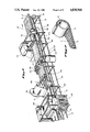
- FIG. 1 is a perspective view of a preferred embodiment of the present invention.
- FIG. 2 is a perspective view of the finished end product of the present invention as it may be wrapped around a thermal member.
- FIG. 3 is a side view of an aggregate insulation piece illustrating a V-cut groove or notch.
- FIG. 4 is a perspective view of the planing means.
- FIG. 5 is a side view of the planing means.
- FIG. 6A is a perspective cut-away view of the spraying or gluing system.
- FIG. 6B is a detailed perspective view of the spraying system illustrating a spray nozzle.
- FIG. 7A is a side view of the backing means as it may be situated relative to the conveyor track.
- FIG. 8 is a side cut-away view of the cutting and grooving means.
- the present invention is preferably comprised of a number of specialized assemblies or "stations", each disposed along, above or proximate to an endless track conveyor system.
- the conveyorsystem itself is generally comprised of an upright tubular frame 20 along the top of which are secured a plurality of rollers 22 or the like to form a bed 27. Flexibly disposed over these rollers 22 is a conventional looped belt arrangement (not shown) driven by a motor through guide rollers 23 such that the material placed atop the system may be moved longitudinally down the frame 20 for further processing as shown by direction arrow A.
- the travel rate of the conveyor system is governed by a microprocessor system, which, as will be later described, also governs the placement and frequency with which V-grooves are cut in a given insulation section 10.
- the planing means 100 is preferably comprised of a housing 114 situated above and connected to the frame 20.
- a band saw assembly 102 is laterally disposed in the housing 114 at a variable height above the frame bed 27 such that the saw blade 104 contacts the leading edge of a given insulation section 10 as it moves downstream.
- This blade 104 is preferably disposed at a uniform height along its length above the bed 27 such as to establish a uniform and prescribed thickness in the section 10.
- the planing or cutting operation of assembly 100 is carried out while insulation sections 10 move downstream toward the next station.
- the planing means 100 utilizes a conventional band saw having 20" diameter drive wheels 117 around which is secured a 6 pitch 3/4" precision blade 114.
- Drive wheels 117 are driven by a 2 horsepower 220 single phase electric motor (not shown) such that the blade 114 achieves an average operation speed of 1720 RPM.
- Tension in blade 114 may be modified via handwheel 106.
- the vertical position of the saw blade 104 relative the bed 27 may be varied by manual movement of adjustment wheel 135.
- Wheel 135 is connected to height adjustment chain 108, such that movement of wheel 135 causes chain 108 to move in a longitudinal fashion about sprockets 109, which in turn are connected to adjustment supports 112 secured to frame 20.
- Supports 112 in turn, threadedly engage housing supports 115 via a pinion or linear gear arrangement such that rotation of sprockets 109 results in a vertical movement of supports 115 relative to the frame 20.
- the housing 114 may be uniformly raised or lowered relative to the bed 27 so as to establish a desired thickness 130 in an insulation section 10 having a manufactured thickness 131.
- the planing assembly 110 is provided with an exhaust or vacuum system to remove dust and small insulation particulates generated as a result of the planing process.
- This system generally includes a conventional exhaust and ventilation system situated inside the housing 114 and operative via vacuum line 122. Due to the construction of housing 114, and the minimal agitation action of saw assembly 102, dust and particle generation are both minimized and contained with any generation being removed to an external collection bin or reservoir (not shown).
- a material removal system 150 may also be attached to the housing 114 downstream from the saw assembly 102 itself such that the upper, undesired portion of insulation material planed from the main insulation section 10 may be removed for disposal via a conveyor or other means. This removal system is powered by electric motor 104.
- the spraying assembly 200 is generally comprised of one or more upright supports 260 attached to the frame 20, said supports 260 slidably coupled to a support arm 240 via guide sleeves 261. As seen in FIG. 6A, in some embodiments one of these supports 260 may be replaced with a vertical adjustment assembly comprised of an upper member 243 disposed in a movable telescoping arrangement with lower member 225.
- a series of spray nozzle assemblies 220 such as a Bink's series 2001 spray gun assembly, are fixedly secured to the support arm 240 such that adhesive material discharged through the nozzles may be evenly applied over an insulation section 10.
- one or more connectors 242 connect the nozzle array 220 with a pressurized adhesive reservoir 210. (See. FIG. 1)
- a hydraulic connector line 223 is disposed through the support arm 240 in a looped arrangement to act as a heat source to prevent adhesive introduced into arm 240 from becoming too viscous during cold operation.
- nozzles 220 Also attached to nozzles 220 are a series of air connectors 221 and 222. Connector 221 is linked directly to nozzle 220 to provide an air flow onto the work surface through apertures 227 arranged at the periphery of nozzle tip 226. Liquid adhesive is pumped through the inner part of this nozzle tip 226, such that the combination air and adhesive flow results in a fan shaped propagation of adhesive over insulation section 10.
- Connector 222 is used to provide a source of air gun to activate nozzle 220 during forward movement of the insulation section 10 upon an electric signal from the microprocessor. This electric signal is used to open a solenoid valve which then allows air pressure to trigger the spraying action of the nozzle 220. Solenoids and their related controls are contained in housing 250.
- the exact distribution and concentration of the adhesive may be varied by altering the height of the support arm 240 and hence the nozzles 220 relative to the surface of the insulation section 10. This variable height may be adjusted by movement of handle 230 which operates as a screw jack to move upper member 243 vertically relative lower member 225.
- the backing means 300 preferably includes a support frame 386 rigidly secured to and suspended above the frame 20. Slidably secured to the frame 386 about tracks 384 is a spool support structure 390 adapted to rotatably accommodate a spool 310 of a backing material 11. Rotatably attached at the rear, downstream extent of the support frame 386 is a first guide roller 312 which is of a size sufficient to accommodate backing 11 of variable widths. Hinged at the frontal extent of the support frame 386 is an application roller arm 380 which accommodates an application roller 314.
- a pneumatic inducer 307 is disposed between support frame 386 and spool support structure 390.
- Inducer 307 is connected to an air supply via connector 309, and also to an electric eye guide means 360.
- spool support structure 390 may be urged in a lateral direction along rails 384.
- the application roller arm 380 contacts the moving insulation material 10 through roller 314 at a pressure determined by pneumatic cylinder 370. This pressure may be modified by increasing or decreasing the air supply to said cylinder 370 by a valve (not shown).
- the backing material 11 is paid off of the spool 310 where it is tensioned between rollers 312 and 314 and it then engages the prepared surface of the insulation section 10. In this fashion, a continuous length of backing material 11 is applied over the abutting sections 10 so as to form a continuous, integral sheet 12.
- the backing material 11 be exactly juxtaposed over the insulation material 10 before contact between the two surfaces is made. Due to inherent irregularities associated with different factory winding processes, however, not all backing materials will perform similarly in tensioned application, thus creating a series of wrinkles which may result in less than satisfactory adhesion of material 11 to insulation 10. Similarly, some backing materials may arrive from the factory “staggered” or unevenly wound on the roll. Due to these and other problems, therefore, an alignment apparatus is thus needed to ensure even distribution and alignment of the backing 11 on the insulation sheets 10.
- this alignment is preferably accomplished electronically via an electric eye guide means 360 such as a model No. 57044H/H1116 electric eye and control component as available from Hydralign, Inc.
- an electric eye guide means 360 such as a model No. 57044H/H1116 electric eye and control component as available from Hydralign, Inc.
- the electric eye assembly 360 is situated on the upper portion of the application roller arm 380 such as to contact the edge of backing material 11 tensioned between rollers 312 and 314.
- the electric eye and receptor 361 itself is disposed within the inner extent of a U-shaped housing 362 such that backing 11 tensioned between rollers 312 and 314 passes through the housing 362.
- the eye and receptor unit 361 is electrically coupled to inducer 307 thus resulting in a transverse adjustment of the spool frame 390 about tracks 384 so that precise alignment and fixation of the backing 11 to sections 10 may be automatically accomplished.
- the backing material 11 itself is preferably comprised of a flexible MylarTM or KevlarTM composition such as a Hypolon® TGH-100 laminate made by Alpha Associates, Inc. of Woodridge, N.J. or a foil scrim (FSK) or all service jacket (ASJ) as manufactured by LAMTEC Corp. of Flanders, N.J.
- a flexible MylarTM or KevlarTM composition such as a Hypolon® TGH-100 laminate made by Alpha Associates, Inc. of Woodridge, N.J. or a foil scrim (FSK) or all service jacket (ASJ) as manufactured by LAMTEC Corp. of Flanders, N.J.
- This assembly 400 is preferably comprised of two independent saw carriages slidably disposed beneath the bed 27 such that a variety of differently configured V-grooves may be quickly and precisely produced in the underside of the integral sheet 12.
- two hydraulic circular saws 450 are fixedly positioned on arcuate tracks 430 in an offset relationship as shown.
- the combination circular saw 450 and track 430 forms a carriage which is transversely movable relative to the integral insulation sheet 12 by drive wheels 460 engaging drive chains (not shown).
- These drive wheels 460 are mounted on a drive shaft 461 which in turn translates the movement of a drive motor (not shown) to accomplish transverse movement of the carriage about the bed 27.
- Each saw carriage is transversely movable to an extent beyond the lateral perimeter of the frame 20 such as to allow the insulation sheet 12 to progress after a given groove 13 is cut.
- the actuation of drive shaft 461 and hence the transverse movement of the saw carriages is governed by a microprocessor assembly (not shown).
- both sides of a V-groove or notch 13 may be cut as the carriage moves transverse to the long axis of the frame 20.
- V-grooves of the insulation material cut from the underside of the sheet 12 fall downwardly into a collection area of assembly 400 where they are removed to a continuous belt conveyor which transports them to a vacuum removal system (not shown).
- the design of the grooving apparatus 400 allows a variety of different depth and angulation V-grooves to be created in a given integral insulation section 12. This versatility is essential since for each diameter thermal member 15, a different aspect insulation piece must be generated.
- the frequency at which the grooves are formed in the underside of the integral sheet 12 is precisely controlled via a programmable microprocessor assembly (not shown). This assembly, is in turn, linked to the main drive motor of the conveyor system such as to regulate the rate at which the sheet of integral material 12 contacts cutting elements 452 of assembly 400.
- the angulation of the V-groove 13 may be quickly modified by adjustment of the relative posture of arcuate tracks 430 on which are affixed saw assemblies 450.
- the operator manually rotates handle 410 which results in a relative and equal movement between each frame 430, such that each saw assembly 450 is inclined to an equal and measurable degree so as to result in the formation of an isosceles V-grooved being formed in the underside of the integral sheet 12.
- the insulation sheet 10 will normally be of a greater thickness. Ordinarily in such applications, a commensurate increase in V-groove depth will also be needed. This increased depth may be achieved by vertical adjustment of the subassembly 405 relative frame 20 and hence bed 27. This is accomplished by rotation of height adjustment handle which engages chain 402 and sprocket 403. As noted, subframe 405 threadedly engages gearbox 409 secured to frame 20, by a pinion or linear gear 404. Thus coupled, rotation of adjustment handle 480 results in a vertical movement of the subframe 430 relative the frame 2, thus varying the penetration of the saw blades 452 into the bottomside of the sheet 12.
- the cutting and grooving operation 400 is also adapted to sever the integral sheet 12 into desired lengths commensurate with the given application. These lengths may be programmed into the microprocessor for automatic operation.
- saw assembly 450 is itself comprised of three component parts.
- the motor 461 is secured to a subframe 463 which itself is hingedly secured to a main frame 463, which as noted, is secured to track 430.
- a hydraulic cylinder 456 Disposed inside of main frame 463 is a hydraulic cylinder 456 which is electrically connected to the microprocessor.
- This cylinder 466 is oriented for operation in a plane almost normal to the bed 27. When actuated, cylinder 466 moves upward against subframe 463 which pivots about hinge 469 moving saw motor 451 and accompanying blade 452 upward as to result in a complete severance of the sheet 12. Upon completion, cylinder 466 returns to its original position.
Abstract
Description
Claims (22)
Priority Applications (4)
| Application Number | Priority Date | Filing Date | Title |
|---|---|---|---|
| US07/119,821 US4838968A (en) | 1987-11-12 | 1987-11-12 | Apparatus and method for making V-groove insulation |
| AU21938/88A AU625635B2 (en) | 1987-11-12 | 1988-09-07 | Apparatus and method for making v-groove insulation |
| US07/364,452 US4954202A (en) | 1987-11-12 | 1989-06-12 | Apparatus for making V-groove insulation |
| AU14868/92A AU1486892A (en) | 1987-11-12 | 1992-04-13 | Apparatus and method for making v-groove insulation |
Applications Claiming Priority (1)
| Application Number | Priority Date | Filing Date | Title |
|---|---|---|---|
| US07/119,821 US4838968A (en) | 1987-11-12 | 1987-11-12 | Apparatus and method for making V-groove insulation |
Related Child Applications (1)
| Application Number | Title | Priority Date | Filing Date |
|---|---|---|---|
| US07/364,452 Continuation-In-Part US4954202A (en) | 1987-11-12 | 1989-06-12 | Apparatus for making V-groove insulation |
Publications (1)
| Publication Number | Publication Date |
|---|---|
| US4838968A true US4838968A (en) | 1989-06-13 |
Family
ID=22386600
Family Applications (1)
| Application Number | Title | Priority Date | Filing Date |
|---|---|---|---|
| US07/119,821 Expired - Lifetime US4838968A (en) | 1987-11-12 | 1987-11-12 | Apparatus and method for making V-groove insulation |
Country Status (2)
| Country | Link |
|---|---|
| US (1) | US4838968A (en) |
| AU (2) | AU625635B2 (en) |
Cited By (21)
| Publication number | Priority date | Publication date | Assignee | Title |
|---|---|---|---|---|
| FR2648073A1 (en) * | 1989-06-12 | 1990-12-14 | Texas Ind Insulations | APPARATUS FOR FORMING NOTCHES IN A SHEET OF PARTICULARLY INSULATING MATERIAL |
| US5134917A (en) * | 1991-04-11 | 1992-08-04 | David Holland | Apparatus and method for making V-groove insulation and tank wrap |
| US5155889A (en) * | 1988-02-12 | 1992-10-20 | Oy Partek Ab | Apparatus for the formation of an insulating material ply |
| EP0631939A1 (en) * | 1993-07-02 | 1995-01-04 | Kaysersberg Packaging S.A. | Enclosure formed by honeycomb plates, method of manufacture and use of such an enclosure |
| EP0763690A2 (en) * | 1995-09-14 | 1997-03-19 | Schuller International, Inc. | Method of kerfing insulation boards and ducts and duct liners formed from said boards |
| US5725723A (en) * | 1996-05-20 | 1998-03-10 | Mineral Products & Technology, Inc. | Apparatus for making pipe insulation |
| US5775482A (en) * | 1996-05-08 | 1998-07-07 | Delta Systems, Inc. | Snap-in mount for plunger switch |
| US5843353A (en) * | 1995-04-13 | 1998-12-01 | Imperial Chemical Industries Plc | Non-planar evacuated insulation panels and a method for making same |
| US20060251343A1 (en) * | 2005-05-09 | 2006-11-09 | True Charles W | Flexible independent multi-layer container and method for forming |
| US20080196641A1 (en) * | 2004-09-16 | 2008-08-21 | Sandvik Intellectual Property Ab | Furnace Insulation |
| US20080236560A1 (en) * | 2007-03-30 | 2008-10-02 | Schlough Michael P | Corner saw |
| US20090130389A1 (en) * | 2007-11-20 | 2009-05-21 | Industrial Insulation Group | Pre-applied protective jacketing to grooved insulation |
| CN102556750A (en) * | 2010-12-30 | 2012-07-11 | 上海新安汽车隔音毡有限公司 | Portable gluing machine |
| US8658264B2 (en) | 2009-06-25 | 2014-02-25 | Nomaco Inc. | Self-adjusting insulation, including insulation particularly suited for pipe or duct |
| US9157566B2 (en) | 2012-05-11 | 2015-10-13 | Nomaco Inc. | Insulation systems employing expansion features to insulate elongated containers subject to extreme temperature fluctuations, and related components and methods |
| CN105251668A (en) * | 2015-09-30 | 2016-01-20 | 大连理工大学 | Device and method for preparing wave-absorbing coating |
| WO2017085349A3 (en) * | 2015-11-19 | 2017-08-03 | Protectores Deportivos 2014, S. L. | Safety protector for protecting fences and manufacturing method |
| US9744683B2 (en) | 2014-02-27 | 2017-08-29 | Ideal Products of Canada | V groove insulation machine |
| US10201914B2 (en) | 2015-01-20 | 2019-02-12 | Park Industries, Inc. | Material loading apparatus |
| CN111546429A (en) * | 2020-05-21 | 2020-08-18 | 广东博智林机器人有限公司 | Floor cutting equipment, floor material preparation system and multi-machine cooperation floor laying system |
| US20220258259A1 (en) * | 2019-12-04 | 2022-08-18 | Kammerer Gmbh | Rope saw |
Citations (31)
| Publication number | Priority date | Publication date | Assignee | Title |
|---|---|---|---|---|
| US176892A (en) * | 1876-05-02 | Improvement in machines for making wood gutters | ||
| US698006A (en) * | 1901-05-14 | 1902-04-22 | Thomas W Gardiner | Last-sawing machine. |
| US1940106A (en) * | 1930-08-16 | 1933-12-19 | Guardian Trust Company | Means for and method of making grooved fibrous board |
| US2335767A (en) * | 1942-05-28 | 1943-11-30 | Minnesota & Ontario Paper Co | Corner shiplapping apparatus |
| US2344003A (en) * | 1943-03-09 | 1944-03-14 | Bruno Patents Inc | Device for producing incisions in rods or tubes |
| US2455097A (en) * | 1919-10-22 | 1948-11-30 | Clamp Nail Company | Adjustable radial kerfing saw |
| US2735426A (en) * | 1956-02-21 | claydon | ||
| US2747280A (en) * | 1952-05-06 | 1956-05-29 | Asahi Garasu Kabushiki Kaisha | Apparatus for automatically cutting glass sheets |
| DE1905315A1 (en) * | 1969-02-04 | 1970-08-06 | Manfred Herms | Cutting device for sheet-like solid,porous - and foamed materials |
| US3534646A (en) * | 1968-07-05 | 1970-10-20 | Clarence C Tyer Jr | Fiber glass board cutting machine |
| US3595287A (en) * | 1967-03-03 | 1971-07-27 | Hermann Indermark | Method and machine for manufacturing a body or frame and a machine for making mitre cuts on panel-like workpieces |
| US3610079A (en) * | 1969-10-07 | 1971-10-05 | Us Plywood Champ Papers Inc | Portable panel scoring and cutting apparatus |
| US3672415A (en) * | 1969-09-25 | 1972-06-27 | William Wernz | Woodworking machine |
| US3690356A (en) * | 1970-06-05 | 1972-09-12 | Lief A Holan | Cutter assembly for a woodworking machine |
| US3706251A (en) * | 1970-04-17 | 1972-12-19 | Donald J Wheeler | Shearing apparatus |
| US3730031A (en) * | 1970-10-16 | 1973-05-01 | W Huttemann | Apparatus for continually cutting blanks with tridimensional surfaces from foam or the like material |
| US3820233A (en) * | 1972-07-20 | 1974-06-28 | J Baker | Precision cutting tool |
| US3821915A (en) * | 1972-07-11 | 1974-07-02 | Paper Pak Prod Inc | Fiber cutting apparatus with self-contained blade sharpener |
| US3910170A (en) * | 1974-05-09 | 1975-10-07 | Connelly Containers Inc | V-notching machine for corrugated board |
| US3915038A (en) * | 1973-10-09 | 1975-10-28 | Walter Malin | Fiber board cutter |
| US3969868A (en) * | 1970-03-02 | 1976-07-20 | Winnebago Industries, Inc. | Insulation structure |
| US3986419A (en) * | 1975-09-18 | 1976-10-19 | Mathewson Corporation | Material cutting machine |
| US4054165A (en) * | 1974-03-14 | 1977-10-18 | Karakawa Fancy Plywood Works Ltd. | Grooved sheet material |
| US4139669A (en) * | 1974-09-09 | 1979-02-13 | Chang Chow M | Non-knifing plastic adhesive tape for packaging and sealing purpose |
| US4208934A (en) * | 1979-03-20 | 1980-06-24 | Wall Leslie W | Miter saw machine |
| US4224854A (en) * | 1978-09-01 | 1980-09-30 | Malacheski Joseph J | Sheet cutting and scoring device and method |
| US4234657A (en) * | 1979-03-05 | 1980-11-18 | Bussey Harry Jun | Foamable thermoplastic stick and foamed element made therefrom |
| US4409875A (en) * | 1981-07-20 | 1983-10-18 | Sadahiro Nakajima | Apparatus for manufacturing an integral wooden angle bar |
| US4411183A (en) * | 1980-07-17 | 1983-10-25 | Auer Mark J | Apparatus for cutting pie-shaped openings in fiberboard duct |
| US4599925A (en) * | 1984-05-07 | 1986-07-15 | The Lockformer Company | Fiberboard cutting system |
| US4608902A (en) * | 1984-10-24 | 1986-09-02 | Charles E. Long | Measuring and cutting tool guiding device for use in the formation of fiber glass ducts |
-
1987
- 1987-11-12 US US07/119,821 patent/US4838968A/en not_active Expired - Lifetime
-
1988
- 1988-09-07 AU AU21938/88A patent/AU625635B2/en not_active Ceased
-
1992
- 1992-04-13 AU AU14868/92A patent/AU1486892A/en not_active Abandoned
Patent Citations (31)
| Publication number | Priority date | Publication date | Assignee | Title |
|---|---|---|---|---|
| US176892A (en) * | 1876-05-02 | Improvement in machines for making wood gutters | ||
| US2735426A (en) * | 1956-02-21 | claydon | ||
| US698006A (en) * | 1901-05-14 | 1902-04-22 | Thomas W Gardiner | Last-sawing machine. |
| US2455097A (en) * | 1919-10-22 | 1948-11-30 | Clamp Nail Company | Adjustable radial kerfing saw |
| US1940106A (en) * | 1930-08-16 | 1933-12-19 | Guardian Trust Company | Means for and method of making grooved fibrous board |
| US2335767A (en) * | 1942-05-28 | 1943-11-30 | Minnesota & Ontario Paper Co | Corner shiplapping apparatus |
| US2344003A (en) * | 1943-03-09 | 1944-03-14 | Bruno Patents Inc | Device for producing incisions in rods or tubes |
| US2747280A (en) * | 1952-05-06 | 1956-05-29 | Asahi Garasu Kabushiki Kaisha | Apparatus for automatically cutting glass sheets |
| US3595287A (en) * | 1967-03-03 | 1971-07-27 | Hermann Indermark | Method and machine for manufacturing a body or frame and a machine for making mitre cuts on panel-like workpieces |
| US3534646A (en) * | 1968-07-05 | 1970-10-20 | Clarence C Tyer Jr | Fiber glass board cutting machine |
| DE1905315A1 (en) * | 1969-02-04 | 1970-08-06 | Manfred Herms | Cutting device for sheet-like solid,porous - and foamed materials |
| US3672415A (en) * | 1969-09-25 | 1972-06-27 | William Wernz | Woodworking machine |
| US3610079A (en) * | 1969-10-07 | 1971-10-05 | Us Plywood Champ Papers Inc | Portable panel scoring and cutting apparatus |
| US3969868A (en) * | 1970-03-02 | 1976-07-20 | Winnebago Industries, Inc. | Insulation structure |
| US3706251A (en) * | 1970-04-17 | 1972-12-19 | Donald J Wheeler | Shearing apparatus |
| US3690356A (en) * | 1970-06-05 | 1972-09-12 | Lief A Holan | Cutter assembly for a woodworking machine |
| US3730031A (en) * | 1970-10-16 | 1973-05-01 | W Huttemann | Apparatus for continually cutting blanks with tridimensional surfaces from foam or the like material |
| US3821915A (en) * | 1972-07-11 | 1974-07-02 | Paper Pak Prod Inc | Fiber cutting apparatus with self-contained blade sharpener |
| US3820233A (en) * | 1972-07-20 | 1974-06-28 | J Baker | Precision cutting tool |
| US3915038A (en) * | 1973-10-09 | 1975-10-28 | Walter Malin | Fiber board cutter |
| US4054165A (en) * | 1974-03-14 | 1977-10-18 | Karakawa Fancy Plywood Works Ltd. | Grooved sheet material |
| US3910170A (en) * | 1974-05-09 | 1975-10-07 | Connelly Containers Inc | V-notching machine for corrugated board |
| US4139669A (en) * | 1974-09-09 | 1979-02-13 | Chang Chow M | Non-knifing plastic adhesive tape for packaging and sealing purpose |
| US3986419A (en) * | 1975-09-18 | 1976-10-19 | Mathewson Corporation | Material cutting machine |
| US4224854A (en) * | 1978-09-01 | 1980-09-30 | Malacheski Joseph J | Sheet cutting and scoring device and method |
| US4234657A (en) * | 1979-03-05 | 1980-11-18 | Bussey Harry Jun | Foamable thermoplastic stick and foamed element made therefrom |
| US4208934A (en) * | 1979-03-20 | 1980-06-24 | Wall Leslie W | Miter saw machine |
| US4411183A (en) * | 1980-07-17 | 1983-10-25 | Auer Mark J | Apparatus for cutting pie-shaped openings in fiberboard duct |
| US4409875A (en) * | 1981-07-20 | 1983-10-18 | Sadahiro Nakajima | Apparatus for manufacturing an integral wooden angle bar |
| US4599925A (en) * | 1984-05-07 | 1986-07-15 | The Lockformer Company | Fiberboard cutting system |
| US4608902A (en) * | 1984-10-24 | 1986-09-02 | Charles E. Long | Measuring and cutting tool guiding device for use in the formation of fiber glass ducts |
Cited By (43)
| Publication number | Priority date | Publication date | Assignee | Title |
|---|---|---|---|---|
| US5155889A (en) * | 1988-02-12 | 1992-10-20 | Oy Partek Ab | Apparatus for the formation of an insulating material ply |
| FR2648073A1 (en) * | 1989-06-12 | 1990-12-14 | Texas Ind Insulations | APPARATUS FOR FORMING NOTCHES IN A SHEET OF PARTICULARLY INSULATING MATERIAL |
| BE1003522A5 (en) * | 1989-06-12 | 1992-04-14 | Texas Ind Insulations | APPARATUS AND METHOD FOR MANUFACTURING INSULATION WITH '' V '' GROOVES. |
| US5134917A (en) * | 1991-04-11 | 1992-08-04 | David Holland | Apparatus and method for making V-groove insulation and tank wrap |
| WO1992018330A1 (en) * | 1991-04-11 | 1992-10-29 | Holland David L | Apparatus and method for making v-groove insulation and tank wrap |
| US5302228A (en) * | 1991-04-11 | 1994-04-12 | David Holland | Apparatus and method for making V-groove insulation and tank wrap |
| EP0631939A1 (en) * | 1993-07-02 | 1995-01-04 | Kaysersberg Packaging S.A. | Enclosure formed by honeycomb plates, method of manufacture and use of such an enclosure |
| FR2707954A1 (en) * | 1993-07-02 | 1995-01-27 | Kaysersberg Packaging Sa | Belt formed of cellular plates, use of such a belt and manufacturing method. |
| US5843353A (en) * | 1995-04-13 | 1998-12-01 | Imperial Chemical Industries Plc | Non-planar evacuated insulation panels and a method for making same |
| EP0763690A3 (en) * | 1995-09-14 | 1998-04-01 | Johns Manville International, Inc. | Method of kerfing insulation boards and ducts and duct liners formed from said boards |
| EP0763690A2 (en) * | 1995-09-14 | 1997-03-19 | Schuller International, Inc. | Method of kerfing insulation boards and ducts and duct liners formed from said boards |
| US5953818A (en) * | 1995-09-14 | 1999-09-21 | Johns Manville International, Inc. | Method of kerfing insulation boards and duct liners and the like formed from said boards |
| US6148867A (en) * | 1995-09-14 | 2000-11-21 | Johns Manville International, Inc. | Duct liners |
| US6457237B1 (en) * | 1995-09-14 | 2002-10-01 | Johns Manville International, Inc. | Method of kerfing insulation boards to form duct liners |
| US5775482A (en) * | 1996-05-08 | 1998-07-07 | Delta Systems, Inc. | Snap-in mount for plunger switch |
| US5725723A (en) * | 1996-05-20 | 1998-03-10 | Mineral Products & Technology, Inc. | Apparatus for making pipe insulation |
| US20080196641A1 (en) * | 2004-09-16 | 2008-08-21 | Sandvik Intellectual Property Ab | Furnace Insulation |
| US8085829B2 (en) * | 2004-09-16 | 2011-12-27 | Sandvik Intellectual Property Ab | Furnace insulation |
| US20060251343A1 (en) * | 2005-05-09 | 2006-11-09 | True Charles W | Flexible independent multi-layer container and method for forming |
| US20080236560A1 (en) * | 2007-03-30 | 2008-10-02 | Schlough Michael P | Corner saw |
| US9186815B2 (en) | 2007-03-30 | 2015-11-17 | Park Industries, Inc. | Corner saw |
| US8506353B2 (en) | 2007-03-30 | 2013-08-13 | Park Industries, Inc. | Method of cutting a corner out of a workpiece |
| US7771249B2 (en) | 2007-03-30 | 2010-08-10 | Park Industries, Inc. | Corner saw |
| US20100319672A1 (en) * | 2007-03-30 | 2010-12-23 | Park Industries, Inc. | Corner saw |
| US8100740B2 (en) | 2007-03-30 | 2012-01-24 | Park Industries, Inc. | Corner saw |
| WO2009067318A2 (en) | 2007-11-20 | 2009-05-28 | Industrial Insulation Group | Pre-applied protective jacketing to grooved insulation |
| EP2223002A4 (en) * | 2007-11-20 | 2016-11-09 | Ind Insulation Group Llc | Pre-applied protective jacketing to grooved insulation |
| US8142879B2 (en) * | 2007-11-20 | 2012-03-27 | Industrial Insulation Group | Pre-applied protective jacketing to grooved insulation |
| US9044895B2 (en) * | 2007-11-20 | 2015-06-02 | Thomas Whitaker | Pre-applied protective jacketing to grooved insulation |
| US20090130389A1 (en) * | 2007-11-20 | 2009-05-21 | Industrial Insulation Group | Pre-applied protective jacketing to grooved insulation |
| US20120160401A1 (en) * | 2007-11-20 | 2012-06-28 | Industrial Insulation Group | Pre-applied protective jacketing to grooved insulation |
| US8658264B2 (en) | 2009-06-25 | 2014-02-25 | Nomaco Inc. | Self-adjusting insulation, including insulation particularly suited for pipe or duct |
| CN102556750A (en) * | 2010-12-30 | 2012-07-11 | 上海新安汽车隔音毡有限公司 | Portable gluing machine |
| CN102556750B (en) * | 2010-12-30 | 2015-01-14 | 上海新安汽车隔音毡有限公司 | Portable gluing machine |
| US9157566B2 (en) | 2012-05-11 | 2015-10-13 | Nomaco Inc. | Insulation systems employing expansion features to insulate elongated containers subject to extreme temperature fluctuations, and related components and methods |
| US9744683B2 (en) | 2014-02-27 | 2017-08-29 | Ideal Products of Canada | V groove insulation machine |
| US10201914B2 (en) | 2015-01-20 | 2019-02-12 | Park Industries, Inc. | Material loading apparatus |
| US11446843B2 (en) | 2015-01-20 | 2022-09-20 | Park Industries, Inc. | Material loading apparatus |
| CN105251668B (en) * | 2015-09-30 | 2017-08-22 | 大连理工大学 | A kind of device and method for preparing microwave absorbing coating |
| CN105251668A (en) * | 2015-09-30 | 2016-01-20 | 大连理工大学 | Device and method for preparing wave-absorbing coating |
| WO2017085349A3 (en) * | 2015-11-19 | 2017-08-03 | Protectores Deportivos 2014, S. L. | Safety protector for protecting fences and manufacturing method |
| US20220258259A1 (en) * | 2019-12-04 | 2022-08-18 | Kammerer Gmbh | Rope saw |
| CN111546429A (en) * | 2020-05-21 | 2020-08-18 | 广东博智林机器人有限公司 | Floor cutting equipment, floor material preparation system and multi-machine cooperation floor laying system |
Also Published As
| Publication number | Publication date |
|---|---|
| AU2193888A (en) | 1989-05-18 |
| AU1486892A (en) | 1992-07-23 |
| AU625635B2 (en) | 1992-07-16 |
Similar Documents
| Publication | Publication Date | Title |
|---|---|---|
| US4838968A (en) | Apparatus and method for making V-groove insulation | |
| US4954202A (en) | Apparatus for making V-groove insulation | |
| US4813319A (en) | Method and apparatus for transversely cutting strips of deformable material | |
| US5049219A (en) | Method and apparatus for manufacturing surgical sponges | |
| CA2402691C (en) | Cutting system for cutting profiles in air-permeable and resilient materials and method | |
| US5302228A (en) | Apparatus and method for making V-groove insulation and tank wrap | |
| US5246533A (en) | Apparatus for press-bonding tape onto edges of workpiece | |
| US3890182A (en) | Method and apparatus for applying a cover to a conduit | |
| US3445313A (en) | Wood veneer joining and handling apparatus | |
| US3616091A (en) | Forming apparatus for 1-beam-type truss joists | |
| US4038128A (en) | Insulation blanket shearing and applying machine for ductwork and the like | |
| US4419914A (en) | Cant production | |
| US3247042A (en) | Apparatus and method for manufacturing laminar materials joined together with wet adhesive webs | |
| US4211131A (en) | Cutting of corrugated material | |
| US5725723A (en) | Apparatus for making pipe insulation | |
| US20170320262A1 (en) | Method and apparatus for manufacturing an embossed sanding sponge | |
| US2823712A (en) | Veneer sizing and joining machine | |
| US4193431A (en) | Fence slat cutting method and apparatus | |
| EP0171898B1 (en) | Laminating method and apparatus | |
| US4501091A (en) | Apparatus for preparing an optical workpiece | |
| US3741193A (en) | Slate trimming machine | |
| US3560311A (en) | Method and machine for making tablets | |
| KR200323301Y1 (en) | heat transfer press machine | |
| USRE28627E (en) | Wood veneer and joining and handling apparatus | |
| JPS599846Y2 (en) | Material feeding device for wood cutting equipment |
Legal Events
| Date | Code | Title | Description |
|---|---|---|---|
| AS | Assignment |
Owner name: DELTA SYSTEMS, INC., 6303 BROOKHILL DR., HOUSTON, Free format text: ASSIGNMENT OF ASSIGNORS INTEREST.;ASSIGNOR:NELSON, CHARLES M.;REEL/FRAME:005063/0089 Effective date: 19890328 Owner name: DELTA SYSTEMS, INC., 6303 BROOKHILL DRIVE, HOUSTON Free format text: ASSIGNMENT OF ASSIGNORS INTEREST.;ASSIGNOR:DELTA SYSTEMS, INC., 6303 BROOKHILL DR., HOUSTON, TX, A TX CORP.;REEL/FRAME:005060/0980 Effective date: 19890329 Owner name: FIRST MISSISSIPPI CORPORATION, 700 NORTH STREET, J Free format text: LICENSE;ASSIGNOR:DELTA SYSTEMS, INC., 6303 BROOKHILL DR., HOUSTON, TX, A TX CORP.;REEL/FRAME:005060/0988 Effective date: 19890329 Owner name: DELTA SYSTEMS, INC., 6303 BROOKHILL DRIVE, HOUSTON Free format text: LICENSE;ASSIGNOR:DELTA SYSTEMS, INC., 6303 BROOKHILL DR., HOUSTON, TX, A TX CORP.;REEL/FRAME:005060/0988 Effective date: 19890329 |
|
| STCF | Information on status: patent grant |
Free format text: PATENTED CASE |
|
| AS | Assignment |
Owner name: FIRST MISSISSIPPI CORPORATION, A CORP. OF MS, MISS Free format text: ASSIGNMENT OF ASSIGNORS INTEREST.;ASSIGNOR:DELTA SYSTEMS, INC.;REEL/FRAME:005130/0983 Effective date: 19890721 Owner name: DELTA SYSTEMS, INC., A CORP. OF TX, TEXAS Free format text: ASSIGNMENT OF ASSIGNORS INTEREST.;ASSIGNORS:PRICE, DONALD;PRICE, FRANK;REEL/FRAME:005130/0977;SIGNING DATES FROM 19890622 TO 19890623 |
|
| AS | Assignment |
Owner name: INDUSTRIAL INSULATIONS OF TEXAS, TEXAS Free format text: ASSIGNMENT OF ASSIGNORS INTEREST.;ASSIGNOR:FIRST MISSISSIPPI CORPORATION;REEL/FRAME:005336/0064 Effective date: 19900518 |
|
| CC | Certificate of correction | ||
| FPAY | Fee payment |
Year of fee payment: 4 |
|
| AS | Assignment |
Owner name: ROCK WOOL MANUFACTURING CO., ALABAMA Free format text: ASSIGNMENT OF ASSIGNORS INTEREST.;ASSIGNORS:INDUSTRIAL INSULATIONS OF TEXAS, INC.;FIRST MISSISSIPPI CORPORATION;REEL/FRAME:006481/0345 Effective date: 19930322 Owner name: MINERAL PRODUCTS AND TECHNOLOGY, INC., ALABAMA Free format text: ASSIGNMENT OF ASSIGNORS INTEREST.;ASSIGNORS:INDUSTRIAL INSULATIONS OF TEXAS, INC.;FIRST MISSISSIPPI CORPORATION;REEL/FRAME:006481/0345 Effective date: 19930322 |
|
| AS | Assignment |
Owner name: MINERAL PRODUCTS AND TECHNOLOGY, INC., ALABAMA Free format text: ASSIGNMENT OF ASSIGNORS INTEREST;ASSIGNOR:ROCK WOOL MANUFACTURING COMPANY;REEL/FRAME:006744/0573 Effective date: 19930820 |
|
| FEPP | Fee payment procedure |
Free format text: PAYOR NUMBER ASSIGNED (ORIGINAL EVENT CODE: ASPN); ENTITY STATUS OF PATENT OWNER: SMALL ENTITY |
|
| FPAY | Fee payment |
Year of fee payment: 8 |
|
| REMI | Maintenance fee reminder mailed | ||
| FPAY | Fee payment |
Year of fee payment: 12 |
|
| SULP | Surcharge for late payment |
Year of fee payment: 11 |