US4845481A - Continuously variable color display device - Google Patents
Continuously variable color display device Download PDFInfo
- Publication number
- US4845481A US4845481A US06/922,847 US92284786A US4845481A US 4845481 A US4845481 A US 4845481A US 92284786 A US92284786 A US 92284786A US 4845481 A US4845481 A US 4845481A
- Authority
- US
- United States
- Prior art keywords
- color
- light
- bus
- light signals
- display areas
- Prior art date
- Legal status (The legal status is an assumption and is not a legal conclusion. Google has not performed a legal analysis and makes no representation as to the accuracy of the status listed.)
- Expired - Lifetime
Links
Images


Classifications
-
- G—PHYSICS
- G04—HOROLOGY
- G04G—ELECTRONIC TIME-PIECES
- G04G21/00—Input or output devices integrated in time-pieces
- G04G21/02—Detectors of external physical values, e.g. temperature
- G04G21/025—Detectors of external physical values, e.g. temperature for measuring physiological data
-
- G—PHYSICS
- G04—HOROLOGY
- G04G—ELECTRONIC TIME-PIECES
- G04G9/00—Visual time or date indication means
- G04G9/08—Visual time or date indication means by building-up characters using a combination of indicating elements, e.g. by using multiplexing techniques
- G04G9/12—Visual time or date indication means by building-up characters using a combination of indicating elements, e.g. by using multiplexing techniques using light valves, e.g. liquid crystals
Definitions
- This invention relates to variable color display devices in which color of the display may be controlled substantially continuously.
- a display device that can change color and selectively display characters is described in my U.S. Pat. No. 4,086,514, entitled Variable Color Display Device and issued on Apr. 25, 1978.
- This display device includes display areas arranged in a suitable font, such as well known 7-segment font, which may be selectively energized in groups to display all known characters.
- Each display area includes three light emitting diodes for emitting light signals of respectively different primary colors, which are blended within the display area to form a composite light signal.
- the color of the composite light signal can be controlled by selectively varying the portions of the primary light signals.
- each display area of a variable color display device of the invention includes at least two light sources for emitting upon activation light signals of respectively different primary colors which are combined therein to obtain a composite light signal of a composite color.
- At least a first and second primary color buses are provided to which the light sources in the display areas for emitting light signals of a first and second primary colors are respectively commonly coupled.
- Data representing colors of the display areas are stored at assigned locations in a memory.
- Color control circuits repeatedly activate the primary color buses for selective time periods, in accordance with data stored in the memory, to illuminate the display areas in a desired color.
- FIG. 1 is an enlarged detail of one digit of 2-primary color digital display.
- FIG. 2 is an enlarged cross-sectional view of one display segment in FIG. 1, taken along the line A--A.
- FIG. 3 is an enlarged detail of one digit of 3-primary color digital display.
- FIG. 4 is an enlarged cross-sectional view of one display segment in FIG. 3, taken along the line A--A.
- FIG. 5 is a schematic diagram of one digit of 2-primary color control circuit of this invention.
- FIG. 6 is a schematic diagram of one digit of 3-primary color control circuit of this invention.
- FIG. 7 is an expanded block diagram of a continuously variable color display system utilizing two primary colors.
- FIG. 8 is an expanded block diagram of a continuously variable color display system utilizing three primary colors.
- FIG. 9 is a schematic diagram of a memory and color converter combination of FIG. 7.
- FIG. 10 is a timing diagram of the circuit shown in FIG. 9.
- FIG. 11 is a schematic diagram of a memory and color converter combination of FIG. 8.
- FIG. 12 is a timing diagram of the circuit shown in FIG. 11.
- FIG. 13 is a continuation of the timing diagram of FIG. 12.
- FIG. 1 a 2-primary color display element including seven elongated display segments a, b, c, d, e, f, g, arranged in a conventional pattern, which may be selectively energized in different combinations to display desired digits.
- Each display segment includes a pair of LEDs (light emitting diodes): a red LED 2 and green LED 3, which are closely adjacent such that the light signals emitted therefrom are substantially superimposed upon each other to mix the colors.
- the LEDs are designated by segment symbols, e.g., the red LED in the segment a is designated as 2a, etc.
- red LED 2e and green LED 3e are placed on the base of the segment body 15a which is filled with transparent light scattering material 16.
- the LEDs 2e and 3e emit light signals of red and green colors, respectively, which are scattered within the transparent material 16, thereby blending the red and green light signals into a composite light signal that emerges at the upper surface of the segment body 15a.
- the color of the composite light signal may be controlled by varying portions of the red and green light signals.
- each display segment of the 3-primary color display element includes a triad of LEDs: a red LED 2, green LED 3, and blue LED 4, which are closely adjacent such that the light signals emitted therefrom are substantially superimposed upon one another to mix the colors.
- red LED 2e, green LED 3e and blue LED 4e are placed on the base of the segment body 15b which is filled with transparent light scattering material 16.
- Red LEDs are typically manufactured by diffusing a p-n junction into a GaAsP epitaxial layer on a GaAs substrate; green LEDs typically use a GaP epitaxial layer on a GaP substrate; blue LEDs are typically made from SiC material.
- the LEDs 2e, 3e, and 4e When forwardly biased, the LEDs 2e, 3e, and 4e emit light signals of red, green, and blue colors, respectively, which are scattered within the transparent material 16, thereby blending the red, green, and blue light signals into a composite light signal that emerges at the upper surface of the segment body 15b.
- the color of the composite light signal may be controlled by varying portions of the red, green, and blue light signals.
- FIG. 5 is shown a schematic diagram of a one-character 2-primary color common cathodes 7-segment display element which can selectively display various digital fonts in different colors.
- the anodes of all red and green LED pairs are interconnected in each display segment and are electrically connected to respective outputs of a commercially well known common-cathode 7-segment decoder driver 23.
- the cathodes of all red LEDs 2a, 2b, 2c, 2d, 2e, 2f, 2g, and 2i are interconnected to a common electric path referred to as a red bus 5.
- the cathodes of all green LEDs 3 a, 3b, 3c, 3d, 3e, 3f, 3g, and 3i are interconnected to a like common electric path referred to as a green bus 6.
- the red bus 5 is connected to the output of a tri-state inverting buffer 63a, capable of sinking sufficient current to forwardly bias all red LEDs in the display.
- the green bus 6 is connected to the output of a like buffer 63b.
- the two buffers 63a, 63b can be simultaneously enabled by applying a low logic level signal to the input of the inverter 64a, and disabled by applying a high logic level signal thereto.
- the buffers 63a, 63b are enabled, the conditions of the red and green buses can be selectively controlled by applying suitable logic control signals to the bus control inputs RB (red bus) and GB (green bus), to illuminate the display in a selected color.
- FIG. 6 is shown a schematic diagram of a one-character 3-primary color common anodes 7-segment display element which can selectively display digital fonts in different colors.
- the cathodes of all red, green, and blue LED triads in each display segment are interconnected and electrically connected to respective outputs of a commercially well known common anode 7-segment decoder driver 24.
- the anodes of all red LEDs 2a, 2b, 2c, 2d, 2e, 2f, 2g are interconnected to form a common electric path referred to as a red bus 5.
- the anodes of all green LEDs 3a, 3b, 3c, 3d, 3e, 3f, 3g are interconnected to form a like common electric path referred to as a green bus 6.
- the anodes of all blue LEDs 4a, 4b, 4c, 4d, 4e, 4f, 4g are interconnected to form a like common electric path referred to as a blue bus 7.
- the red bus 5 is connected to the output of a non-inverting tri-state buffer 62a, capable of sourcing sufficient current to illuminate all red LEDs in the display.
- the green bus 6 is connected to the output of a like buffer 62b.
- the blue bus 7 is connected to the output of a like buffer 62c.
- the three buffers 62a, 62b, 62c can be simultaneously enabled, by applying a low logic level signal to the input of the inverter 64b, and disabled by applying a high logic level signal therein.
- the buffers 62a, 62b, 62c are enabled, the conditions of the red, green, and blue buses can be selectively controlled by applying suitable logic signals to the bus control inputs RB (red bus), GB (green bus), and BB (blue bus), to illuminate the display in a selected color.
- RB red bus
- GB green bus
- BB blue bus
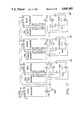
- FIG. 7 is a block diagram of 2-LED continuously variable color display system which includes a memory 76, having a plurality of addressable locations which contain data indicating the portions of red color, and 2-LED color converter circuit 57 for controlling the red bus 5 and green bus 6 of the 2-LED variable color display 42. Means may be provided for selectively addressing the memory locations to extract data therefrom.
- FIG. 8 is a block diagram of 3-LED continuously variable color display system which differs from the like system shown in FIG. 7 in that a 3-LED color converter circuit 58 is utilized to control the red bus 5, green bus 6, and blue bus 7 of the 3-LED variable color display 43.
- the display system also includes a memory 76a, which contains data indicating the portions of red color, a memory 76b, which contains data indicating the portions of green color, and a memory 76c, which contains data indicating the portions of blue color.
- the output data of the memory 76a are applied to the red color converter 59a which will develop control signals for the red bus 5 of the variable color display 43.
- the output data of the memory 76b are applied to the green color converter 59b which will develop control signals for the green bus 6 of the display 43.
- the output data of the memory 76c are applied to the blue color converter 59c which will develop control signals for the blue bus 7 of the display 43.
- a clock signal 99b of a suitable frequency (e.g., 10 kHz), to provide a flicker-free display, is applied to the Clock Pulse inputs CP of the 8-bit binary counters 71e, 71f to step same down.
- the Terminal Count output TC of the counter 71e will drop to a low logic level for one clock cycle, to indicate that the lowest count was reached.
- the negative pulse 99c at the TC output of the counter 71e which is connected to the Parallel Load input PL of the counter 71f, will cause the instant data at the outputs of the memory 76 to be loaded into the counter 71f.
- the data at the memory represent the portion of red color; the portion of green color is complementary.
- the rising edge of the TC pulse 99c triggers the flip-flop 73 into its set condition wherein its output Q rises to a high logic level.
- the counter 71f will count down, from the loaded value, until it reaches zero count, at which moment its TC output drops to a low logic level.
- the negative pulse at the TC output of the counter 71f which is connected to the Clear Direct input CD of the flip-flop 73, causes the latter to be reset and to remain in its reset condition until it is set again at the beginning of the next 256-count cycle. It is thus obvious that the Q output of the flip-flop 73 will be at a high logic level for a period of time proportional to the data initially loaded into the counter 71f.
- the complementary output Q will be at a high logic level for a complementary period of time.
- the Q and Q outputs of the flip-flop 73 are connected to the red bus 5 and green bus 6, repeatedly, via suitable buffers 63a, 63b, shown in detail in FIG. 5, to energize the buses for variable time periods, depending on the data stored in the memory 76.
- any digit between 0 and 9 may be selectively displayed in red color by applying appropriate BCD code to the inputs A0, A1, A2, A3 of the common cathode 7-segment decoder driver 23.
- BCD code 0111 is applied to the inputs A0, A1, A2, A3.
- the decoder develops high voltage levels at its outputs a, b, c, to illuminate equally designated segments, and low voltage levels at all remaining outputs, to extinguish all remaining segments.
- the current flows from the output a of the decoder 23, via red LED 2a and red bus 5, to the current sinking output of the buffer 63a.
- the current flows from the output b of the decoder 23, via red LED 2b and red bus 5, to the output of the buffer 63a.
- the current flows from the output c of the decoder 23, via red LED 2c and red bus 5, to the output of the buffer 63a.
- the green bus To display a number ⁇ 7 ⁇ in green color, the green bus must be energized by raising its input GB to a high logic level.
- the current flows from the output a of the decoder 23, via green LED 3a and green bus 6, to the current sinking output of the buffer 63b.
- the current flows from the output b of the decoder 23, via green LED 3b and green bus 6, to the output of the buffer 63b.
- the current flows from the output c of the decoder 23, via green LED 3c and green bus 6, to the output of the buffer 63b.
- the segments a, b, c illuminate in green color.
- the EXAMPLE 1 considers memory data ⁇ FD ⁇ , in a standard hexadecimal notation, to generate light of substantially red color.
- the pulse 99c loads the data ⁇ FD ⁇ into the counter 71f.
- the flip-flop 73 is set by the rising edge of the pulse 99c.
- the counter 71f will be thereafter stepped down, by clock pulses 99b, until it reaches zero count, 2 clock cycles before the end of the counter cycle.
- a short negative pulse 99d will be produced at its output TC to reset the flip-flop 73, which will remain reset for 2 clock cycles and will be set again by the pulse 99c at the beginning of the next counter cycle, which will repeat the process.
- the flip-flop 73 was set for 254 clock cycles, or about 99% of the time, and reset for 2 clock cycles, or about 1% of the time. Accordingly, the red bus 5 of the display 42 will be energized for about 99% of the time, and the green bus 6 will be energized for the remaining about 1% of the time. As a result, the display 42 will illuminate in substantially red color.
- the EXAMPLE 2 considers memory data ⁇ 02 ⁇ (HEX) to generate light of substantially green color.
- the data ⁇ 02 ⁇ are loaded into the counter 71f, and, simultaneously, the flip-flop 73 is set.
- the counter 71f will count down and will reach zero count after 2 clock cycles. At that instant it will produce at its output TC a negative pulse 99e to reset the flip-flop 73.
- the flip-flop 73 was set for 2 clock cycles, or about 1% of the time, and reset for 254 clock cycles, or about 99% of the time. Accordingly, the red bus 5 of the display 42 will be energized for about 1% of the time, and the green bus 6 will be energized for the remaining about 99% of the time. As a result, the display 42 will illuminate in substantially green color.
- the EXAMPLE 3 considers memory data ⁇ 80 ⁇ (HEX) to generate light of substantially yellow color.
- the data ⁇ 80 ⁇ are loaded into the counter 71f, and, simultaneously, the flip-flop 73 is set.
- the counter 71f will count down and will reach zero count after 128 clock cycles. At that instant it will produce at its output TC a negative pulse 99f to reset the flip-flop 73.
- the flip-flop 73 was set for 128 clock cycles, or about 50% of the time, and reset for 128 clock cycles, or about 50% of the time. Accordingly, the red bus 5 of the display 42 will be energized for about 50% of the time, and the green bus 6 will be energized for the remaining about 50% of the time.
- a clock signal 99b is applied to the CP inputs of the counters 71d, 71a, 71b, 71c, to step same down. Every 256 counts a negative pulse 99c is generated at the TC output of the counter 71d, to load data into the counters 71a, 71b, 71c from respective memories 76a, 76b, 76c and to set the flip-flops 73a, 73b, 73c.
- the data in the red memory 76a represent the portions of red color
- the data in the green memory 76b represent the portions of green color
- the data in the blue memory 76c represent the portions of blue color to be blended.
- the counters 71a, 71b, 71c will count down, from the respective loaded values, until zero counts are reached. When the respective values of the loaded data are different, the length of time of the count-down will be different for each counter. When a particular counter reaches zero count, its TC output momentarily drops to a low logic level, to reset its associated flip-flop (the red counter 71a resets its red flip-flop 73a, etc.). Eventually, all three flip-flops 73a, 73b, 73c will be reset.
- the Q outputs of the flip-flops 73a, 73b, 73c are connected to the red bus 5, green bus 6, and blue bus 7, respectively, via suitable buffers 62a, 62b, 62c, as shown in FIG. 6, to energize the buses for variable periods of time.
- any digit between 0 and 9 may be selectively displayed in red color by applying appropriate BCD code to the inputs A0, A1, A2, A3 of the common anode 7-segment decoder driver 24.
- BCD code 0001 is applied to the inputs A0, A1, A2, A3.
- the decoder develops low logic levels at its outputs b, c, to illuminate equally designated segments, and high logic levels at all remaining outputs, to extinguish all remaining segments.
- the current flows from the output of the buffer 62a, via red bus 5 and red LED 2b, to the output b of the decoder 24, and, via red LED 2c, to the output c of the decoder 24.
- the segments b, c illuminate in red color, thereby causing a visual impression of a character ⁇ 1 ⁇ .
- the green bus To display a number ⁇ 1 ⁇ in green color, the green bus must be energized by raising its input GB to a high logic level. The current flows from the output of the buffer 62b, via green bus 6 and green LED 3b, to the output b of the decoder 24, and, via green LED 3c, to the output c of the decoder 24. As a result, the segments b, c illuminate in green color.
- the blue bus To display a number ⁇ 1 ⁇ in blue color, the blue bus must be energized by raising its input BB to a high logic level. The current flows from the output of the buffer 62c, via blue bus 7 and blue LED 4b, to the output b of the decoder 24, and, via blue LED 4c, to the output c of the decoder 24. As a result, the segments b, c illuminate in blue color.
- the red, green, and blue buses may be repeatedly energized for selective time periods, at a relatively fast rate, as will be more fully explained subsequently.
- the EXAMPLE 4 considers red memory data ⁇ 80 ⁇ , green memory data ⁇ 00 ⁇ , and blue memory data ⁇ 80 ⁇ , all in hexadecimal notation, to generate light of substantially purple color.
- the pulse 99c simultaneously loads the data ⁇ 80 ⁇ from the red memory 76a into the red counter 71a, data ⁇ 00 ⁇ from the green memory 76b into the green counter 71b, and data ⁇ 80 ⁇ from the blue memory 76c into the blue counter 71c.
- the counters 71a, 71b, 71c will be thereafter stepped down.
- the red counter 71a will reach its zero count after 128 clock cycles; the green counter 71b will reach its zero count immediately; the blue counter 71c will reach its zero count after 128 clock cycles.
- the red flip-flop 73a was set for 128 clock cycles, or about 50% of the time
- the green flip-flop 73b was never set
- the blue flip-flop 73c was set for 128 clock cycles, or about 50% of the time. Accordingly, the red bus 5 of the display 43 will be energized for about 50% of the time, green bus 6 will never be energized, and blue bus 7 will be energized for about 50% of the time. As a result of blending substantially equal portions of red and blue colors, the display 43 will illuminate in substantially purple color.
- the EXAMPLE 5 considers red memory data ⁇ 00 ⁇ , green memory data ⁇ 80 ⁇ , and blue memory data ⁇ 80 ⁇ , to generate light of substantially blue-green color.
- the data ⁇ 00 ⁇ are loaded into the red counter 71a
- data ⁇ 80 ⁇ are loaded into the green counter 71b
- data ⁇ 80 ⁇ are loaded into the blue counter 71c.
- the red counter 71a will reach its zero count immediately
- the green counter 71b will reach its zero count after 128 clock cycles, and so will the blue counter 71c.
- the red flip-flop 73a was never set, the green flip-flop 73b was set for 128 clock cycles, or about 50% of the time, and so was the blue flip-flop 73c. Accordingly, the green bus 5 of the display 43 will be energized for about 50% of the time, and so will be the blue bus. As a result, the display 43 will illuminate in substantially blue-green color.
- the EXAMPLE 6 considers red memory data ⁇ 40 ⁇ , green memory data ⁇ 40 ⁇ , and blue memory data ⁇ 80 ⁇ , to generate light of substantially cyan color.
- the data ⁇ 40 ⁇ are loaded into the red counter 71a
- data ⁇ 40 ⁇ are loaded into the green counter 71b
- data ⁇ 80 ⁇ are loaded into the blue counter 71c.
- the red counter 71a will reach its zero count after 64 clock cycles, and so will the green counter 71b.
- the blue counter 71c will reach its zero count after 128 clock cycles.
- the red flip-flop 73a was set for 64 clock cycles, or about 25% of the time, and so was the green flip-flop 73b.
- the blue flip-flop 73c was set for 128 clock cycles, or about 50% of the time. Accordingly, the red bus 5 and green bus 6 of the display 43 will be energized for about 25% of the time, and the blue bus 7 will be energized for about 50% of the time. As a result of blending about 50% of blue color, 25% of red color, and 25% of green color, the display 43 will illuminate in substantially cyan color.
- the EXAMPLE 7 considers red memory data ⁇ 80 ⁇ , green memory data ⁇ 40 ⁇ , and blue memory data ⁇ 40 ⁇ , to generate light of substantially magenta color.
- the data ⁇ 80 ⁇ are loaded into the red counter 71a
- data ⁇ 40 ⁇ are loaded into the green counter 71b
- data ⁇ 40 ⁇ are loaded into the blue counter 71c.
- the red counter 71a will reach its zero count after 128 clock cycles
- the green counter 71b will reach its zero count after 64 clock cycles, and so will the blue counter 71c.
- the red flip-flop 73a was set for 128 clock cycles, or about 50% of the time
- the green flip-flop 73b and blue flip-flop 73c were set for 64 clock cycles, or about 25% of the time. Accordingly, the red bus 5 of the display 43 will be energized for about 50% of the time, green bus 6 and blue bus 7 will be energized for about 25% of the time. As a result, the display 43 will illuminate in substantially magenta color.
- the data values stored in the red, green, and blue memories may be so designed that the sums of the red data, green data, and blue data are constant for all memory addresses, to provide uniform light intensities for all colors.
- data stored in the red, green, and blue memories may be modified in order to compensate for different efficiencies of red, green, and blue LEDs.
- data values for a low efficiency LED may be proportionally incremented such that time of energization is proportionally increased, to effectively provide equal luminances for LEDs of unequal efficiencies.
- variable color display device comprising a plurality of variable color display areas arranged in a pattern and adapted to be illuminated in groups in a selected color to selectively exhibit a plurality of display units.
- Each display area includes a plurality of light sources for emitting upon activation light signals of respectively different primary colors and means for combining the light signals in each display area to obtain a composite light signal of a composite color.
- a first primary color bus is provided to which the light sources in the display areas for emitting light signals of a first primary color are commonly coupled.
- At least a second primary color bus is provided to which the light sources in the display areas for emitting light signals of a second primary color are commonly coupled.
- Data representing portions of the primary colors are stored at assigned locations in a memory.
- Color control circuits repeatedly activate the primary color buses for selective time periods, in accordance with data stored in the memory, to illuminate the display areas in a desired color.
- the color control circuits include counters for repetitively extracting data from the memories as counting values, for decrementing the counting values, and for developing control signals when a predetermined counting value is reached.
- the primary color buses are activated for time periods starting when the data are extracted and ending when respective control signals occur.
Abstract
Description
CORRELATION TABLE ______________________________________ This is a correlation table of reference characters used in the drawings herein, their descriptions, and examples of commercially available parts. # DESCRIPTION EXAMPLE ______________________________________ 2red LED 3green LED 4blue LED 5red bus 6green bus 7blue bus 15segment body 16light scattering material 23 common cathode 7-segment decoder 74LS49 24 common anode 7-segment decoder 74LS47 42 variable color 7-segment display (2 LEDs) 43 variable color 7-segment display (3 LEDs) 57 2-primary color converter 58 3-primary color converter 59 single color converter 62 non-inverting buffer 74LS244 63 inverting buffer 74LS240 64 inverter part of 74LS240,4 71 8-bit counter 74F579 73 D type flip-flop 74HC74 76 memory 99 pulse ______________________________________
Claims (8)
Priority Applications (2)
| Application Number | Priority Date | Filing Date | Title |
|---|---|---|---|
| US06/922,847 US4845481A (en) | 1986-01-08 | 1986-10-24 | Continuously variable color display device |
| US07/322,341 US4965561A (en) | 1986-01-08 | 1989-03-13 | Continuously variable color optical device |
Applications Claiming Priority (2)
| Application Number | Priority Date | Filing Date | Title |
|---|---|---|---|
| US06/817,114 US4647217A (en) | 1986-01-08 | 1986-01-08 | Variable color digital timepiece |
| US06/922,847 US4845481A (en) | 1986-01-08 | 1986-10-24 | Continuously variable color display device |
Related Parent Applications (1)
| Application Number | Title | Priority Date | Filing Date |
|---|---|---|---|
| US06/817,114 Division US4647217A (en) | 1986-01-08 | 1986-01-08 | Variable color digital timepiece |
Related Child Applications (1)
| Application Number | Title | Priority Date | Filing Date |
|---|---|---|---|
| US07/322,341 Division US4965561A (en) | 1986-01-08 | 1989-03-13 | Continuously variable color optical device |
Publications (1)
| Publication Number | Publication Date |
|---|---|
| US4845481A true US4845481A (en) | 1989-07-04 |
Family
ID=27124142
Family Applications (1)
| Application Number | Title | Priority Date | Filing Date |
|---|---|---|---|
| US06/922,847 Expired - Lifetime US4845481A (en) | 1986-01-08 | 1986-10-24 | Continuously variable color display device |
Country Status (1)
| Country | Link |
|---|---|
| US (1) | US4845481A (en) |
Cited By (142)
| Publication number | Priority date | Publication date | Assignee | Title |
|---|---|---|---|---|
| US4965561A (en) * | 1986-01-08 | 1990-10-23 | Karel Havel | Continuously variable color optical device |
| US5084698A (en) * | 1989-02-16 | 1992-01-28 | Vdo Adolf Schindling Ag | Illuminated pointer instrument |
| US5134387A (en) * | 1989-11-06 | 1992-07-28 | Texas Digital Systems, Inc. | Multicolor display system |
| US5612711A (en) * | 1994-03-18 | 1997-03-18 | Tally Display Corporation | Display system |
| US5742265A (en) * | 1990-12-17 | 1998-04-21 | Photonics Systems Corporation | AC plasma gas discharge gray scale graphic, including color and video display drive system |
| US5995012A (en) * | 1997-03-14 | 1999-11-30 | Samsung Electronics Co., Ltd. | System status displaying device |
| US6016038A (en) * | 1997-08-26 | 2000-01-18 | Color Kinetics, Inc. | Multicolored LED lighting method and apparatus |
| US6208322B1 (en) * | 1986-01-15 | 2001-03-27 | Texas Digital Systems, Inc. | Color control signal converter |
| US6211626B1 (en) | 1997-08-26 | 2001-04-03 | Color Kinetics, Incorporated | Illumination components |
| US6209913B1 (en) * | 1997-12-04 | 2001-04-03 | Kabushiki Kaisha Toyoda Jidoshokki Seisakusho | Axle pivot control apparatus for industrial vehicles |
| US6292901B1 (en) | 1997-08-26 | 2001-09-18 | Color Kinetics Incorporated | Power/data protocol |
| US20020044066A1 (en) * | 2000-07-27 | 2002-04-18 | Dowling Kevin J. | Lighting control using speech recognition |
| US6380916B1 (en) * | 1998-04-22 | 2002-04-30 | Hyundai Display Technology Inc. | Color adjustment circuit for liquid crystal display |
| US6414662B1 (en) | 1999-10-12 | 2002-07-02 | Texas Digital Systems, Inc. | Variable color complementary display device using anti-parallel light emitting diodes |
| US6459919B1 (en) | 1997-08-26 | 2002-10-01 | Color Kinetics, Incorporated | Precision illumination methods and systems |
| US20020190975A1 (en) * | 2001-06-15 | 2002-12-19 | Apple Computers, Inc. | Computing device with dynamic ornamental appearance |
| US20030002246A1 (en) * | 2001-06-15 | 2003-01-02 | Apple Computers, Inc. | Active enclousure for computing device |
| US6528954B1 (en) | 1997-08-26 | 2003-03-04 | Color Kinetics Incorporated | Smart light bulb |
| US6548967B1 (en) | 1997-08-26 | 2003-04-15 | Color Kinetics, Inc. | Universal lighting network methods and systems |
| US6577080B2 (en) | 1997-08-26 | 2003-06-10 | Color Kinetics Incorporated | Lighting entertainment system |
| US6608453B2 (en) | 1997-08-26 | 2003-08-19 | Color Kinetics Incorporated | Methods and apparatus for controlling devices in a networked lighting system |
| US20030156429A1 (en) * | 2002-02-15 | 2003-08-21 | Macdonald Joel | Hair ornament having a plurality of optic fibers and three primary color light-emitting diodes |
| US6624597B2 (en) | 1997-08-26 | 2003-09-23 | Color Kinetics, Inc. | Systems and methods for providing illumination in machine vision systems |
| US20030218537A1 (en) * | 2002-05-21 | 2003-11-27 | Lightspace Corporation | Interactive modular system |
| US6690343B2 (en) | 1986-07-07 | 2004-02-10 | Texas Digital Systems, Inc. | Display device with variable color background for evaluating displayed value |
| EP1391650A2 (en) | 1998-09-04 | 2004-02-25 | Wynne Willson Gottelier Limited | Apparatus and method for providing a linear effect |
| US6717376B2 (en) | 1997-08-26 | 2004-04-06 | Color Kinetics, Incorporated | Automotive information systems |
| US6720745B2 (en) | 1997-08-26 | 2004-04-13 | Color Kinetics, Incorporated | Data delivery track |
| US20040113568A1 (en) * | 2000-09-01 | 2004-06-17 | Color Kinetics, Inc. | Systems and methods for providing illumination in machine vision systems |
| US6774584B2 (en) | 1997-08-26 | 2004-08-10 | Color Kinetics, Incorporated | Methods and apparatus for sensor responsive illumination of liquids |
| US20040156192A1 (en) * | 2001-06-15 | 2004-08-12 | Apple Computer, Inc. | Active enclosure for computing device |
| US20040155609A1 (en) * | 1997-12-17 | 2004-08-12 | Color Kinetics, Incorporated | Data delivery track |
| US6777891B2 (en) | 1997-08-26 | 2004-08-17 | Color Kinetics, Incorporated | Methods and apparatus for controlling devices in a networked lighting system |
| US6781329B2 (en) | 1997-08-26 | 2004-08-24 | Color Kinetics Incorporated | Methods and apparatus for illumination of liquids |
| US6788011B2 (en) | 1997-08-26 | 2004-09-07 | Color Kinetics, Incorporated | Multicolored LED lighting method and apparatus |
| US6801003B2 (en) | 2001-03-13 | 2004-10-05 | Color Kinetics, Incorporated | Systems and methods for synchronizing lighting effects |
| US20040207341A1 (en) * | 2003-04-14 | 2004-10-21 | Carpenter Decorating Co., Inc. | Decorative lighting system and decorative illumination device |
| US20050036300A1 (en) * | 2000-09-27 | 2005-02-17 | Color Kinetics, Inc. | Methods and systems for illuminating household products |
| US20050040773A1 (en) * | 1998-03-19 | 2005-02-24 | Ppt Vision, Inc. | Method and apparatus for a variable intensity pulsed L.E.D. light |
| US20050047130A1 (en) * | 2003-08-29 | 2005-03-03 | Waters Michael A. | Picture light apparatus and method |
| US20050047132A1 (en) * | 1997-08-26 | 2005-03-03 | Color Kinetics, Inc. | Systems and methods for color changing device and enclosure |
| US6869204B2 (en) | 1997-08-26 | 2005-03-22 | Color Kinetics Incorporated | Light fixtures for illumination of liquids |
| US6897624B2 (en) | 1997-08-26 | 2005-05-24 | Color Kinetics, Incorporated | Packaged information systems |
| US20050134529A1 (en) * | 2003-12-18 | 2005-06-23 | Luiz Lei | Color changing segmented display |
| US20050162090A1 (en) * | 2004-01-22 | 2005-07-28 | Siemens Vdo Automotive Corporation | Illuminated display having two single-colored light sources |
| US6936978B2 (en) | 1997-08-26 | 2005-08-30 | Color Kinetics Incorporated | Methods and apparatus for remotely controlled illumination of liquids |
| US20050225757A1 (en) * | 2002-08-01 | 2005-10-13 | Cunningham David W | Method for controlling the luminous flux spectrum of a lighting fixture |
| US20050232132A1 (en) * | 2004-04-19 | 2005-10-20 | Tir Systems Ltd. | Parallel pulse code modulation system and method |
| US6965205B2 (en) | 1997-08-26 | 2005-11-15 | Color Kinetics Incorporated | Light emitting diode based products |
| US6967448B2 (en) | 1997-08-26 | 2005-11-22 | Color Kinetics, Incorporated | Methods and apparatus for controlling illumination |
| US20050270733A1 (en) * | 1999-05-14 | 2005-12-08 | Apple Computer, Inc. | Display housing for computing device |
| US6975079B2 (en) | 1997-08-26 | 2005-12-13 | Color Kinetics Incorporated | Systems and methods for controlling illumination sources |
| US20060001598A1 (en) * | 2004-06-30 | 2006-01-05 | Luiz Lei | Multi-color segmented display |
| US20060016960A1 (en) * | 1999-09-29 | 2006-01-26 | Color Kinetics, Incorporated | Systems and methods for calibrating light output by light-emitting diodes |
| EP1631126A2 (en) | 2004-08-25 | 2006-03-01 | Space Cannon VH S.p.A. | Control system for illumination devices |
| US7014336B1 (en) | 1999-11-18 | 2006-03-21 | Color Kinetics Incorporated | Systems and methods for generating and modulating illumination conditions |
| US7038398B1 (en) | 1997-08-26 | 2006-05-02 | Color Kinetics, Incorporated | Kinetic illumination system and methods |
| US7038399B2 (en) | 2001-03-13 | 2006-05-02 | Color Kinetics Incorporated | Methods and apparatus for providing power to lighting devices |
| US20060104058A1 (en) * | 2004-03-15 | 2006-05-18 | Color Kinetics Incorporated | Methods and apparatus for controlled lighting based on a reference gamut |
| US7064498B2 (en) * | 1997-08-26 | 2006-06-20 | Color Kinetics Incorporated | Light-emitting diode based products |
| US7113541B1 (en) | 1997-08-26 | 2006-09-26 | Color Kinetics Incorporated | Method for software driven generation of multiple simultaneous high speed pulse width modulated signals |
| US20060256037A1 (en) * | 2001-06-15 | 2006-11-16 | Apple Computer, Inc. | Active enclosure for computing device |
| US20060274421A1 (en) * | 2005-06-07 | 2006-12-07 | Jeffrey Okamitsu | Solid-state light sources for curing and surface modification |
| US20070020573A1 (en) * | 1999-12-21 | 2007-01-25 | Furner Paul E | Candle assembly with light emitting system |
| US20070031555A1 (en) * | 2005-08-05 | 2007-02-08 | Axelrod Glen S | Direct starch molding |
| US7178941B2 (en) | 2003-05-05 | 2007-02-20 | Color Kinetics Incorporated | Lighting methods and systems |
| US7187141B2 (en) | 1997-08-26 | 2007-03-06 | Color Kinetics Incorporated | Methods and apparatus for illumination of liquids |
| US7202613B2 (en) | 2001-05-30 | 2007-04-10 | Color Kinetics Incorporated | Controlled lighting methods and apparatus |
| US20070115273A1 (en) * | 2005-11-14 | 2007-05-24 | Inova Solutions, Inc. | Low power LED visual messaging device, system and method |
| US7231060B2 (en) | 1997-08-26 | 2007-06-12 | Color Kinetics Incorporated | Systems and methods of generating control signals |
| US7235792B2 (en) | 2004-05-19 | 2007-06-26 | Carl Scott Elofson | Color-tuned volumetric light using high quantum yield nanocrystals |
| US7242152B2 (en) | 1997-08-26 | 2007-07-10 | Color Kinetics Incorporated | Systems and methods of controlling light systems |
| US20070159110A1 (en) * | 2004-07-13 | 2007-07-12 | Weng Ming B | Shoe lamp device with multiple voltage levels |
| US20070236156A1 (en) * | 2001-05-30 | 2007-10-11 | Color Kinetics Incorporated | Methods and apparatus for controlling devices in a networked lighting system |
| US7300192B2 (en) | 2002-10-03 | 2007-11-27 | Color Kinetics Incorporated | Methods and apparatus for illuminating environments |
| US20070292812A1 (en) * | 1999-12-21 | 2007-12-20 | Furner Paul E | Candle assembly with light emitting system |
| US7352339B2 (en) | 1997-08-26 | 2008-04-01 | Philips Solid-State Lighting Solutions | Diffuse illumination systems and methods |
| US20080084327A1 (en) * | 2005-10-25 | 2008-04-10 | John Rubis | Multicolor illumination system |
| US7358679B2 (en) | 2002-05-09 | 2008-04-15 | Philips Solid-State Lighting Solutions, Inc. | Dimmable LED-based MR16 lighting apparatus and methods |
| US7385359B2 (en) | 1997-08-26 | 2008-06-10 | Philips Solid-State Lighting Solutions, Inc. | Information systems |
| US7405715B2 (en) | 2001-08-09 | 2008-07-29 | Guzman Robert G | LED light apparatus with instantly adjustable color intensity |
| US20080204268A1 (en) * | 2000-04-24 | 2008-08-28 | Philips Solid-State Lighting Solutions | Methods and apparatus for conveying information via color of light |
| US7427840B2 (en) | 1997-08-26 | 2008-09-23 | Philips Solid-State Lighting Solutions, Inc. | Methods and apparatus for controlling illumination |
| US7443388B1 (en) | 1999-05-14 | 2008-10-28 | Apple Inc. | Housing for a computing device |
| US20080272941A1 (en) * | 2007-05-02 | 2008-11-06 | Verne Stephen Jackson | System of multi-channel analog signal generation and controlled activation of multiple peripheral devices |
| US7482764B2 (en) | 1997-08-26 | 2009-01-27 | Philips Solid-State Lighting Solutions, Inc. | Light sources for illumination of liquids |
| US20090056183A1 (en) * | 2007-08-27 | 2009-03-05 | E-Llumineering Llc | Display sign adapted to be backlit by widely spaced light emitting diodes |
| US20090140660A1 (en) * | 1998-02-04 | 2009-06-04 | Aptina Imaging Corporation | Pulse-controlled light emitting diode source |
| US20090159919A1 (en) * | 2007-12-20 | 2009-06-25 | Altair Engineering, Inc. | Led lighting apparatus with swivel connection |
| US7572028B2 (en) | 1999-11-18 | 2009-08-11 | Philips Solid-State Lighting Solutions, Inc. | Methods and apparatus for generating and modulating white light illumination conditions |
| US7598686B2 (en) | 1997-12-17 | 2009-10-06 | Philips Solid-State Lighting Solutions, Inc. | Organic light emitting diode methods and apparatus |
| US7633405B2 (en) | 2005-11-14 | 2009-12-15 | Inova Solutions, Inc. | Low power LED visual messaging device, system and method |
| US20100008085A1 (en) * | 2008-07-09 | 2010-01-14 | Altair Engineering, Inc. | Method of forming led-based light and resulting led-based light |
| US20100027259A1 (en) * | 2008-07-31 | 2010-02-04 | Altair Engineering, Inc. | Fluorescent tube replacement having longitudinally oriented leds |
| US7659674B2 (en) | 1997-08-26 | 2010-02-09 | Philips Solid-State Lighting Solutions, Inc. | Wireless lighting control methods and apparatus |
| US20100052542A1 (en) * | 2008-09-02 | 2010-03-04 | Altair Engineering, Inc. | Led lamp failure alerting system |
| US20100072920A1 (en) * | 2008-09-24 | 2010-03-25 | Industrial Technology Research Institute | Drive system for illumination device |
| US7699603B2 (en) | 1999-12-21 | 2010-04-20 | S.C. Johnson & Son, Inc. | Multisensory candle assembly |
| US20100102730A1 (en) * | 2008-10-24 | 2010-04-29 | Altair Engineering, Inc. | Light and light sensor |
| US20100103673A1 (en) * | 2008-10-24 | 2010-04-29 | Altair Engineering, Inc. | End cap substitute for led-based tube replacement light |
| US20100106306A1 (en) * | 2008-10-24 | 2010-04-29 | Altair Engineering, Inc. | Integration of led lighting with building controls |
| US20100103664A1 (en) * | 2008-10-24 | 2010-04-29 | Altair Engineering, Inc. | Lighting including integral communication apparatus |
| US7740371B1 (en) | 1998-03-19 | 2010-06-22 | Charles A. Lemaire | Method and apparatus for pulsed L.E.D. illumination for a camera |
| US20100172149A1 (en) * | 2007-12-21 | 2010-07-08 | Altair Engineering, Inc. | Light distribution using a light emitting diode assembly |
| US20100177532A1 (en) * | 2009-01-15 | 2010-07-15 | Altair Engineering, Inc. | Led lens |
| US20100181933A1 (en) * | 2009-01-21 | 2010-07-22 | Altair Engineering, Inc. | Direct ac-to-dc converter for passive component minimization and universal operation of led arrays |
| US20100181925A1 (en) * | 2009-01-21 | 2010-07-22 | Altair Engineering, Inc. | Ballast/Line Detection Circuit for Fluorescent Replacement Lamps |
| US7764026B2 (en) | 1997-12-17 | 2010-07-27 | Philips Solid-State Lighting Solutions, Inc. | Systems and methods for digital entertainment |
| US7845823B2 (en) | 1997-08-26 | 2010-12-07 | Philips Solid-State Lighting Solutions, Inc. | Controlled lighting methods and apparatus |
| US20100320922A1 (en) * | 2009-06-23 | 2010-12-23 | Altair Engineering, Inc. | Illumination device including leds and a switching power control system |
| US20100321921A1 (en) * | 2009-06-23 | 2010-12-23 | Altair Engineering, Inc. | Led lamp with a wavelength converting layer |
| US20110080111A1 (en) * | 2009-10-07 | 2011-04-07 | Lutron Electronics Co., Inc. | Configurable load control device for light-emitting diode light sources |
| US8256924B2 (en) | 2008-09-15 | 2012-09-04 | Ilumisys, Inc. | LED-based light having rapidly oscillating LEDs |
| WO2012125625A1 (en) | 2011-03-15 | 2012-09-20 | Lutron Electronics Co., Inc. | Load control device for a light-emitting diode light source |
| US8299695B2 (en) | 2009-06-02 | 2012-10-30 | Ilumisys, Inc. | Screw-in LED bulb comprising a base having outwardly projecting nodes |
| US8330381B2 (en) | 2009-05-14 | 2012-12-11 | Ilumisys, Inc. | Electronic circuit for DC conversion of fluorescent lighting ballast |
| US8360599B2 (en) | 2008-05-23 | 2013-01-29 | Ilumisys, Inc. | Electric shock resistant L.E.D. based light |
| US8362700B2 (en) | 2003-12-23 | 2013-01-29 | Richmond Simon N | Solar powered light assembly to produce light of varying colors |
| US8454193B2 (en) | 2010-07-08 | 2013-06-04 | Ilumisys, Inc. | Independent modules for LED fluorescent light tube replacement |
| US8523394B2 (en) | 2010-10-29 | 2013-09-03 | Ilumisys, Inc. | Mechanisms for reducing risk of shock during installation of light tube |
| US8540401B2 (en) | 2010-03-26 | 2013-09-24 | Ilumisys, Inc. | LED bulb with internal heat dissipating structures |
| US8541958B2 (en) | 2010-03-26 | 2013-09-24 | Ilumisys, Inc. | LED light with thermoelectric generator |
| US8596813B2 (en) | 2010-07-12 | 2013-12-03 | Ilumisys, Inc. | Circuit board mount for LED light tube |
| US8653984B2 (en) | 2008-10-24 | 2014-02-18 | Ilumisys, Inc. | Integration of LED lighting control with emergency notification systems |
| US20140062689A1 (en) * | 2012-08-29 | 2014-03-06 | Yao Hung Huang | Vehicle Rear Light Assembly |
| US8866396B2 (en) | 2000-02-11 | 2014-10-21 | Ilumisys, Inc. | Light tube and power supply circuit |
| US8870415B2 (en) | 2010-12-09 | 2014-10-28 | Ilumisys, Inc. | LED fluorescent tube replacement light with reduced shock hazard |
| US8901823B2 (en) | 2008-10-24 | 2014-12-02 | Ilumisys, Inc. | Light and light sensor |
| US9057493B2 (en) | 2010-03-26 | 2015-06-16 | Ilumisys, Inc. | LED light tube with dual sided light distribution |
| US9072171B2 (en) | 2011-08-24 | 2015-06-30 | Ilumisys, Inc. | Circuit board mount for LED light |
| US9113521B2 (en) | 2013-05-29 | 2015-08-18 | Lutron Electronics Co., Inc. | Load control device for a light-emitting diode light source |
| US9163794B2 (en) | 2012-07-06 | 2015-10-20 | Ilumisys, Inc. | Power supply assembly for LED-based light tube |
| US9184518B2 (en) | 2012-03-02 | 2015-11-10 | Ilumisys, Inc. | Electrical connector header for an LED-based light |
| US9267650B2 (en) | 2013-10-09 | 2016-02-23 | Ilumisys, Inc. | Lens for an LED-based light |
| US9271367B2 (en) | 2012-07-09 | 2016-02-23 | Ilumisys, Inc. | System and method for controlling operation of an LED-based light |
| US9285084B2 (en) | 2013-03-14 | 2016-03-15 | Ilumisys, Inc. | Diffusers for LED-based lights |
| US9420653B2 (en) | 2010-11-19 | 2016-08-16 | Semiconductor Components Industries, Llc | LED driver circuit and method |
| US9510400B2 (en) | 2014-05-13 | 2016-11-29 | Ilumisys, Inc. | User input systems for an LED-based light |
| US9574717B2 (en) | 2014-01-22 | 2017-02-21 | Ilumisys, Inc. | LED-based light with addressed LEDs |
| US10098196B2 (en) | 2016-09-16 | 2018-10-09 | Lutron Electronics Co., Inc. | Load control device for a light-emitting diode light source having different operating modes |
| US10161568B2 (en) | 2015-06-01 | 2018-12-25 | Ilumisys, Inc. | LED-based light with canted outer walls |
| US10321528B2 (en) | 2007-10-26 | 2019-06-11 | Philips Lighting Holding B.V. | Targeted content delivery using outdoor lighting networks (OLNs) |
Citations (8)
| Publication number | Priority date | Publication date | Assignee | Title |
|---|---|---|---|---|
| US3740570A (en) * | 1971-09-27 | 1973-06-19 | Litton Systems Inc | Driving circuits for light emitting diodes |
| US3840873A (en) * | 1972-04-14 | 1974-10-08 | S Usui | Alpha-numeric character display device |
| US3924227A (en) * | 1972-11-13 | 1975-12-02 | Michael Stolov | Digital display device |
| DE3037500A1 (en) * | 1979-10-06 | 1981-04-23 | Zettler-Elektro-Apparate AG, Näfels | LIGHTING DIODE ARRANGEMENT TO DISPLAY LARGE STRUCTURES |
| DE3009416A1 (en) * | 1980-03-12 | 1981-09-17 | Licentia Patent-Verwaltungs-Gmbh, 6000 Frankfurt | Multi-colour LED display for seven segment figures - is used in calculators or measuring instruments and employs transistor or direct switching without supply voltage polarity change |
| US4488149A (en) * | 1981-02-26 | 1984-12-11 | Givens Jr William A | Electronic display having segments wherein each segment is capable of selectively illuminating two colors |
| DD220844A1 (en) * | 1984-01-27 | 1985-04-10 | Werk Fernsehelektronik Veb | DIGITAL ELECTROOPTICAL DISPLAY UNIT |
| GB2158631A (en) * | 1984-04-06 | 1985-11-13 | Comtronic Gmbh | Optical display apparatus |
-
1986
- 1986-10-24 US US06/922,847 patent/US4845481A/en not_active Expired - Lifetime
Patent Citations (8)
| Publication number | Priority date | Publication date | Assignee | Title |
|---|---|---|---|---|
| US3740570A (en) * | 1971-09-27 | 1973-06-19 | Litton Systems Inc | Driving circuits for light emitting diodes |
| US3840873A (en) * | 1972-04-14 | 1974-10-08 | S Usui | Alpha-numeric character display device |
| US3924227A (en) * | 1972-11-13 | 1975-12-02 | Michael Stolov | Digital display device |
| DE3037500A1 (en) * | 1979-10-06 | 1981-04-23 | Zettler-Elektro-Apparate AG, Näfels | LIGHTING DIODE ARRANGEMENT TO DISPLAY LARGE STRUCTURES |
| DE3009416A1 (en) * | 1980-03-12 | 1981-09-17 | Licentia Patent-Verwaltungs-Gmbh, 6000 Frankfurt | Multi-colour LED display for seven segment figures - is used in calculators or measuring instruments and employs transistor or direct switching without supply voltage polarity change |
| US4488149A (en) * | 1981-02-26 | 1984-12-11 | Givens Jr William A | Electronic display having segments wherein each segment is capable of selectively illuminating two colors |
| DD220844A1 (en) * | 1984-01-27 | 1985-04-10 | Werk Fernsehelektronik Veb | DIGITAL ELECTROOPTICAL DISPLAY UNIT |
| GB2158631A (en) * | 1984-04-06 | 1985-11-13 | Comtronic Gmbh | Optical display apparatus |
Non-Patent Citations (4)
| Title |
|---|
| Bill Wagner, 2 Color LED Driver Versatile Visual Effects, Oct. 20, 1980, EDN vol. 25, No. 19. * |
| Bill Wagner, 2-Color LED+Driver=Versatile Visual Effects, Oct. 20, 1980, EDN vol. 25, No. 19. |
| IBM Technical Disclosure Bulletin, "Electroluminescent Display", R. W. Landauer, vol. 8, No. 11, Apr., 1966. |
| IBM Technical Disclosure Bulletin, Electroluminescent Display , R. W. Landauer, vol. 8, No. 11, Apr., 1966. * |
Cited By (333)
| Publication number | Priority date | Publication date | Assignee | Title |
|---|---|---|---|---|
| US4965561A (en) * | 1986-01-08 | 1990-10-23 | Karel Havel | Continuously variable color optical device |
| US6424327B2 (en) | 1986-01-15 | 2002-07-23 | Texas Digital Systems, Inc. | Multicolor display element with enable input |
| US6577287B2 (en) | 1986-01-15 | 2003-06-10 | Texas Digital Systems, Inc. | Dual variable color display device |
| US6535186B1 (en) | 1986-01-15 | 2003-03-18 | Texas Digital Systems, Inc. | Multicolor display element |
| US6208322B1 (en) * | 1986-01-15 | 2001-03-27 | Texas Digital Systems, Inc. | Color control signal converter |
| US6690343B2 (en) | 1986-07-07 | 2004-02-10 | Texas Digital Systems, Inc. | Display device with variable color background for evaluating displayed value |
| US5084698A (en) * | 1989-02-16 | 1992-01-28 | Vdo Adolf Schindling Ag | Illuminated pointer instrument |
| US5134387A (en) * | 1989-11-06 | 1992-07-28 | Texas Digital Systems, Inc. | Multicolor display system |
| US5278542A (en) * | 1989-11-06 | 1994-01-11 | Texas Digital Systems, Inc. | Multicolor display system |
| US5742265A (en) * | 1990-12-17 | 1998-04-21 | Photonics Systems Corporation | AC plasma gas discharge gray scale graphic, including color and video display drive system |
| US5612711A (en) * | 1994-03-18 | 1997-03-18 | Tally Display Corporation | Display system |
| US5995012A (en) * | 1997-03-14 | 1999-11-30 | Samsung Electronics Co., Ltd. | System status displaying device |
| US6717376B2 (en) | 1997-08-26 | 2004-04-06 | Color Kinetics, Incorporated | Automotive information systems |
| US6781329B2 (en) | 1997-08-26 | 2004-08-24 | Color Kinetics Incorporated | Methods and apparatus for illumination of liquids |
| US6340868B1 (en) | 1997-08-26 | 2002-01-22 | Color Kinetics Incorporated | Illumination components |
| US7309965B2 (en) | 1997-08-26 | 2007-12-18 | Color Kinetics Incorporated | Universal lighting network methods and systems |
| US7352339B2 (en) | 1997-08-26 | 2008-04-01 | Philips Solid-State Lighting Solutions | Diffuse illumination systems and methods |
| US7253566B2 (en) | 1997-08-26 | 2007-08-07 | Color Kinetics Incorporated | Methods and apparatus for controlling devices in a networked lighting system |
| US7038398B1 (en) | 1997-08-26 | 2006-05-02 | Color Kinetics, Incorporated | Kinetic illumination system and methods |
| US6459919B1 (en) | 1997-08-26 | 2002-10-01 | Color Kinetics, Incorporated | Precision illumination methods and systems |
| US6211626B1 (en) | 1997-08-26 | 2001-04-03 | Color Kinetics, Incorporated | Illumination components |
| US7248239B2 (en) | 1997-08-26 | 2007-07-24 | Color Kinetics Incorporated | Systems and methods for color changing device and enclosure |
| US6528954B1 (en) | 1997-08-26 | 2003-03-04 | Color Kinetics Incorporated | Smart light bulb |
| US6166496A (en) * | 1997-08-26 | 2000-12-26 | Color Kinetics Incorporated | Lighting entertainment system |
| US6548967B1 (en) | 1997-08-26 | 2003-04-15 | Color Kinetics, Inc. | Universal lighting network methods and systems |
| US20030100837A1 (en) * | 1997-08-26 | 2003-05-29 | Ihor Lys | Precision illumination methods and systems |
| US6150774A (en) * | 1997-08-26 | 2000-11-21 | Color Kinetics, Incorporated | Multicolored LED lighting method and apparatus |
| US6577080B2 (en) | 1997-08-26 | 2003-06-10 | Color Kinetics Incorporated | Lighting entertainment system |
| US6608453B2 (en) | 1997-08-26 | 2003-08-19 | Color Kinetics Incorporated | Methods and apparatus for controlling devices in a networked lighting system |
| US7242152B2 (en) | 1997-08-26 | 2007-07-10 | Color Kinetics Incorporated | Systems and methods of controlling light systems |
| US6624597B2 (en) | 1997-08-26 | 2003-09-23 | Color Kinetics, Inc. | Systems and methods for providing illumination in machine vision systems |
| US7385359B2 (en) | 1997-08-26 | 2008-06-10 | Philips Solid-State Lighting Solutions, Inc. | Information systems |
| US6016038A (en) * | 1997-08-26 | 2000-01-18 | Color Kinetics, Inc. | Multicolored LED lighting method and apparatus |
| US7231060B2 (en) | 1997-08-26 | 2007-06-12 | Color Kinetics Incorporated | Systems and methods of generating control signals |
| US20060050509A9 (en) * | 1997-08-26 | 2006-03-09 | Color Kinetics, Inc. | Systems and methods for color changing device and enclosure |
| US6720745B2 (en) | 1997-08-26 | 2004-04-13 | Color Kinetics, Incorporated | Data delivery track |
| US7659674B2 (en) | 1997-08-26 | 2010-02-09 | Philips Solid-State Lighting Solutions, Inc. | Wireless lighting control methods and apparatus |
| US6774584B2 (en) | 1997-08-26 | 2004-08-10 | Color Kinetics, Incorporated | Methods and apparatus for sensor responsive illumination of liquids |
| US7221104B2 (en) | 1997-08-26 | 2007-05-22 | Color Kinetics Incorporated | Linear lighting apparatus and methods |
| US7525254B2 (en) | 1997-08-26 | 2009-04-28 | Philips Solid-State Lighting Solutions, Inc. | Vehicle lighting methods and apparatus |
| US6777891B2 (en) | 1997-08-26 | 2004-08-17 | Color Kinetics, Incorporated | Methods and apparatus for controlling devices in a networked lighting system |
| US6292901B1 (en) | 1997-08-26 | 2001-09-18 | Color Kinetics Incorporated | Power/data protocol |
| US6788011B2 (en) | 1997-08-26 | 2004-09-07 | Color Kinetics, Incorporated | Multicolored LED lighting method and apparatus |
| US20080183081A1 (en) * | 1997-08-26 | 2008-07-31 | Philips Solid-State Lighting Solutions | Precision illumination methods and systems |
| US6806659B1 (en) | 1997-08-26 | 2004-10-19 | Color Kinetics, Incorporated | Multicolored LED lighting method and apparatus |
| US6975079B2 (en) | 1997-08-26 | 2005-12-13 | Color Kinetics Incorporated | Systems and methods for controlling illumination sources |
| US7187141B2 (en) | 1997-08-26 | 2007-03-06 | Color Kinetics Incorporated | Methods and apparatus for illumination of liquids |
| US7427840B2 (en) | 1997-08-26 | 2008-09-23 | Philips Solid-State Lighting Solutions, Inc. | Methods and apparatus for controlling illumination |
| US7845823B2 (en) | 1997-08-26 | 2010-12-07 | Philips Solid-State Lighting Solutions, Inc. | Controlled lighting methods and apparatus |
| US20050047132A1 (en) * | 1997-08-26 | 2005-03-03 | Color Kinetics, Inc. | Systems and methods for color changing device and enclosure |
| US6869204B2 (en) | 1997-08-26 | 2005-03-22 | Color Kinetics Incorporated | Light fixtures for illumination of liquids |
| US6888322B2 (en) | 1997-08-26 | 2005-05-03 | Color Kinetics Incorporated | Systems and methods for color changing device and enclosure |
| US6897624B2 (en) | 1997-08-26 | 2005-05-24 | Color Kinetics, Incorporated | Packaged information systems |
| US7453217B2 (en) | 1997-08-26 | 2008-11-18 | Philips Solid-State Lighting Solutions, Inc. | Marketplace illumination methods and apparatus |
| US7482764B2 (en) | 1997-08-26 | 2009-01-27 | Philips Solid-State Lighting Solutions, Inc. | Light sources for illumination of liquids |
| US7308296B2 (en) | 1997-08-26 | 2007-12-11 | Color Kinetics Incorporated | Precision illumination methods and systems |
| US6936978B2 (en) | 1997-08-26 | 2005-08-30 | Color Kinetics Incorporated | Methods and apparatus for remotely controlled illumination of liquids |
| US7135824B2 (en) | 1997-08-26 | 2006-11-14 | Color Kinetics Incorporated | Systems and methods for controlling illumination sources |
| US7064498B2 (en) * | 1997-08-26 | 2006-06-20 | Color Kinetics Incorporated | Light-emitting diode based products |
| US6965205B2 (en) | 1997-08-26 | 2005-11-15 | Color Kinetics Incorporated | Light emitting diode based products |
| US6967448B2 (en) | 1997-08-26 | 2005-11-22 | Color Kinetics, Incorporated | Methods and apparatus for controlling illumination |
| US7113541B1 (en) | 1997-08-26 | 2006-09-26 | Color Kinetics Incorporated | Method for software driven generation of multiple simultaneous high speed pulse width modulated signals |
| US6209913B1 (en) * | 1997-12-04 | 2001-04-03 | Kabushiki Kaisha Toyoda Jidoshokki Seisakusho | Axle pivot control apparatus for industrial vehicles |
| US7132804B2 (en) | 1997-12-17 | 2006-11-07 | Color Kinetics Incorporated | Data delivery track |
| US7764026B2 (en) | 1997-12-17 | 2010-07-27 | Philips Solid-State Lighting Solutions, Inc. | Systems and methods for digital entertainment |
| US7520634B2 (en) | 1997-12-17 | 2009-04-21 | Philips Solid-State Lighting Solutions, Inc. | Methods and apparatus for controlling a color temperature of lighting conditions |
| US20040155609A1 (en) * | 1997-12-17 | 2004-08-12 | Color Kinetics, Incorporated | Data delivery track |
| US7387405B2 (en) | 1997-12-17 | 2008-06-17 | Philips Solid-State Lighting Solutions, Inc. | Methods and apparatus for generating prescribed spectrums of light |
| US7598686B2 (en) | 1997-12-17 | 2009-10-06 | Philips Solid-State Lighting Solutions, Inc. | Organic light emitting diode methods and apparatus |
| US20110169421A1 (en) * | 1998-02-04 | 2011-07-14 | Round Rock Research, Llc | Method and apparatus for providing illumination with a pulse-controlled light emitting diode source |
| US20090140660A1 (en) * | 1998-02-04 | 2009-06-04 | Aptina Imaging Corporation | Pulse-controlled light emitting diode source |
| US7740371B1 (en) | 1998-03-19 | 2010-06-22 | Charles A. Lemaire | Method and apparatus for pulsed L.E.D. illumination for a camera |
| US8362712B1 (en) | 1998-03-19 | 2013-01-29 | Led Tech Development, Llc | Apparatus and method for L.E.D. illumination |
| US9907137B1 (en) | 1998-03-19 | 2018-02-27 | Lemaire Illumination Technologies, Llc | Pulsed L.E.D. illumination |
| US8829808B1 (en) | 1998-03-19 | 2014-09-09 | Led Tech Development, Llc | Apparatus and method for pulsed L.E.D. illumination |
| US8643305B2 (en) | 1998-03-19 | 2014-02-04 | Lemaire Illumination Technologies, Llc | Apparatus for L.E.D. illumination |
| US20070133199A1 (en) * | 1998-03-19 | 2007-06-14 | Charles Lemaire | Method and apparatus for a pulsed l.e.d. illumination |
| US7393119B2 (en) | 1998-03-19 | 2008-07-01 | Charles A. Lemaire | Method and apparatus for constant light output pulsed L.E.D. illumination |
| US8159146B1 (en) | 1998-03-19 | 2012-04-17 | Lemaire Illumination Technologies, Llc | Apparatus and method for pulsed L.E.D. illumination |
| US7186000B2 (en) * | 1998-03-19 | 2007-03-06 | Lebens Gary A | Method and apparatus for a variable intensity pulsed L.E.D. light |
| US20050040773A1 (en) * | 1998-03-19 | 2005-02-24 | Ppt Vision, Inc. | Method and apparatus for a variable intensity pulsed L.E.D. light |
| US6380916B1 (en) * | 1998-04-22 | 2002-04-30 | Hyundai Display Technology Inc. | Color adjustment circuit for liquid crystal display |
| EP1391650A2 (en) | 1998-09-04 | 2004-02-25 | Wynne Willson Gottelier Limited | Apparatus and method for providing a linear effect |
| US8139349B2 (en) | 1999-05-14 | 2012-03-20 | Apple Inc. | Display housing for computing device |
| US20090257232A1 (en) * | 1999-05-14 | 2009-10-15 | Apple Inc. | Display housing for computing device |
| US7679893B2 (en) | 1999-05-14 | 2010-03-16 | Apple Inc. | Display housing for computing device |
| US7804487B1 (en) | 1999-05-14 | 2010-09-28 | Apple Inc. | Housing for a computing device |
| US8256913B2 (en) | 1999-05-14 | 2012-09-04 | Apple Inc. | Housing for a computing device |
| US20090009947A1 (en) * | 1999-05-14 | 2009-01-08 | Apple Inc. | Display housing for computing device |
| US7440264B2 (en) | 1999-05-14 | 2008-10-21 | Apple Inc. | Display housing for computing device |
| US7724509B2 (en) | 1999-05-14 | 2010-05-25 | Apple Inc. | Display housing for computing device |
| US20050270734A1 (en) * | 1999-05-14 | 2005-12-08 | Apple Computer, Inc. | Display housing for computing device |
| US7443388B1 (en) | 1999-05-14 | 2008-10-28 | Apple Inc. | Housing for a computing device |
| US20050270733A1 (en) * | 1999-05-14 | 2005-12-08 | Apple Computer, Inc. | Display housing for computing device |
| US20050270244A1 (en) * | 1999-05-14 | 2005-12-08 | Apple Computer, Inc. | Display housing for computing device |
| US7460362B2 (en) | 1999-05-14 | 2008-12-02 | Apple Inc. | Display housing for computing device |
| US7482565B2 (en) | 1999-09-29 | 2009-01-27 | Philips Solid-State Lighting Solutions, Inc. | Systems and methods for calibrating light output by light-emitting diodes |
| US20060016960A1 (en) * | 1999-09-29 | 2006-01-26 | Color Kinetics, Incorporated | Systems and methods for calibrating light output by light-emitting diodes |
| US6414662B1 (en) | 1999-10-12 | 2002-07-02 | Texas Digital Systems, Inc. | Variable color complementary display device using anti-parallel light emitting diodes |
| US7959320B2 (en) | 1999-11-18 | 2011-06-14 | Philips Solid-State Lighting Solutions, Inc. | Methods and apparatus for generating and modulating white light illumination conditions |
| US7014336B1 (en) | 1999-11-18 | 2006-03-21 | Color Kinetics Incorporated | Systems and methods for generating and modulating illumination conditions |
| US7350936B2 (en) | 1999-11-18 | 2008-04-01 | Philips Solid-State Lighting Solutions, Inc. | Conventionally-shaped light bulbs employing white LEDs |
| US7255457B2 (en) | 1999-11-18 | 2007-08-14 | Color Kinetics Incorporated | Methods and apparatus for generating and modulating illumination conditions |
| US7572028B2 (en) | 1999-11-18 | 2009-08-11 | Philips Solid-State Lighting Solutions, Inc. | Methods and apparatus for generating and modulating white light illumination conditions |
| US7637737B2 (en) | 1999-12-21 | 2009-12-29 | S.C. Johnson & Son, Inc. | Candle assembly with light emitting system |
| US7699603B2 (en) | 1999-12-21 | 2010-04-20 | S.C. Johnson & Son, Inc. | Multisensory candle assembly |
| US20070020573A1 (en) * | 1999-12-21 | 2007-01-25 | Furner Paul E | Candle assembly with light emitting system |
| US20070292812A1 (en) * | 1999-12-21 | 2007-12-20 | Furner Paul E | Candle assembly with light emitting system |
| US8866396B2 (en) | 2000-02-11 | 2014-10-21 | Ilumisys, Inc. | Light tube and power supply circuit |
| US9759392B2 (en) | 2000-02-11 | 2017-09-12 | Ilumisys, Inc. | Light tube and power supply circuit |
| US10054270B2 (en) | 2000-02-11 | 2018-08-21 | Ilumisys, Inc. | Light tube and power supply circuit |
| US9970601B2 (en) | 2000-02-11 | 2018-05-15 | Ilumisys, Inc. | Light tube and power supply circuit |
| US9803806B2 (en) | 2000-02-11 | 2017-10-31 | Ilumisys, Inc. | Light tube and power supply circuit |
| US8870412B1 (en) | 2000-02-11 | 2014-10-28 | Ilumisys, Inc. | Light tube and power supply circuit |
| US9777893B2 (en) | 2000-02-11 | 2017-10-03 | Ilumisys, Inc. | Light tube and power supply circuit |
| US9006993B1 (en) | 2000-02-11 | 2015-04-14 | Ilumisys, Inc. | Light tube and power supply circuit |
| US10557593B2 (en) | 2000-02-11 | 2020-02-11 | Ilumisys, Inc. | Light tube and power supply circuit |
| US9006990B1 (en) | 2000-02-11 | 2015-04-14 | Ilumisys, Inc. | Light tube and power supply circuit |
| US9222626B1 (en) | 2000-02-11 | 2015-12-29 | Ilumisys, Inc. | Light tube and power supply circuit |
| US9416923B1 (en) | 2000-02-11 | 2016-08-16 | Ilumisys, Inc. | Light tube and power supply circuit |
| US9739428B1 (en) | 2000-02-11 | 2017-08-22 | Ilumisys, Inc. | Light tube and power supply circuit |
| US9746139B2 (en) | 2000-02-11 | 2017-08-29 | Ilumisys, Inc. | Light tube and power supply circuit |
| US9752736B2 (en) | 2000-02-11 | 2017-09-05 | Ilumisys, Inc. | Light tube and power supply circuit |
| US20080204268A1 (en) * | 2000-04-24 | 2008-08-28 | Philips Solid-State Lighting Solutions | Methods and apparatus for conveying information via color of light |
| US7642730B2 (en) | 2000-04-24 | 2010-01-05 | Philips Solid-State Lighting Solutions, Inc. | Methods and apparatus for conveying information via color of light |
| US20020044066A1 (en) * | 2000-07-27 | 2002-04-18 | Dowling Kevin J. | Lighting control using speech recognition |
| US7031920B2 (en) | 2000-07-27 | 2006-04-18 | Color Kinetics Incorporated | Lighting control using speech recognition |
| US9955541B2 (en) | 2000-08-07 | 2018-04-24 | Philips Lighting Holding B.V. | Universal lighting network methods and systems |
| US7042172B2 (en) | 2000-09-01 | 2006-05-09 | Color Kinetics Incorporated | Systems and methods for providing illumination in machine vision systems |
| US20040113568A1 (en) * | 2000-09-01 | 2004-06-17 | Color Kinetics, Inc. | Systems and methods for providing illumination in machine vision systems |
| US20060262516A9 (en) * | 2000-09-27 | 2006-11-23 | Color Kinetics, Inc. | Methods and systems for illuminating household products |
| US7652436B2 (en) | 2000-09-27 | 2010-01-26 | Philips Solid-State Lighting Solutions, Inc. | Methods and systems for illuminating household products |
| US7303300B2 (en) | 2000-09-27 | 2007-12-04 | Color Kinetics Incorporated | Methods and systems for illuminating household products |
| US20050036300A1 (en) * | 2000-09-27 | 2005-02-17 | Color Kinetics, Inc. | Methods and systems for illuminating household products |
| US7449847B2 (en) | 2001-03-13 | 2008-11-11 | Philips Solid-State Lighting Solutions, Inc. | Systems and methods for synchronizing lighting effects |
| US7352138B2 (en) | 2001-03-13 | 2008-04-01 | Philips Solid-State Lighting Solutions, Inc. | Methods and apparatus for providing power to lighting devices |
| US6801003B2 (en) | 2001-03-13 | 2004-10-05 | Color Kinetics, Incorporated | Systems and methods for synchronizing lighting effects |
| US7038399B2 (en) | 2001-03-13 | 2006-05-02 | Color Kinetics Incorporated | Methods and apparatus for providing power to lighting devices |
| US7202613B2 (en) | 2001-05-30 | 2007-04-10 | Color Kinetics Incorporated | Controlled lighting methods and apparatus |
| US7598684B2 (en) | 2001-05-30 | 2009-10-06 | Philips Solid-State Lighting Solutions, Inc. | Methods and apparatus for controlling devices in a networked lighting system |
| US7598681B2 (en) | 2001-05-30 | 2009-10-06 | Philips Solid-State Lighting Solutions, Inc. | Methods and apparatus for controlling devices in a networked lighting system |
| US20070236156A1 (en) * | 2001-05-30 | 2007-10-11 | Color Kinetics Incorporated | Methods and apparatus for controlling devices in a networked lighting system |
| US20090289571A1 (en) * | 2001-06-15 | 2009-11-26 | Apple Inc. | Active enclosure for computing device |
| US7868905B2 (en) | 2001-06-15 | 2011-01-11 | Apple Inc. | Active enclosure for computing device |
| US8033695B2 (en) | 2001-06-15 | 2011-10-11 | Apple Inc. | Active enclosure for computing device |
| US8148913B2 (en) | 2001-06-15 | 2012-04-03 | Apple Inc. | Active enclosure for computing device |
| US20040156192A1 (en) * | 2001-06-15 | 2004-08-12 | Apple Computer, Inc. | Active enclosure for computing device |
| US20090040748A1 (en) * | 2001-06-15 | 2009-02-12 | Apple Inc. | Active enclosure for computing device |
| US8264167B2 (en) | 2001-06-15 | 2012-09-11 | Apple Inc. | Active enclosure for computing device |
| US8395330B2 (en) | 2001-06-15 | 2013-03-12 | Apple Inc. | Active enclosure for computing device |
| US7728799B2 (en) | 2001-06-15 | 2010-06-01 | Apple Inc. | Active enclosure for computing device |
| US7113196B2 (en) | 2001-06-15 | 2006-09-26 | Apple Computer, Inc. | Computing device with dynamic ornamental appearance |
| US20060256037A1 (en) * | 2001-06-15 | 2006-11-16 | Apple Computer, Inc. | Active enclosure for computing device |
| US20020190975A1 (en) * | 2001-06-15 | 2002-12-19 | Apple Computers, Inc. | Computing device with dynamic ornamental appearance |
| US8029166B2 (en) | 2001-06-15 | 2011-10-04 | Apple Inc. | Active enclosure for computing device |
| US8729825B2 (en) | 2001-06-15 | 2014-05-20 | Apple Inc. | Active enclosure for computing device |
| US20030002246A1 (en) * | 2001-06-15 | 2003-01-02 | Apple Computers, Inc. | Active enclousure for computing device |
| US7452098B2 (en) * | 2001-06-15 | 2008-11-18 | Apple Inc. | Active enclosure for computing device |
| US20100201539A1 (en) * | 2001-06-15 | 2010-08-12 | Apple Inc. | Active enclosure for computing device |
| US7766517B2 (en) | 2001-06-15 | 2010-08-03 | Apple Inc. | Active enclosure for computing device |
| US9797558B2 (en) | 2001-06-15 | 2017-10-24 | Apple Inc. | Active enclosure for computing device |
| US7405715B2 (en) | 2001-08-09 | 2008-07-29 | Guzman Robert G | LED light apparatus with instantly adjustable color intensity |
| US20030156429A1 (en) * | 2002-02-15 | 2003-08-21 | Macdonald Joel | Hair ornament having a plurality of optic fibers and three primary color light-emitting diodes |
| US7358679B2 (en) | 2002-05-09 | 2008-04-15 | Philips Solid-State Lighting Solutions, Inc. | Dimmable LED-based MR16 lighting apparatus and methods |
| US20030218537A1 (en) * | 2002-05-21 | 2003-11-27 | Lightspace Corporation | Interactive modular system |
| US7227634B2 (en) | 2002-08-01 | 2007-06-05 | Cunningham David W | Method for controlling the luminous flux spectrum of a lighting fixture |
| US20050225757A1 (en) * | 2002-08-01 | 2005-10-13 | Cunningham David W | Method for controlling the luminous flux spectrum of a lighting fixture |
| US7300192B2 (en) | 2002-10-03 | 2007-11-27 | Color Kinetics Incorporated | Methods and apparatus for illuminating environments |
| US20080030441A1 (en) * | 2003-04-14 | 2008-02-07 | Carpenter Decorating Co., Inc. | Driver for color tunable light emitting diodes |
| US7327337B2 (en) | 2003-04-14 | 2008-02-05 | Carpenter Decorating Co., Inc. | Color tunable illumination device |
| US20060109137A1 (en) * | 2003-04-14 | 2006-05-25 | Carpenter Decorating Co., Inc. | Decorative illumination device |
| US20040207341A1 (en) * | 2003-04-14 | 2004-10-21 | Carpenter Decorating Co., Inc. | Decorative lighting system and decorative illumination device |
| US7015825B2 (en) | 2003-04-14 | 2006-03-21 | Carpenter Decorating Co., Inc. | Decorative lighting system and decorative illumination device |
| US20080030149A1 (en) * | 2003-04-14 | 2008-02-07 | Carpenter Decorating Co., Inc. | Controller for a decorative lighting system |
| US8207821B2 (en) | 2003-05-05 | 2012-06-26 | Philips Solid-State Lighting Solutions, Inc. | Lighting methods and systems |
| US7178941B2 (en) | 2003-05-05 | 2007-02-20 | Color Kinetics Incorporated | Lighting methods and systems |
| US20050047130A1 (en) * | 2003-08-29 | 2005-03-03 | Waters Michael A. | Picture light apparatus and method |
| US7066619B2 (en) | 2003-08-29 | 2006-06-27 | Waters Michael A | LED picture light apparatus and method |
| US20050134529A1 (en) * | 2003-12-18 | 2005-06-23 | Luiz Lei | Color changing segmented display |
| US10433397B2 (en) | 2003-12-23 | 2019-10-01 | Simon N. Richmond | Solar powered light assembly to produce light of varying colors |
| US10779377B2 (en) | 2003-12-23 | 2020-09-15 | Simon N. Richmond | Solar powered light assembly to produce light of varying colors |
| US8362700B2 (en) | 2003-12-23 | 2013-01-29 | Richmond Simon N | Solar powered light assembly to produce light of varying colors |
| WO2005073617A2 (en) * | 2004-01-22 | 2005-08-11 | Siemens Vdo Automotive Corporation | Illuminated display having two single-colored light sources |
| US7506996B2 (en) | 2004-01-22 | 2009-03-24 | Continental Automotive Systems Us, Inc. | Illuminated display having two single-colored light sources |
| WO2005073617A3 (en) * | 2004-01-22 | 2006-02-09 | Siemens Vdo Automotive Corp | Illuminated display having two single-colored light sources |
| US20050162090A1 (en) * | 2004-01-22 | 2005-07-28 | Siemens Vdo Automotive Corporation | Illuminated display having two single-colored light sources |
| US20060104058A1 (en) * | 2004-03-15 | 2006-05-18 | Color Kinetics Incorporated | Methods and apparatus for controlled lighting based on a reference gamut |
| US7354172B2 (en) | 2004-03-15 | 2008-04-08 | Philips Solid-State Lighting Solutions, Inc. | Methods and apparatus for controlled lighting based on a reference gamut |
| US7505395B2 (en) | 2004-04-19 | 2009-03-17 | Tir Technology Lp | Parallel pulse code modulation system and method |
| US20050232132A1 (en) * | 2004-04-19 | 2005-10-20 | Tir Systems Ltd. | Parallel pulse code modulation system and method |
| US7235792B2 (en) | 2004-05-19 | 2007-06-26 | Carl Scott Elofson | Color-tuned volumetric light using high quantum yield nanocrystals |
| US7015877B2 (en) | 2004-06-30 | 2006-03-21 | Litech Electronic Products Limited | Multi-color segmented display |
| US20060001598A1 (en) * | 2004-06-30 | 2006-01-05 | Luiz Lei | Multi-color segmented display |
| US20070159110A1 (en) * | 2004-07-13 | 2007-07-12 | Weng Ming B | Shoe lamp device with multiple voltage levels |
| EP1631126A2 (en) | 2004-08-25 | 2006-03-01 | Space Cannon VH S.p.A. | Control system for illumination devices |
| US8696155B2 (en) | 2005-06-07 | 2014-04-15 | Heraeus Noblelight Fusion Uv Inc. | Solid-state light sources for curing and surface modification |
| US20080285276A1 (en) * | 2005-06-07 | 2008-11-20 | Fusion Uv Systems, Inc. | Solid-state light sources for curing and surface modification |
| US20060274421A1 (en) * | 2005-06-07 | 2006-12-07 | Jeffrey Okamitsu | Solid-state light sources for curing and surface modification |
| US7401943B2 (en) | 2005-06-07 | 2008-07-22 | Fusion Uv Systems, Inc. | Solid-state light sources for curing and surface modification |
| US20070031555A1 (en) * | 2005-08-05 | 2007-02-08 | Axelrod Glen S | Direct starch molding |
| US20080084327A1 (en) * | 2005-10-25 | 2008-04-10 | John Rubis | Multicolor illumination system |
| US20100090860A1 (en) * | 2005-11-14 | 2010-04-15 | Moulis Jr Laurence E | Low Power LED Visual Messaging Device, System and Method |
| US7982698B2 (en) | 2005-11-14 | 2011-07-19 | Inova Solutions, Inc. | Low power LED visual messaging device, system and method |
| US7633405B2 (en) | 2005-11-14 | 2009-12-15 | Inova Solutions, Inc. | Low power LED visual messaging device, system and method |
| US20070115273A1 (en) * | 2005-11-14 | 2007-05-24 | Inova Solutions, Inc. | Low power LED visual messaging device, system and method |
| US20080272941A1 (en) * | 2007-05-02 | 2008-11-06 | Verne Stephen Jackson | System of multi-channel analog signal generation and controlled activation of multiple peripheral devices |
| US8547262B2 (en) | 2007-05-02 | 2013-10-01 | Light-Based Technologies Incorporated | Lighting apparatus having plural analog outputs |
| US20090251074A1 (en) * | 2007-05-02 | 2009-10-08 | Light-Based Technologies Incorporated | Analog-to-analog lighting apparatus and methods |
| US7570183B2 (en) | 2007-05-02 | 2009-08-04 | Light-Based Technologies Incorporated | System of multi-channel analog signal generation and controlled activation of multiple peripheral devices |
| US8547263B2 (en) | 2007-05-02 | 2013-10-01 | Light-Based Technologies Incorporated | Lighting apparatus having analog-to-analog signal converter |
| US8547264B2 (en) | 2007-05-02 | 2013-10-01 | Light-Based Technologies Incorporated | Methods for controlling light sources using analog-to-analog mappings |
| US7994955B2 (en) | 2007-05-02 | 2011-08-09 | Light-Based Technologies Incorporated | Analog-to-analog lighting apparatus and methods |
| US20090056183A1 (en) * | 2007-08-27 | 2009-03-05 | E-Llumineering Llc | Display sign adapted to be backlit by widely spaced light emitting diodes |
| US7748148B2 (en) | 2007-08-27 | 2010-07-06 | E-Llumineering Llc | Display sign adapted to be backlit by widely spaced light emitting diodes |
| US10321528B2 (en) | 2007-10-26 | 2019-06-11 | Philips Lighting Holding B.V. | Targeted content delivery using outdoor lighting networks (OLNs) |
| US8118447B2 (en) | 2007-12-20 | 2012-02-21 | Altair Engineering, Inc. | LED lighting apparatus with swivel connection |
| US20090159919A1 (en) * | 2007-12-20 | 2009-06-25 | Altair Engineering, Inc. | Led lighting apparatus with swivel connection |
| US8928025B2 (en) | 2007-12-20 | 2015-01-06 | Ilumisys, Inc. | LED lighting apparatus with swivel connection |
| US7926975B2 (en) | 2007-12-21 | 2011-04-19 | Altair Engineering, Inc. | Light distribution using a light emitting diode assembly |
| US20100172149A1 (en) * | 2007-12-21 | 2010-07-08 | Altair Engineering, Inc. | Light distribution using a light emitting diode assembly |
| US8360599B2 (en) | 2008-05-23 | 2013-01-29 | Ilumisys, Inc. | Electric shock resistant L.E.D. based light |
| US8807785B2 (en) | 2008-05-23 | 2014-08-19 | Ilumisys, Inc. | Electric shock resistant L.E.D. based light |
| US7976196B2 (en) | 2008-07-09 | 2011-07-12 | Altair Engineering, Inc. | Method of forming LED-based light and resulting LED-based light |
| US20100008085A1 (en) * | 2008-07-09 | 2010-01-14 | Altair Engineering, Inc. | Method of forming led-based light and resulting led-based light |
| US20100027259A1 (en) * | 2008-07-31 | 2010-02-04 | Altair Engineering, Inc. | Fluorescent tube replacement having longitudinally oriented leds |
| US7946729B2 (en) | 2008-07-31 | 2011-05-24 | Altair Engineering, Inc. | Fluorescent tube replacement having longitudinally oriented LEDs |
| US20100052542A1 (en) * | 2008-09-02 | 2010-03-04 | Altair Engineering, Inc. | Led lamp failure alerting system |
| US8674626B2 (en) | 2008-09-02 | 2014-03-18 | Ilumisys, Inc. | LED lamp failure alerting system |
| US8256924B2 (en) | 2008-09-15 | 2012-09-04 | Ilumisys, Inc. | LED-based light having rapidly oscillating LEDs |
| US8242706B2 (en) | 2008-09-24 | 2012-08-14 | Industrial Technology Research Institute | Drive system for illumination device |
| US20100072920A1 (en) * | 2008-09-24 | 2010-03-25 | Industrial Technology Research Institute | Drive system for illumination device |
| US8324817B2 (en) | 2008-10-24 | 2012-12-04 | Ilumisys, Inc. | Light and light sensor |
| US9353939B2 (en) | 2008-10-24 | 2016-05-31 | iLumisys, Inc | Lighting including integral communication apparatus |
| US9635727B2 (en) | 2008-10-24 | 2017-04-25 | Ilumisys, Inc. | Light and light sensor |
| US20110188240A1 (en) * | 2008-10-24 | 2011-08-04 | Altair Engineering, Inc. | Lighting including integral communication apparatus |
| US8946996B2 (en) | 2008-10-24 | 2015-02-03 | Ilumisys, Inc. | Light and light sensor |
| US8214084B2 (en) | 2008-10-24 | 2012-07-03 | Ilumisys, Inc. | Integration of LED lighting with building controls |
| US10560992B2 (en) | 2008-10-24 | 2020-02-11 | Ilumisys, Inc. | Light and light sensor |
| US8653984B2 (en) | 2008-10-24 | 2014-02-18 | Ilumisys, Inc. | Integration of LED lighting control with emergency notification systems |
| US10571115B2 (en) | 2008-10-24 | 2020-02-25 | Ilumisys, Inc. | Lighting including integral communication apparatus |
| US20100103664A1 (en) * | 2008-10-24 | 2010-04-29 | Altair Engineering, Inc. | Lighting including integral communication apparatus |
| US11333308B2 (en) | 2008-10-24 | 2022-05-17 | Ilumisys, Inc. | Light and light sensor |
| US8444292B2 (en) | 2008-10-24 | 2013-05-21 | Ilumisys, Inc. | End cap substitute for LED-based tube replacement light |
| US20100103673A1 (en) * | 2008-10-24 | 2010-04-29 | Altair Engineering, Inc. | End cap substitute for led-based tube replacement light |
| US9398661B2 (en) | 2008-10-24 | 2016-07-19 | Ilumisys, Inc. | Light and light sensor |
| US20100102730A1 (en) * | 2008-10-24 | 2010-04-29 | Altair Engineering, Inc. | Light and light sensor |
| US20100106306A1 (en) * | 2008-10-24 | 2010-04-29 | Altair Engineering, Inc. | Integration of led lighting with building controls |
| US10713915B2 (en) | 2008-10-24 | 2020-07-14 | Ilumisys, Inc. | Integration of LED lighting control with emergency notification systems |
| US10932339B2 (en) | 2008-10-24 | 2021-02-23 | Ilumisys, Inc. | Light and light sensor |
| US10176689B2 (en) | 2008-10-24 | 2019-01-08 | Ilumisys, Inc. | Integration of led lighting control with emergency notification systems |
| US8251544B2 (en) | 2008-10-24 | 2012-08-28 | Ilumisys, Inc. | Lighting including integral communication apparatus |
| US10036549B2 (en) | 2008-10-24 | 2018-07-31 | Ilumisys, Inc. | Lighting including integral communication apparatus |
| US10973094B2 (en) | 2008-10-24 | 2021-04-06 | Ilumisys, Inc. | Integration of LED lighting with building controls |
| US10342086B2 (en) | 2008-10-24 | 2019-07-02 | Ilumisys, Inc. | Integration of LED lighting with building controls |
| US8901823B2 (en) | 2008-10-24 | 2014-12-02 | Ilumisys, Inc. | Light and light sensor |
| US9585216B2 (en) | 2008-10-24 | 2017-02-28 | Ilumisys, Inc. | Integration of LED lighting with building controls |
| US7938562B2 (en) | 2008-10-24 | 2011-05-10 | Altair Engineering, Inc. | Lighting including integral communication apparatus |
| US11073275B2 (en) | 2008-10-24 | 2021-07-27 | Ilumisys, Inc. | Lighting including integral communication apparatus |
| US9101026B2 (en) | 2008-10-24 | 2015-08-04 | Ilumisys, Inc. | Integration of LED lighting with building controls |
| US10182480B2 (en) | 2008-10-24 | 2019-01-15 | Ilumisys, Inc. | Light and light sensor |
| US8556452B2 (en) | 2009-01-15 | 2013-10-15 | Ilumisys, Inc. | LED lens |
| US20100177532A1 (en) * | 2009-01-15 | 2010-07-15 | Altair Engineering, Inc. | Led lens |
| US8362710B2 (en) | 2009-01-21 | 2013-01-29 | Ilumisys, Inc. | Direct AC-to-DC converter for passive component minimization and universal operation of LED arrays |
| US20100181933A1 (en) * | 2009-01-21 | 2010-07-22 | Altair Engineering, Inc. | Direct ac-to-dc converter for passive component minimization and universal operation of led arrays |
| US8664880B2 (en) | 2009-01-21 | 2014-03-04 | Ilumisys, Inc. | Ballast/line detection circuit for fluorescent replacement lamps |
| US20100181925A1 (en) * | 2009-01-21 | 2010-07-22 | Altair Engineering, Inc. | Ballast/Line Detection Circuit for Fluorescent Replacement Lamps |
| US8330381B2 (en) | 2009-05-14 | 2012-12-11 | Ilumisys, Inc. | Electronic circuit for DC conversion of fluorescent lighting ballast |
| US8299695B2 (en) | 2009-06-02 | 2012-10-30 | Ilumisys, Inc. | Screw-in LED bulb comprising a base having outwardly projecting nodes |
| US8421366B2 (en) | 2009-06-23 | 2013-04-16 | Ilumisys, Inc. | Illumination device including LEDs and a switching power control system |
| US20100320922A1 (en) * | 2009-06-23 | 2010-12-23 | Altair Engineering, Inc. | Illumination device including leds and a switching power control system |
| US20100321921A1 (en) * | 2009-06-23 | 2010-12-23 | Altair Engineering, Inc. | Led lamp with a wavelength converting layer |
| US8492988B2 (en) | 2009-10-07 | 2013-07-23 | Lutron Electronics Co., Inc. | Configurable load control device for light-emitting diode light sources |
| WO2011044083A1 (en) | 2009-10-07 | 2011-04-14 | Lutron Electronics Co., Inc. | Configurable load control device for light-emitting diode light sources |
| WO2011044040A1 (en) | 2009-10-07 | 2011-04-14 | Lutron Electronics Co., Inc. | Load control device for a light-emitting diode light source |
| US8466628B2 (en) | 2009-10-07 | 2013-06-18 | Lutron Electronics Co., Inc. | Closed-loop load control circuit having a wide output range |
| US20110080111A1 (en) * | 2009-10-07 | 2011-04-07 | Lutron Electronics Co., Inc. | Configurable load control device for light-emitting diode light sources |
| US8810159B2 (en) | 2009-10-07 | 2014-08-19 | Lutron Electronics Co., Inc. | System and method for programming a configurable load control device |
| US8664888B2 (en) | 2009-10-07 | 2014-03-04 | Lutron Electronics Co., Inc. | Power converter for a configurable light-emitting diode driver |
| US20110080110A1 (en) * | 2009-10-07 | 2011-04-07 | Lutron Electronics Co., Inc. | Load control device for a light-emitting diode light source |
| EP3468304A1 (en) | 2009-10-07 | 2019-04-10 | Lutron Electronics Co., Inc. | Closed-loop load control circuit having a wide output range |
| US8492987B2 (en) | 2009-10-07 | 2013-07-23 | Lutron Electronics Co., Inc. | Load control device for a light-emitting diode light source |
| US9035563B2 (en) | 2009-10-07 | 2015-05-19 | Lutron Electronics Co., Inc. | System and method for programming a configurable load control device |
| WO2011044085A1 (en) | 2009-10-07 | 2011-04-14 | Lutron Electronics Co., Inc. | Closed-loop load control circuit having a wide output range |
| US8840282B2 (en) | 2010-03-26 | 2014-09-23 | Ilumisys, Inc. | LED bulb with internal heat dissipating structures |
| US9395075B2 (en) | 2010-03-26 | 2016-07-19 | Ilumisys, Inc. | LED bulb for incandescent bulb replacement with internal heat dissipating structures |
| US8540401B2 (en) | 2010-03-26 | 2013-09-24 | Ilumisys, Inc. | LED bulb with internal heat dissipating structures |
| US9057493B2 (en) | 2010-03-26 | 2015-06-16 | Ilumisys, Inc. | LED light tube with dual sided light distribution |
| US9013119B2 (en) | 2010-03-26 | 2015-04-21 | Ilumisys, Inc. | LED light with thermoelectric generator |
| US8541958B2 (en) | 2010-03-26 | 2013-09-24 | Ilumisys, Inc. | LED light with thermoelectric generator |
| US8454193B2 (en) | 2010-07-08 | 2013-06-04 | Ilumisys, Inc. | Independent modules for LED fluorescent light tube replacement |
| US8596813B2 (en) | 2010-07-12 | 2013-12-03 | Ilumisys, Inc. | Circuit board mount for LED light tube |
| US8894430B2 (en) | 2010-10-29 | 2014-11-25 | Ilumisys, Inc. | Mechanisms for reducing risk of shock during installation of light tube |
| US8523394B2 (en) | 2010-10-29 | 2013-09-03 | Ilumisys, Inc. | Mechanisms for reducing risk of shock during installation of light tube |
| US9420653B2 (en) | 2010-11-19 | 2016-08-16 | Semiconductor Components Industries, Llc | LED driver circuit and method |
| US8870415B2 (en) | 2010-12-09 | 2014-10-28 | Ilumisys, Inc. | LED fluorescent tube replacement light with reduced shock hazard |
| US8680787B2 (en) | 2011-03-15 | 2014-03-25 | Lutron Electronics Co., Inc. | Load control device for a light-emitting diode light source |
| WO2012125625A1 (en) | 2011-03-15 | 2012-09-20 | Lutron Electronics Co., Inc. | Load control device for a light-emitting diode light source |
| US9072171B2 (en) | 2011-08-24 | 2015-06-30 | Ilumisys, Inc. | Circuit board mount for LED light |
| US9184518B2 (en) | 2012-03-02 | 2015-11-10 | Ilumisys, Inc. | Electrical connector header for an LED-based light |
| US9163794B2 (en) | 2012-07-06 | 2015-10-20 | Ilumisys, Inc. | Power supply assembly for LED-based light tube |
| US9807842B2 (en) | 2012-07-09 | 2017-10-31 | Ilumisys, Inc. | System and method for controlling operation of an LED-based light |
| US9271367B2 (en) | 2012-07-09 | 2016-02-23 | Ilumisys, Inc. | System and method for controlling operation of an LED-based light |
| US10278247B2 (en) | 2012-07-09 | 2019-04-30 | Ilumisys, Inc. | System and method for controlling operation of an LED-based light |
| US10966295B2 (en) | 2012-07-09 | 2021-03-30 | Ilumisys, Inc. | System and method for controlling operation of an LED-based light |
| US9162613B2 (en) * | 2012-08-29 | 2015-10-20 | Yao Hung Huang | Vehicle rear light assembly |
| US20140062689A1 (en) * | 2012-08-29 | 2014-03-06 | Yao Hung Huang | Vehicle Rear Light Assembly |
| US9285084B2 (en) | 2013-03-14 | 2016-03-15 | Ilumisys, Inc. | Diffusers for LED-based lights |
| US10448473B2 (en) | 2013-05-29 | 2019-10-15 | Lutron Technology Company Llc | Load control device for a light-emitting diode light source |
| US10257897B2 (en) | 2013-05-29 | 2019-04-09 | Lutron Electronics Co., Inc. | Load control device for a light-emitting diode light source |
| US9635726B2 (en) | 2013-05-29 | 2017-04-25 | Lutron Electronics Co., Inc. | Load control device for a light-emitting diode light source |
| US11412593B2 (en) | 2013-05-29 | 2022-08-09 | Lutron Technology Company Llc | Load control device for a light-emitting diode light source |
| US11653431B2 (en) | 2013-05-29 | 2023-05-16 | Lutron Technology Company Llc | Load control device for a light-emitting diode light source |
| US10757773B2 (en) | 2013-05-29 | 2020-08-25 | Lutron Technology Company Llc | Load control device for a light-emitting diode light source |
| US9814112B2 (en) | 2013-05-29 | 2017-11-07 | Lutron Electronics Co., Inc. | Load control device for a light-emitting diode light source |
| US9497817B2 (en) | 2013-05-29 | 2016-11-15 | Lutron Electronics Co., Inc. | Load control device for a light-emitting diode light source |
| US9113521B2 (en) | 2013-05-29 | 2015-08-18 | Lutron Electronics Co., Inc. | Load control device for a light-emitting diode light source |
| US9949330B2 (en) | 2013-05-29 | 2018-04-17 | Lutron Electronics Co., Inc. | Load control device for a light-emitting diode light source |
| US9267650B2 (en) | 2013-10-09 | 2016-02-23 | Ilumisys, Inc. | Lens for an LED-based light |
| US9574717B2 (en) | 2014-01-22 | 2017-02-21 | Ilumisys, Inc. | LED-based light with addressed LEDs |
| US10260686B2 (en) | 2014-01-22 | 2019-04-16 | Ilumisys, Inc. | LED-based light with addressed LEDs |
| US9510400B2 (en) | 2014-05-13 | 2016-11-29 | Ilumisys, Inc. | User input systems for an LED-based light |
| US10690296B2 (en) | 2015-06-01 | 2020-06-23 | Ilumisys, Inc. | LED-based light with canted outer walls |
| US10161568B2 (en) | 2015-06-01 | 2018-12-25 | Ilumisys, Inc. | LED-based light with canted outer walls |
| US11028972B2 (en) | 2015-06-01 | 2021-06-08 | Ilumisys, Inc. | LED-based light with canted outer walls |
| US11428370B2 (en) | 2015-06-01 | 2022-08-30 | Ilumisys, Inc. | LED-based light with canted outer walls |
| US10986709B2 (en) | 2016-09-16 | 2021-04-20 | Lutron Technology Company Llc | Load control device for a light-emitting diode light source having different operating modes |
| US10652978B2 (en) | 2016-09-16 | 2020-05-12 | Lutron Technology Company Llc | Load control device for a light-emitting diode light source having different operating modes |
| US11291093B2 (en) | 2016-09-16 | 2022-03-29 | Lutron Technology Company Llc | Load control device for a light-emitting diode light source having different operating modes |
| US10462867B2 (en) | 2016-09-16 | 2019-10-29 | Lutron Technology Company Llc | Load control device for a light-emitting diode light source having different operating modes |
| US10306723B2 (en) | 2016-09-16 | 2019-05-28 | Lutron Technology Company Llc | Load control device for a light-emitting diode light source having different operating modes |
| US10098196B2 (en) | 2016-09-16 | 2018-10-09 | Lutron Electronics Co., Inc. | Load control device for a light-emitting diode light source having different operating modes |
| US11678416B2 (en) | 2016-09-16 | 2023-06-13 | Lutron Technology Company Llc | Load control device for a light-emitting diode light source having different operating modes |
| US11950336B2 (en) | 2016-09-16 | 2024-04-02 | Lutron Technology Company Llc | Load control device for a light-emitting diode light source having different operating modes |
Similar Documents
| Publication | Publication Date | Title |
|---|---|---|
| US4845481A (en) | Continuously variable color display device | |
| US4771274A (en) | Variable color digital display device | |
| US4965561A (en) | Continuously variable color optical device | |
| US5003298A (en) | Variable color digital display for emphasizing position of decimal point | |
| US5134387A (en) | Multicolor display system | |
| US6239776B1 (en) | Multicolor multi-element display system | |
| US4934852A (en) | Variable color display typewriter | |
| US4824269A (en) | Variable color display typewriter | |
| US6310590B1 (en) | Method for continuously controlling color of display device | |
| US3740570A (en) | Driving circuits for light emitting diodes | |
| US4734619A (en) | Display device with variable color background | |
| US5963185A (en) | Display device with variable color background area | |
| KR970006858B1 (en) | Method and device for controlling a matrix screen displaying gray levels | |
| US4709230A (en) | Color converter | |
| US4183021A (en) | Circuit arrangement | |
| CA1259143A (en) | Variable colour complementary display device | |
| JPH0643830A (en) | Brightness control circuit for display device | |
| US3815120A (en) | Gas discharge display apparatus having time multiplex operated anode and cathode driver circuits | |
| CA1048668A (en) | Automatic display segment intensity control | |
| US20050134529A1 (en) | Color changing segmented display | |
| US4196582A (en) | Control device for an electronic watch | |
| JPS60177395A (en) | Information display unit | |
| CA1252236A (en) | Variable color display device | |
| JP2674109B2 (en) | LCD display | |
| JPS63501599A (en) | Multicolor dynamic display |
Legal Events
| Date | Code | Title | Description |
|---|---|---|---|
| FEPP | Fee payment procedure |
Free format text: PAYOR NUMBER ASSIGNED (ORIGINAL EVENT CODE: ASPN); ENTITY STATUS OF PATENT OWNER: SMALL ENTITY |
|
| FPAY | Fee payment |
Year of fee payment: 4 |
|
| REMI | Maintenance fee reminder mailed | ||
| FPAY | Fee payment |
Year of fee payment: 8 |
|
| SULP | Surcharge for late payment | ||
| AS | Assignment |
Owner name: TEXAS DIGITAL SYSTEMS, INC., TEXAS Free format text: ASSIGNMENT OF ASSIGNORS INTEREST;ASSIGNOR:HAVEL, KAREL;REEL/FRAME:008995/0917 Effective date: 19980204 |
|
| FEPP | Fee payment procedure |
Free format text: PETITION RELATED TO MAINTENANCE FEES FILED (ORIGINAL EVENT CODE: PMFP); ENTITY STATUS OF PATENT OWNER: SMALL ENTITY |
|
| FEPP | Fee payment procedure |
Free format text: PETITION RELATED TO MAINTENANCE FEES GRANTED (ORIGINAL EVENT CODE: PMFG); ENTITY STATUS OF PATENT OWNER: SMALL ENTITY |
|
| REMI | Maintenance fee reminder mailed | ||
| FPAY | Fee payment |
Year of fee payment: 12 |
|
| SULP | Surcharge for late payment | ||
| FP | Lapsed due to failure to pay maintenance fee |
Effective date: 20010704 |
|
| STCF | Information on status: patent grant |
Free format text: PATENTED CASE |
|
| PRDP | Patent reinstated due to the acceptance of a late maintenance fee |
Effective date: 20010914 |
|
| FEPP | Fee payment procedure |
Free format text: PAYER NUMBER DE-ASSIGNED (ORIGINAL EVENT CODE: RMPN); ENTITY STATUS OF PATENT OWNER: SMALL ENTITY Free format text: PAYOR NUMBER ASSIGNED (ORIGINAL EVENT CODE: ASPN); ENTITY STATUS OF PATENT OWNER: SMALL ENTITY |