US4853775A - Method and device to estimate motion in a sequence of moving pictures - Google Patents
Method and device to estimate motion in a sequence of moving pictures Download PDFInfo
- Publication number
- US4853775A US4853775A US07/171,835 US17183588A US4853775A US 4853775 A US4853775 A US 4853775A US 17183588 A US17183588 A US 17183588A US 4853775 A US4853775 A US 4853775A
- Authority
- US
- United States
- Prior art keywords
- displacement
- pel
- computing
- gradient
- picture
- Prior art date
- Legal status (The legal status is an assumption and is not a legal conclusion. Google has not performed a legal analysis and makes no representation as to the accuracy of the status listed.)
- Expired - Lifetime
Links
Images


Classifications
-
- H—ELECTRICITY
- H04—ELECTRIC COMMUNICATION TECHNIQUE
- H04N—PICTORIAL COMMUNICATION, e.g. TELEVISION
- H04N7/00—Television systems
- H04N7/01—Conversion of standards, e.g. involving analogue television standards or digital television standards processed at pixel level
- H04N7/0135—Conversion of standards, e.g. involving analogue television standards or digital television standards processed at pixel level involving interpolation processes
- H04N7/014—Conversion of standards, e.g. involving analogue television standards or digital television standards processed at pixel level involving interpolation processes involving the use of motion vectors
-
- G—PHYSICS
- G06—COMPUTING; CALCULATING OR COUNTING
- G06T—IMAGE DATA PROCESSING OR GENERATION, IN GENERAL
- G06T7/00—Image analysis
- G06T7/20—Analysis of motion
- G06T7/269—Analysis of motion using gradient-based methods
-
- H—ELECTRICITY
- H04—ELECTRIC COMMUNICATION TECHNIQUE
- H04N—PICTORIAL COMMUNICATION, e.g. TELEVISION
- H04N19/00—Methods or arrangements for coding, decoding, compressing or decompressing digital video signals
- H04N19/50—Methods or arrangements for coding, decoding, compressing or decompressing digital video signals using predictive coding
- H04N19/503—Methods or arrangements for coding, decoding, compressing or decompressing digital video signals using predictive coding involving temporal prediction
- H04N19/51—Motion estimation or motion compensation
Definitions
- the invention relates to a method and a device to estimate motion in a sequence of moving pictures.
- the mean square deviation of local variations in inter-picture (or possibly inter-frame) luminance are minimalized and the gradient algorithm is initialized by estimating the motion of the prior pel, i.e. the pel preceding the present pel on the same line.
- the convergence of the algorithm depends, to a great extent, on the initialization phase used, and this is generally done by taking the displacement to be that estimated for the pel preceding the present pel in the image scanning direction.
- the motion observed should be slow, there should be little variation in its characteristics between one pel and another in a scanned line, and it should be possible to favor one orientation and one direction of displacement.
- the displacement estimated at the homologous pel in the prior image is still used.
- this presupposes a small temporal variation in the motion and requires the use of a displacement image memory.
- the aim of the invention is to remove the above disadvantages.
- an object of the invention is a method to estimate motion in a sequence of television type moving pictures, where each picture is formed by a determined number of light spots located at the intersections of lines and columns, a method of the type where motion is estimated by performing a gradient algorithm which minimalizes the mean square deviation between the local variations in luminance of the present pel of the picture and those of the pel which is homologous to it in the prior image, a method wherein the execution of the algorithm is initialized by displacement values estimated according to several directions within the close causal neighbourhood of the present pel and wherein each estimate is propagated in the picture lines scanning direction.
- the method according to the invention consists in determining a field of motion between two successive frames of a sequence of pictures in the form of a field of vectors assigned to a fictitious picture frame located in the vicinity of the two frames.
- Another object of the invention is a device for the implementation of the above-mentioned method.
- the invention has the main advantage of making it possible to avoid having to detect the contours in motion and having to estimate their motion by placing them in correspondence with the contours of the previous picture by re-initializing the displacement algorithm at these contours.
- Another advantage of the method and device of the invention is that they can be used to reconstitute luminance values of pixels of a missing frame in a sequence of pictures showing one and the same scene. Since each pixel has a motion vector, and is interpolated from known frames that surround it in the direction of the association motion vector, the reconstruction of the pixels of a missing frame is automatically adapted to the motion.
- the value of an interpolation of this type is that it can be used to convert a sequence of video pictures, with a frame frequency defined in one standard, into pictures according to another standard. It enables, for example, a conversion from a standard where the frame frequency is 50 Hz into another standard where the frame frequency is 60 Hz. In this case, since the instants of shooting at the 60 Hz frequency and at the 50 Hz frequency do not coincide, the method of the invention can be used, advantageously, to interpolate missing frames from available frames.
- FIG. 1 is a flow chart describing the method according to the invention
- FIG. 2 shows the estimation and exploration zones
- FIGS 3a, 3b, and 3c show the direction in which the estimate of motion in a frame is propagated and the definition of the initial values for the odd-number and even-number lines respectively,
- FIG. 4 is a graph illustrating the method for computing the gradient of the present pel
- FIG. 5 is a graph showing a displacement in a picture preceding the present picture
- FIG. 6 is a representation of an exploration zone
- FIG. 7 is a flow chart illustrating the decision algorithm used in the invention.
- FIG. 8 shows an embodiment of a device, according to the invention, for determining the gradient in a present picture
- FIG. 9 is an embodiment of a four-path displacement estimating device according to the invention.
- FIGS. 10A and 10B show states of the initializing line memory in both scanning directions
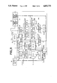
- FIG. 11 is a detailed block diagram of a path of the displacement estimating device according to the invention.
- FIG. 12 shows a method for estimating interframe motion by assigning a field of vectors to a fictitious frame
- FIG. 13 is a flow chart illustrating the functioning of the motion estimating method corresponding to the illustration of FIG. 12,
- FIGS. 14A, 14B and 14C show the direction in which the estimate of motion in a frame is propagated, as implementation by the method illustrated in FIG. 13,
- FIG. 15 illustrates the computation of the displaced frame difference and the luminance gradient in an example of a fictitious frame
- FIG. 16 shows the zone in which is located the end of the motion vector for a present pel (IX, IY, Tj) of a fictitious frame in a real frame
- FIG. 17 shows a general organization of the motion estimating device corresponding to the method shown in FIGS. 12 to 16,
- FIG. 18 shows a displacement vector estimating device for the implementation of the method illustrated in FIGS 12 to 16,
- FIGS 19A and 19B show an example of the memorizing of displacement vectors for prediction, in an example of the use of fictitious frames, according to the scanning direction.
- FIG. 20 is a detailed block diagram of a displacement estimating device of FIG. 19.
- the method according to invention is based on the use of a displacement estimating algorithm of the type described in an article by A. N. NETRAVALI and J. D. ROBBINS, "Motion Compensated Television Coding", Part 1, in Bell System Technology, Vol. 58, pages 631 to 670, March 1979.
- the gradient algorithm developed in this article minimizes the mean square deviation of the local variations in luminance of each current pel of a television picture between the current pel and its homologous pel in the prior picture.
- z (x,y) designates the spatial coordinates of the current pel P(z,t), as a function of its position identified in the plane (x,y,) of the picture;
- I(z,t) is the luminance of the present pel P(z,t) at the instant t;
- D i (z,t) is the estimated displacement at the pel P(z,t) at the iteration i and DFD(z,D) designates the displaced frame, this difference verifying the relationship:
- T designates the picture interval and grad I(z,t) designates the gradient vector of the present pel P(z,t).
- Epsilon designates the gain of the algorithm.
- epsilon is defined by the relationship:
- the method of the invention uses the existing frame differences between two successive pictures IMS t-1 and IMS t in a sequence of pictures, IMS t designating the picture at the instant t and IMS t-1 designating the prior picture, with the time unit considered being the picture interval.
- the method is conducted in several steps which are shown schematically in the flow chart of FIG. 1. In a first step, shown at 1 in FIG. 1, each present or current picture IMS is analyzed on a pel-by-pel basis by scanning each line.
- step 4 of the method is performed. This step consists in choosing a displacement in the causal neighborhood of the current pel P(z,p). If, on the contrary, the value of the gradient found in step 3 is above the threshold Sg, the processing operations indicated in step 5 are performed, to estimate four new displacements from four initial values of displacement in the causal neighbourhood of the current pel. At the end of step 5, the method proceeds to step 6 where a displacement is chosen from among the four displacements estimated in step 5. The method thus proceeds by successive iterations: each ending of the execution of steps 4 or 6 causes the initialization of the following pel (step 7) and the displacements are recorded in the step 8.
- the estimated displacement is limited in the picture, in lines and columns, to a rectangle of coordinates ⁇ DX MAX and ⁇ DY MAX with respect to the present pel.
- the zone for estimating motion in the present picture is limited to DX MAX and DY MAX (FIG. 2).
- the search for the displaced pel is made throughout the prior picture.
- the picture consists of two interlaced frames, frame 1 and frame 2.
- frame 1 is taken at the instant t, and frame 2 at the instant t+T/2, T representing the picture interval.
- the motion is estimated according to an inter-picture mode, i.e. by comparing the frames 1 and the frames 2 of two successive pictures. If designates the number of lines included in a picture, the lines of frame 1 are numbered 1 to T/2 and those of the frame 2 are numbered T/2+1 to .
- FIG. 2 A representation of the corresponding estimation zones is shown in FIG. 2 in the form of a triangle for each of the frames 1 and 2 respectively of the present picture IMS(t) and the prior picture IMS(t-T).
- DC and FC respectively designate the first and last useful column of the picture
- DL 1 and FL 1 respectively designate the first and last useful lines of the frame number 1
- DL 2 and FL 2 respectively designate the first and last useful lines of the frame number 2.
- the estimation zone Z 1 of the frame 1 is defined by the relationship:
- the displacements which are estimated in the closest causal neighborhood of the current pel serve to initialize the motion estimating algorithm.
- This causal neighborhood contains four displacements which are used to initialize four estimates of motion in parallel.
- the estimate is propagated, in the method, along the normal scanning direction for television pictures. However, to avoid favoring one propagation direction in the picture, for example left to right, the scanning direction is reversed alternately at every other line.
- This scanning in odd-numbered and even-numbered alternating lines is shown in FIG. 3a and the initial values D 0 A , D 0 B , D 0 C and D 0 D for the odd-numbered lines and the even-numbered lines are respectively shown in FIGS. 3A and 3B.
- the gradient in the present picture is computed at the present pel P(z,t) according to the scanning of the present line. Since this computation respects causality, it differs according to the scanning direction. For an odd-numbered line, the gradient verifies the relationship:
- the threshold Sg is the threshold used on the modulus of the present gradient.
- ID and FD respectively designate the whole and fractional parts of the displacements.
- the unit of displacement in X is formed by the interval between two pels on the same line and the unit of displacement in Y consists of the interval between two lines in the same frame.
- the gradients they are calculated according to the known method described in the article by S. SABRI, "Movement Compensated Inter-Frame Prediction for NTSC Color Television Signals" in IEEE TRANS, Vol. 32, No. 8, August 1984. representation of these computations in the form of a graph is given in FIG. 5 which shows displacements in the prior picture IMS (t-1).
- the luminance I B of the present pel displaced in the prior picture is obtained by the bilinear interpolation of the luminances I n of the neighboring pels. This implies the following relationship with the notations of FIG. 5:
- the horizontal gradient is:
- the vertical gradient is:
- tests for limiting the correcting terms expressed in units of displacement may be defined, if necessary, as follows:
- the search zone in the IMS (t-1) frame for a present pel P(z,t) is defined in a rectangle with a dimension of 30 ⁇ 10 as shown in FIG. 6.
- the four estimates of displacement are made in parallel, using the four initial values D 0 A , D 0 B , D 0 C and D 0 D .
- the pel is considered to be divergent but, all the same, it is assigned a displacement, namely that displacement among D iMAX , D iMAX , and D iMAX , D iMAX which gives the lowest absolute value of DFD.
- a displacement is chosen in the causal neighbourhood of the present pel P(z,t) and no iteration is done (i-0).
- the criterion for decision then lies in choosing that displacement which, among the values D 0 A , D 0 B , D 0 C and D 0 D , gives the lowest absolute value of the displaced frame difference DFD(z,D 0 ). In the event of equality, the choice is made in the order D 0 A , D 0 B , D 0 C and D 0 D (steps 9 to 13 of FIG. 7). However, if the displaced frame difference of the chosen displacements is not below or equal to the threshold S (step 16), the convergence test threshold, the displacement takes the value 0 (step 17).
- the displacement retained is the first one that gives a
- each iteration I(0 ⁇ i ⁇ i MAX ) is associated a displacement D i , a displaced frame difference DFD and an iteration number i.
- FIG. 8 An embodiment of a device corresponding to the method mentioned is shown in FIG. 8. It consists, for example, of line memories 18, a picture memory 19, a device 20 to compute the modulus of the present gradient, a switching device 21 as well as decision elements 22 and 22a and a displacement estimating element 23.
- the device for computing the present gradient modulus receives its data from all the line memories 18 and gives the result of the computations to the displacement estimating device 23 and the switching device 21.
- the displacement estimating device also has two inputs which are connected, firstly, to the output of all the line memories 18 and, secondly, to the output of the picture memory 19.
- the line memory 18 acts as a buffer to the picture memory 19 to store the refresh data for the picture memory 19 pending a stage when the analyzed pels will be outside the exploration window.
- a line memory with a pel-storing capacity corresponding to five successive lines would appear to be sufficient.
- the computations are done at the pel frequency, at the rate of the clock pulses, H 1 and H k , given by a line clock (not shown).
- the device 20 determines the present line number 1 and, depending on the parity of the present line number 1, it determines the current pel column number k.
- the device 20 which then has the coordinates (k,1) of the present pel available to it, computes the modulus of the present gradient.
- the switching device 21 compares the result of the computation given by the device 20 with a reference threshold Sg and, according to the algorithm shown in FIG. 1, validates its input 1 or 2.
- the input 1 is chosen if
- the decision elements 22 and 22a have the functions described in the flow chart of FIG. 7 and can be made in a known way, either with a microprocessor-type microprogrammed structure or with a wired logic circuit made up, in a known way, of comparator circuits.
- the displacement estimating device shown in FIG. 9 consists of an initializing block 24 consisting of registers 25 and 26 and a computing set 23 made up of the elements 27 to 46.
- This computing unit 23 gives the displacement data D i A , D i B , D i C , D i D to the decision element 22.
- the input 2 of the switching device 21 (FIG. 8) is connected to the decision element 22.
- the initializing block 24 is used to initialize the displacement computing algorithm.
- the block 24 has a first register 25 and a second register 26.
- registers consist of two distinct parts, one to store binary words representing the displacement mode in x or in y, respectively called MDX and MDY and the other to act as a buffer memory for the words representing the displacement modes MTDX and MTDY computed by the decision element 22.
- MTDX and MTDY are used as intermediaries before overlaying the words MDX and MDY, corresponding to the displacements D(k-1,1-1), for proceeding to the analysis of the following pel (k+1,1) as shown in FIG. 10A. They also serve as intermediaries before overlaying the words MDX and MDY corresponding to 048537757.002 the displacements D(k+1,1--1) for proceeding to the analysis of the following pel (k-1,1) as shown in FIG. 10B.
- the estimated displacement D(FC,1) is automatically put in the words (MTDX, MTDY) and, furthermore, in the words (MDX, MDY) corresponding to the displacements D(FC,1) and D(FC+1,1).
- the estimated displacement D(DC,1) is automatically put in the words (MTDX, MTDY) and, furthermore, in the words (MTX, MDY) corresponding to the displacements D(DC,1) and D(DC-1,1).
- the displacement estimation computing device consisting of the elements 27 to 46, does four parallel displacement computations from four initial values D O A , D O B , D O C , D O D contained in the initializing block 24, when the spatial gradient of the present picture is above the threshold Sg defined above.
- the data D O A , D O B , D O C , and D O D are respectively applied to the first inputs of the switching circuits 27, 32, 37 and 42, the outputs of which are connected to convergence-testing and correcting-term computing blocks respectively marked (28, 29), (33, 34), (38, 39), and (43, 44).
- the results of the convergence tests and of the computation of the correcting terms are applied to the inputs of switching devices, respectively marked 30, 35, 40 and 45 which then direct them either to respective inputs of the decision element 22 or to devices for computing new displacements, respectively marked 31, 36, 41 and 46, when the solution of the earlier-described algorithm deviates for i lower than i MAX .
- the new displacements given by the computing devices 31, 36, 41 and 46 are respectively applied to the second inputs of switching devices 27, 32, 37 and 42.
- the convergence-testing block 28 includes, firstly, an interpolation circuit 47, coupled to a device 48 for computing the absolute value of the displaced frame difference
- the interpolation circuit 47 which may, if necessary, consist of a programmable read-only memory, is also coupled to the picture memory 19.
- the correcting-terms computing block 29 has a computing device 53 to compute the above-described value epsilon, coupled to an increment-computing device 54 and a correction values computing device 55 as well as comparator circuits 56 and 57.
- the new displacements computing block 31 has subtracting circuits 58 and 59, both coupled to a comparator circuit 60.
- the convergence-testing block 28 and the correcting-term computing block 29 are coupled, as in FIG. 9, by the switch 30.
- the input of the switch is directly coupled to the output of the computing device 52 and to the output of the computing device 48, through switches 49 and 50.
- the initializing block 24 is coupled to the convergence-testing block 28 through the switch 27. This switch connects the initializing block 24, firstly, to a first input of the interpolation circuit 47 and, secondly, to a first input of the computing device 51.
- the second input of the switch 27 is also coupled to the output of the new displacement computing block 31, which consists of the comparator circuit 60.
- the displacement estimating device works as follows. For each of the present pels of the picutre, the switch 27 transmits an initial value D O , found in the register 24, to the interpolation circuit 47 and the gradient-computing device 51.
- the value D O initializes the estimation.
- a bilinear interpolation on the value D 0 is computed by the interpolation circuit 47 to determine the luminance of the present pel displaced in the prior picture I(z-DO,t-1).
- and its absolute value are computed by the computing device 48 using data on the luminance of the present pel.
- the switch 49 sends the value computed by the computing device 48 to the decision element 22 when the value obtained is smaller than or equal to the above-defined threshold S.
- the displacement D O and absolute value of the displaced frame difference DFD(D O ) are applied to the inputs of the decision element. Otherwise, the result given by the computing device 48 is applied to the input of the switch 50 and then to the input of the decision element 22 when the iteration value i is equal to the maximum iteration value i MAX . On the contrary, when the iteration value i is smaller than the maximum value, the result is applied to the inputs of the correction computing block 29 through the switch 30.
- the switch 30 sends the result obtained either towards the decision element 22, if the value of G2 obtained is smaller than or equal to a coefficient value of 0.125 for example, or to the computing block for correcting terms of new displacements 29 and 31.
- the iteration value i is increased by one unit by the increment computing device 54 and is reset at zero for the analysis of the following present pel.
- the terms (TC) x and (TC) y for correction in X and Y are computed by the circuit 55.
- the values (TC) x and (TC) y obtained at the outputs of the computing device 55, verify the relationships:
- the values (TC) x and (TC) y obtained are respectively applied to the inputs of the comparators 56 and 57 to be limited (barring plus or minus signs) to maximum and minimum values.
- the minimum values of (TC) x and (TC) y are the same and are fixed at 1/16.
- the maximum value of (TC) x is fixed so as to be equal to 3 and the maximum value of (TC) y is fixed so as to be equal to 2.
- (TC) x and (TC) y obtained are added to the displacement values D x O and D O y by the circuits 58 and 59, and the results obtaind D 1 x and D 1 y , which correspond to the estimated displacements, are again limited by the comparator circuit 60 before being applied to the second input of the switch 27.
- the switch 27 applies the estimated displacements D 1 x and D 1 y to the circuits 47, 51, 58 or 59.
- a displacement is chosen for the present pel and is written in the MTDX and MTDY buffer memory 24. i is reset at zero and the switch 27 returns to its starting position, and the computations described above are started again to estimate the displacement of the new present pel.
- the luminance values of the pels of the missing frames, in a sequence of pictures representing one and the same scene, cannot be taken into account to determine the motion of the objects of the scene.
- An alternative embodiment of the method according to the invention will remove this disadvantage, by enabling the determination of a field of motion between two generally successive frames in a sequence of pictures in the form of a field of vectors assigned to a fictitious frame generally located between two parent frames.
- the field of motion consists of a set of vectors. Each vector passes through a pel of the fictitious frame, and has its endpoints on the two parent frames on either side of it.
- the parent frames are designated by the instants Ta and Tb at which they were shot.
- the fictitious frame is located at an intermediate instant t j between the instants Ta and Tb.
- the purpose here is to give a displacement vector to each pel of the fictitious frame considered at the instant T j (the luminance of each pel being unknown in principle) from the luminance field of the frames of the instants Ta and Tb.
- the instant T j it will also be possible to consider the instant T j as being also located outside the interval (Ta, Tb).
- the method according to the invention is similar to the method described above with the difference, however, that it enables an estimation of motion between two frames at instants Ta or Tb for the pels of the fictitious frame Tj.
- the complexities of the algorithm and of the resulting estimating device are of the same magnitude.
- the estimation of motion is computed from the luminance LO of the pels of the frames of the instants Ta and Tb.
- the estimated motion for each pel takes the shape of a vector D with two components, a horizontal component DX and a vertical component DY.
- Z is a vector designating the spatial coordinates of the present pel P(Z, Tj) for which the motion vector D(Z, Tj) is estimated
- Di(Z,Tj) is the estimated displacement vector at the pel P(Z, Tj) at the iteration i,
- DFD(Z, Di-1) designates the temporal difference in luminance in the displacement direction Di-1, still called “displaced frame difference” and computed between Ta and Tb according to the relationship;
- grad L(Z, Di-1) is a vector designating the spatial gradient, which is the half sum of the spatial gradients at the endpoints of Di-1, on Ta and Tb. Its value is defined by:
- the equation (24) above is hardly different. It differs, however, in the computing of the functions DFD and grad L because the motion vector pivots around the pel (Z, Tj) and, consequently, its ends at the instants Ta and Tb frames vary while, in the method described earlier, the vector pivoted by one end around the pel P(Z, Tb) and had its other end free on the instant Ta frame.
- the result of this is that the advantages given by the estimating unit used by the method described earlier are preserved.
- the strategies that continue to be meaningful in the present estimating unit are preserved. These are, in particular:
- the decision element relating to the choice of a displacement among four estimated displacements.
- the method which consists in comparing the gradient of the luminance of the present pel to a threshold, and in making a distinction between two procedures depending on whether this gradient is (strictly) greater or smaller than this threshold is eliminated.
- All the pels of the fictitious frame Tj therefore follow the same procedure for estimating the motion vector according to four recurrences calculated in parallel.
- the estimate is calculated between two frames Ta and Tb, which may have the same parity or different parities, and for a frame Tj which may also be even-numbered or odd-numbered.
- a corrective vector designated by dZa or dZb, is introduced into the computing of the functions DFD and grad L.
- dZa depends on the relative parity of Ta and Tj
- dZb depends on the relative parity of Tb and Tj.
- the various equations presented above remain unchanged.
- the method of the invention uses the existing interframe differences between two instants Ta and Tb frame which may directly or indirectly follow one another in a sequence of pictures.
- each pel of the fictitious frame of an instant Tj is rectilinear between two frames at instants Ta and Tb, and each object element of the fictitious frame at the instant Tj (pel luminance) is also assumed to be present in the instants Ta and Tb frames.
- the method occurs in several steps, a schematic depiction of which is given in the flow chart of FIG. 13.
- a first step shown at 61 in FIG. 13
- each pel of the present frame is taken into consideration through a line scanning of all the pels of the frame.
- the processing operations shown in the step 62 are performed to estimate four displacement values from four initial displacement values in the causal neighbourhood of the present pel.
- step 62 the method goes to the execution of the step 63 and a displacement is chosen from among the four displacements estimated in the step 62.
- the method thus takes place by successive iterations, with each end of execution of the step 63 causing the initialization of the following pel (step 64), and the displacements are recorded at the step 65.
- the displacement between the instants Ta and Tb frames is limited to values of ⁇ DXmax in horizontal displacement and ⁇ DYmax in vertical displacement.
- each motion vector, passing through each pel (PZTj) of the present frame are located at instants Ta and Tb frames inside a rectangle which is respectively centered on the pels (Z, Ta) and (Z, Tb) with respective dimensions of 2x((Tj-Ta)/(Tb-Ta)) ⁇ (Dxmax, DYmax) and 2x((Tb-Tj)/(Tb-Ta))x(Dxmax,DYmax), these latter terms depending respectively on the distance from Tj and Ta and Tj to Tb, relatively with respect to the instants Ta and Tb.
- all the pels on the frame Tj for which a displacement vector is estimated are included inside another rectangle, the center of which coincides with the center of the frame, and the dimensions of which are smaller than the dimensions of the frame of DXmax+2 columns and DYmax+2 lines (+2 is imposed by the computation of the spatial gradient).
- a test may be added to ascertain that the endpoints of the vector are actually located on the instants Ta and Tb frames.
- the unit of displacement in X is formed by the interval between two pels on the same line and the unit of displacement in Y consists of the interval between two lines in the same frame.
- the gradients are calculated in the above-described way, and illustrated by FIG. 15 which represents a part of the instant Ta frame, and a displacement vector for which the endpoint on the instant Ta frame has the coordinates (Z-DA, Ta) and luminance LA.
- the luminance LB of its endpoint in the instant Tb frame and the displacement vector DB at this point are calculated in the same way.
- the luminance LA of the present pel displaced in the instant Ta frame is obtained by the bilinear interpolation of the luminances Ln of the neighbouring pels. This implies the following relationship with the notations of FIG. 15:
- the spatial luminance gradient G at this pel is calculated as follows: If FDX is smaller than 0.2 and if FDY is smaller than 0.2 then:
- FDX and FDY are different from zero and the maximum precision on the gradient is 0.5
- the search zone in the instants Ta and Tb frames for a present pel P(Z,Tj) is then defined by a rectangle on each frame Ta and Tb having the following respective dimensions:
- the four displacement estimations are done in parallel from the four initial values D O A D O B D O C and D O D .
- the pel If no displacement value gives a DFD value smaller than or equal to S, the pel is considered to be divergent but, all the same, it has a displacement assigned to it, namely that displacement, from among D iMAX , D iMAX , D iMAX and D iMAX , which gives the absolute value of the smallest displaced frame difference DFD.
- the method gives four values of DFD (Di) which are compared with the threshold S.
- the displacement retained is the first which gives the DFD value smaller than or equal to the threshold S. If several displacements are obtained at the same iteration, the one that gives the smallest displaced frame difference DFD is chosen. If there is again equality in the value of DFD, an arbitrary choice is made in the following order:
- the decision is taken on the smallest number of iterations and then on the minimum displaced frame difference DFD and then, as the case may be, according to an arbitrary choice.
- FIGS. 8, 9 and 11 are shown in FIGS. 17, 18 and 20, with similar elements in these figures bearing the same references.
- the device shown in FIG. 17 comprises a set of line memories 18, a frame memory 19, a scanning direction determining device 20, a displacement estimating element 23, a decision element 22 and a motion vector initializing element 24.
- the displacement estimating device has two inputs which are connected, firstly, to the output of the frame memory 19, and secondly, to the output of the line memory 18.
- Each of the line memories 18 acts as a buffer for the frame memory 19 to store refresh data for this frame memory 19 pending the stage when the analyzed pels are outside the exploration window.
- an exploration window of the type shown in FIG. 16 occupying, for example, a space of 8 lines, a line memory with a pel-storing capacity corresponding to 10 successive lines would appear to be quite sufficient.
- the computations are done at the pel frequency, at the rate of the clock pulses, H1 and Hk, given by a line clock (not shown).
- the scanning direction determining device 20 determines the present line number 1 and, depending on the parity of this present line number 1, it determines the present pel column number k. It thus has the coordinates (k,1) of the present pel available to it.
- the decision element 22 has the functions described in FIG. 18 and can be made in a known way, either with a microprocessor-type microprogrammed structure or with a wired logic circuit obtained, in a known way, through comparator circuits.
- the displacement estimating device shown in FIG. 18 consists, in a manner similar to the device shown in FIG. 9, of an initializing block 24 consisting of registers 25 and 26 and a computing unit 23 made up of the elements 27 to 46.
- the computing unit 23 gives the displacement data D i A , D i B , D i C , D i D to the decision element 22.
- the initializing block 24 has a first register 25 and a second register 26. These registers consist of two distinct parts, on representing the displacement mode in x or in y, respectively called MDX and MDY, and the other to act as a buffer memory for the displacement modes MTDX and MTDY computed by the decision element 22.
- MTDX and MTDY are used as intermediaries before overlaying the words MDX and MDY contained in the registers 25 and 26, corresponding to the displacements D(k-1,1--1), for proceeding to the analysis of the following pel (k+1,1) as shown in FIG. 19A. They also serve as intermediaries before overlaying the words MDX and MDY, contained in the registers 25 and 26, corresponding to the displacements D(k+1,1--1) for proceeding to the analysis of the following pel (k-1,1) as shown in FIG. 19B.
- D(FC+1, L+1) (D(FC,L)+D(FC-1,L)+D(FC-2,L)+D(FC-3,L2))/4.
- This displacement is registered in the word (MTDX, MTDY). It constitutes the initial displacement D O A of the next displacement to be estimated D(FC, L+1).
- D(DC+1, L+1) (D(DC,L)+D(DC+1,L)+D(DC+2,L)+D(DC+3,L2))/4.
- the displacement estimation computing device of FIG. 18, consisting of the elements 27 to 46, does four parallel displacement computations from four initial values D O A , D O B , D O C , D O D contained in the initializing block 24.
- the four initial values are respectively applied to the first inputs of switching circuits 27, 32, 37 and 42, the outputs of which are connected to convergence-testing and correcting-term computing blocks respectively marked (28, 29), (33, 34), (38, 39), and (43, 44).
- the results of the convergence tests and of the computation of the correcting terms are applied to the inputs of switching devices, respectively marked 30, 35, 40 and 45 which then direct them either to respective inputs of the decision element 22 or to devices for computing new displacements, respectively marked 31, 36, 41 and 46, when the solution of the earlier-described algorithm deviates for i lower than i max.
- the new displacements given by the computing devices 31, 36, 41 and 46 are respectively applied to the second inputs of switching devices 27, 32, 37 and 42.
- the convergence-testing block 28 of FIG. 20 includes, firstly, two interpolation circuits 47 and 47a, coupled to a device 48 for computing the absolute value of the displaced frame difference DFD, this device 48 being coupled to the decision element 22 through switches 49, 50 and, secondly, two gradient-computing devices 51 and 51b, coupled to a device 52 for computing the displaced mean gradients.
- This device 52 is itself connected to a device 52a for computing the sum of the squares of the displaced mean gradients.
- the interpolation circuit 47 which may consist of a programmable read-only memory, is also coupled to the frame memory 19.
- the interpolation circuit 47a which may also consist of a read-only memory, is connected to the lines memory 18.
- the correcting-terms computing block 29 has a computing device 53 to compute the above-described correction value epsilon, coupled to an increment-computing device 54 and a correction values computing device 55 as well as comparator circuits 56 and 57.
- the new displacements computing block 31 had subtracting circuits 58 and 59, both coupled to a comparator circuit 60.
- the convergence-testing block 28 and the correcting-term computing block 29 are coupled, as in FIG. 18, by the switch 30.
- the input of the switch is directly coupled to the output of the computing device 52 and to the output of the computing device 48, through switches 49 and 50.
- the initializing block 24 is coupled to the convergence-testing block 28 through the switch 27.
- This switch connects the initializing block 24, firstly, to a first input of the interpolation circuit 47s 47 and 47a and, secondly, to a first input of the computing devices 51 and 51b.
- the second input of the switch 27 is also coupled to the output of the new displacement computing block 31, which consists of the comparator circuit 60.
- the displacement estimating device works as follows. For each of the present pels of the picture, the switch 27 transmits an initial displacement value Do, found in the register 24, to the interpolation circuits 47 and 47a and the gradient-computing devices 51 and 51a. The value Do initializes the estimation.
- a bilinear interpolation on the value Do is computed, firstly by the interpolation circuit 47 to determine the luminance L(Z-D o x(Tj-Ta)/(Tb,Ta), of the present pel (Z,Tj) displaced in the prior instant Ta trame with the value Do ⁇ (Tj-Ta)/(Tb-Ta) and, secondly, by the interpolation circuit 47a to determine the luminance L(Z+Do(Tb-Tj)/(Tb-Ta),Tb) of the same present pel which displaced, this time, in the following frame Tb with the value Do x(Tb-Tj)/(Tb-Ta).
- the displaced frame difference DFD(Z,Do) and its absolute value are computed by the computing device 48.
- the switch 49 sends the value computed by the computing device 48 to the decision element 22 when the value obtained is smaller than or equal to the above-defined threshold S.
- the displacement Do and absolute value of the displaced frame difference DFD(Do) are applied to the inputs of the decision element. Otherwise, the result given by the computing device 48 is applied to the input of the switch 50 and then to the input of the decision element 22 when the iteration value i is equal to the maximum iteration value i max. On the contrary, when the iteration value i is smaller than the maximum value, the result given by the computing device 48 is applied to the inputs of the correction computing block 29 through the switch 30.
- the relative parities of the instants Ta and Tj frames are taken into account in the circuits 47 and 51 and the relative parities of the instants Tb and Tj are taken into account in the circuits 47a and 51a.
- the switch 30 sends the result obtained either towards the decision element 22, if the value of G2 obtained is smaller than or equal to a coefficient value of 0.125 for example, or to the computing block for correcting terms of new displacements 29 and 31.
- the iteration value i is increased by one unit by the increment computing device 54 and is reset at zero for the analysis of the following present pel.
- the terms (TC) x and (TC) y for correction in X and Y are computed by the circuit 55.
- the values (TC) x and (TC) y obtained at the outputs of the computing device 55, verify the relationships:
- the values (TC) x and (TC) y obtained are respectively applied to the inputs of the comparators 56 and 57 to be limited (barring plus or minus signs) to maximum and minimum values.
- the minimum values of (TC) x and (TC) y are the same and are fixed at 1/16.
- the maximum value of (TC) x is fixed so as to be equal to 3 and the maximum value of (TC) y is fixed so as to be equal to 2.
- (TC) x and (TC) y obtained are added to the displacement values D o x and D o y by the circuits 58 and 59, and the results obtained D 1 x and D 1 y , which correspond to the estimated displacements, are again limited by the comparator circuit 60 before being applied to the second input of the switch 27.
- the switch 27 applies the estimated displacements D 1 x and D 1 y to the circuits 47, 51, 58 or 59.
- a displacement is chosen for the present pel and is written in the zones MTDX and MTDY of the buffer memory 24.
- the iteration value i is reset at zero, the switch 27 returns to its starting position, and the computations described above are started again to estimate the displacement of the new present pel.
Abstract
Description
D.sub.i (z,t)=D.sub.i-1 (z,t)-ε.DFD(z,D.sub.i-1).grad I(z-D.sub.i-1,t-T) (1)
DFD(z,D)=I(z,t)-I(z-D,t-T) (2)
ε=1/2.|grad I(z-D.sub.i-1,t-1|.sup.2(3)
|grad I(z-D.sub.i-1,t-1)|.sup.2 =
|grad I(z-D.sub.i-1,t-1)|.sup.2 =0, alors ε=0(5)
Z.sub.1 :{p(k,1)/Kε[DC+DX.sub.MAX, FC-DX.sub.MAX ] and
1ε[DL.sub.1 +DY.sub.MAX,FL.sub.1 -DY.sub.MAX ]}(6)
Z.sub.2 :{p(k,1)/Kε[DC+DX.sub.MAX, FC-DX.sub.MAX ]and
1ε[DL.sub.2 +DY.sub.MAX,FL.sub.2 -DY.sub.MAX ]} (7)
grad.sub.x =I(k,1)-I(k,-1,l); grad.sub.y =I(k,1)-I(k,l-1) (8)
grad.sub.x =I(k+1,l)-I(k,l); grad.sub.y =I(k,l)-I(k,l-1) (9)
Avec|grad I(z,t)|=√grad.sup.2.sub.X +grad.sup.2.sub.y (10)
D.sub.x =ID.sub.x +FD.sub.x and D.sub.y =ID.sub.y +FD.sub.y,
I.sub.B =I.sub.5.(1-FD.sub.x).(1-FD.sub.y)+I.sub.6.FD.sub.x.(1-FD.sub.y)
I.sub.x =(I.sub.5 -I.sub.6 +I.sub.2 -I.sub.1)/2 (12)
if FD.sub.x =0: I.sub.x =(I.sub.4 -I.sub.6 +I.sub.3 -I.sub.1)/4 (14)
I.sub.y =(I.sub.5 -I.sub.2) (15)
if FD.sub.y =0 I.sub.x =(I.sub.5 -I.sub.6) (16) I.sub.y =(I.sub.7 -I.sub.1 +I.sub.8 +I.sub.2)/4 (17)
I.sub.x =(I.sub.4 -I.sub.6 +I.sub.3 -I.sub.1)/4 (18)
I.sub.y =(I.sub.7 -I.sub.1 +I.sub.8 -I.sub.2)/4 (19)
D.sup.x.sub.i =D.sub.i-1.sup.x -(correcting term).sup.x (20).
D.sup.y.sub.i =D.sub.i-1.sup.x -(correcting term).sup.y (21)
(correcting term) .sup.x =DFD(z,D.sub.i-1).grad.sub.x I(z-D.sub.i-1,t-1).(22)
(correcting term) .sup.y =DFD(z,D.sub.i-1).grad.sub.y I(z-D.sub.i-1,t-1).(23)
(TC).sup.x =DFD(z,D.sub.i)×grad.sub.x (D.sub.i)×ε
and
(TC).sup.y =DFD(z,D.sub.i)×grad.sub.y (D.sub.i)×ε
Di(Z,Tj)=Di-1(Z,Tj)-TC (24)
with TC=(DFD(Z,Di-1).grad L(Z,Di-1))/2.(grad L(Z,Di-1)).sup.2
DFD(Z, Di-1)=L(B, Tb)-L(A, Ta)
with B=Z+((Tb-Tj)/(Tb-Ta))×Di-1
A=Z-((Tj-Ta)/(Tb-Ta))×Di-1
2 grad L(Z, Di-1)=grad L(A, Ta)+grad L(BTp).
DFD=L(B+dZb, Tb)-L(A+dZa, Ta) (25)
2×grad L(Z,Di-1)=grad L(B+dZb, Tb)-grad L(A+dZa, Ta) (26)
DA=((Tj-Ta)/(Tb-Ta))×D
DB=((Tb-Tj)/(Tb-Ta))×D
LA=I.sub.9.(1-FDX).(1-FDY)+I.sub.8.FDX.(1-FDY)+I.sub.4 (1-FDX).FDY+I.sub.5.FDX.FDY
GX=(I.sub.10 -I.sub.8)/2
GX=(I.sub.3 -I.sub.5)/2
GY=(I.sub.9 -I.sub.2)/2
GX=(I.sub.10 -I.sub.8 +I.sub.3 -I.sub.4)/4
GY=(I.sub.9 -I.sub.2)/2
GX=(I.sub.9 -I.sub.7)/2
GY=(I.sub.12 -I.sub.5)/2
GX=(I.sub.4 -I.sub.6)/2
GY=(I.sub.8 -I.sub.1)/2
GX=(I.sub.4 -I.sub.6)/4
GY=(I.sub.8 -I.sub.1)
GX=(I.sub.9 -I.sub.8)
GY=(I.sub.11 -I.sub.4 +I.sub.12 -I.sub.5)/4
GX=(I.sub.4 -I.sub.5)
GY=(I.sub.9 -I.sub.2 +I.sub.8 -I.sub.1)/4
GX=(I.sub.4 -I.sub.5 +I.sub.9 -I.sub.8 /2
GY=.(I.sub.9 -I.sub.4 +I.sub.8 -I.sub.5)/2
DFD (Z,D)=LP-LA
2×grad L(Z,D)=GA+GB
D.sup.x.sub.i =D.sub.i-1.sup.x -(correction term in x)
D.sub.i.sup.y =D.sub.i-1.sup.y -(correction term in y)
with epsilon=1/2x(gradL(Z,D.sub.i-1)).sup.2 (27)
and grad L(Z,Di-1).sup.2 =grad.sup.2.sub.x L(Z,Di-1)+
DXmax x((Tj-Ta)/(Tb-Ta)),DYmax x((Tj-Ta)/(Tb-Ta)) and
DXmax x((Tb-Tj)/(Tb-Ta)),DYmax x((Tb-Tj)/(Tb-Ta))
D.sub.i.sup.A D.sub.i.sup.B D.sub.i.sup.C and D.sub.i.sup.D.
2×gradX=gradXa+gradXp
2×gradY=gradYa+gradYp
(TC).sup.x =DFD(z,Di)x grad.sub.x (Di)x epsilon
and
(TC).sup.y =DFD(Z,Di)x grad.sub.y (Di)x epsilon.
Claims (24)
Di(Z,Tj)=Di-1(Z,Tj)-(DFD(Z,Di-1).grad
Applications Claiming Priority (4)
| Application Number | Priority Date | Filing Date | Title |
|---|---|---|---|
| FR8703991 | 1987-03-23 | ||
| FR8703991A FR2613164B1 (en) | 1987-03-23 | 1987-03-23 | METHOD AND DEVICE FOR ESTIMATING MOTION IN A SEQUENCE OF MOVED IMAGES |
| FR878717289A FR2624682B2 (en) | 1987-03-23 | 1987-12-11 | METHOD AND DEVICE FOR ESTIMATING MOTION IN A SEQUENCE OF MOVED IMAGES |
| FR8717289 | 1987-12-11 |
Publications (1)
| Publication Number | Publication Date |
|---|---|
| US4853775A true US4853775A (en) | 1989-08-01 |
Family
ID=26225861
Family Applications (1)
| Application Number | Title | Priority Date | Filing Date |
|---|---|---|---|
| US07/171,835 Expired - Lifetime US4853775A (en) | 1987-03-23 | 1988-03-22 | Method and device to estimate motion in a sequence of moving pictures |
Country Status (6)
| Country | Link |
|---|---|
| US (1) | US4853775A (en) |
| EP (1) | EP0286483B1 (en) |
| JP (1) | JP2803818B2 (en) |
| CA (1) | CA1329649C (en) |
| DE (1) | DE3870969D1 (en) |
| FR (1) | FR2624682B2 (en) |
Cited By (45)
| Publication number | Priority date | Publication date | Assignee | Title |
|---|---|---|---|---|
| US4969036A (en) * | 1989-03-31 | 1990-11-06 | Bir Bhanu | System for computing the self-motion of moving images devices |
| EP0415491A1 (en) | 1989-08-29 | 1991-03-06 | Koninklijke Philips Electronics N.V. | Motion estimation |
| US5008744A (en) * | 1988-09-05 | 1991-04-16 | U.S. Philips Corporation | Method and apparatus for picture motion measurement using picture correlation as a function of displacement |
| US5028996A (en) * | 1989-06-26 | 1991-07-02 | Matsushita Electric Industrial Co., Ltd. | Picture coding method |
| US5043807A (en) * | 1989-05-23 | 1991-08-27 | Zenith Electronics Corporation | Three dimensional composite video motion detection |
| US5045929A (en) * | 1989-05-13 | 1991-09-03 | Zenith Electronics Corporation | Three dimensional luma/chroma separation and vertical detail generation |
| US5060064A (en) * | 1988-04-29 | 1991-10-22 | U.S. Philips Corporation | Arrangement for interpolation images by motion estimation and compensation and a television standard converter system comprising such an arrangement |
| US5070403A (en) * | 1989-04-21 | 1991-12-03 | Sony Corporation | Video signal interpolation |
| US5089887A (en) * | 1988-09-23 | 1992-02-18 | Thomson Consumer Electronics | Method and device for the estimation of motion in a sequence of moving images |
| EP0472806A2 (en) * | 1990-08-31 | 1992-03-04 | Director-General Of The Agency Of Industrial Science And Technology, | Method for detecting change points in motion picture images |
| US5105271A (en) * | 1989-09-29 | 1992-04-14 | Victor Company Of Japan, Ltd. | Motion picture data coding/decoding system having motion vector coding unit and decoding unit |
| US5128769A (en) * | 1989-07-18 | 1992-07-07 | Fuji Photo Film Co., Ltd. | Method and apparatus for controlling exposure of video camera |
| US5142360A (en) * | 1990-03-06 | 1992-08-25 | Victor Company Of Japan, Ltd. | Motion vector detection circuit used in hierarchical processing of moving picture signal |
| US5216501A (en) * | 1989-02-13 | 1993-06-01 | Matsushita Electric Industrial Co., Ltd. | Apparatus for detecting moving and unmoving regions in a moving image using a calculator |
| US5257102A (en) * | 1991-02-04 | 1993-10-26 | Sony United Kingdom Limited | Television standards converters using motion vectors corresponding to correlation of horizontal and vertical pixel offsets |
| US5353061A (en) * | 1992-10-08 | 1994-10-04 | International Business Machines Corporation | System and method for frame-differencing video compression/decompression using perceptually-constant information and image analysis |
| US5475446A (en) * | 1992-03-09 | 1995-12-12 | Matsushita Electric Industrial Co., Ltd. | Picture signal motion detector employing partial decimation of pixel blocks |
| US5539454A (en) * | 1995-02-06 | 1996-07-23 | The United States Of America As Represented By The Administrator, National Aeronautics And Space Administration | Video event trigger and tracking system using fuzzy comparators |
| EP0731612A1 (en) * | 1995-03-09 | 1996-09-11 | Daewoo Electronics Co., Ltd | Apparatus for encoding a video signal using a search grids for motion estiamtion and compensation |
| GB2311184A (en) * | 1996-03-13 | 1997-09-17 | Innovision Plc | Motion vector field error estimation |
| US5726713A (en) * | 1995-12-22 | 1998-03-10 | Siemens Aktiengesellschaft | Method of computer assisted motion estimation for picture elements of chronologically successive images of a video sequence |
| US5809174A (en) * | 1993-04-13 | 1998-09-15 | C-Cube Microsystems | Decompression processor for video applications |
| US6037986A (en) * | 1996-07-16 | 2000-03-14 | Divicom Inc. | Video preprocessing method and apparatus with selective filtering based on motion detection |
| US6097832A (en) * | 1991-11-27 | 2000-08-01 | Thomson Consumer Electronics | Method of estimation and of hierarchised coding of the motion of image sequences |
| US6160901A (en) * | 1997-02-28 | 2000-12-12 | Mitsubishi Denki Kabushiki Kaisha | Processing device and method for determining direction of motion of an image |
| US6381285B1 (en) | 1996-03-13 | 2002-04-30 | Leitch Europe Limited | Gradient based motion estimation |
| US6556625B2 (en) * | 1996-09-20 | 2003-04-29 | At&T Corp. | Video coder providing implicit coefficient prediction and scan adaptation for image coding and intra coding of video |
| CN1108061C (en) * | 1995-03-20 | 2003-05-07 | 大宇电子株式会社 | Apparatus for encoding vided signal using search grid |
| US20040062440A1 (en) * | 2002-10-01 | 2004-04-01 | International Business Machines Corporation | Sprite recognition in animated sequences |
| US6842483B1 (en) | 2000-09-11 | 2005-01-11 | The Hong Kong University Of Science And Technology | Device, method and digital video encoder for block-matching motion estimation |
| US6996175B1 (en) | 1998-12-07 | 2006-02-07 | Koninklijke Philips Electronics N.V. | Motion vector estimation |
| US7519229B2 (en) | 2004-03-30 | 2009-04-14 | Apple, Inc. | Video coding system providing separate coding chains for dynamically selected small-size or full-size playback |
| DE102007051174A1 (en) | 2007-10-25 | 2009-04-30 | Micronas Gmbh | Method for motion estimation in image processing |
| DE102007051175A1 (en) | 2007-10-25 | 2009-04-30 | Micronas Gmbh | Method for motion estimation in image processing |
| US20090167959A1 (en) * | 2005-09-09 | 2009-07-02 | Sony Corporation | Image processing device and method, program, and recording medium |
| EP2105883A1 (en) | 2008-03-18 | 2009-09-30 | Trident Microsystems (Far East) Ltd. | Method for testing a movement vector |
| DE102008014790A1 (en) | 2008-03-18 | 2009-10-01 | Micronas Gmbh | Motion vector testing method for image processing, involves determining primary and secondary image blocks in primary and secondary image sections, respectively, using motion vector, and comparing contents of image blocks |
| US20090279741A1 (en) * | 2008-05-06 | 2009-11-12 | Honeywell | Method and apparatus for vision based motion determination |
| DE102008036279A1 (en) | 2008-08-04 | 2010-03-04 | Trident Microsystems (Far East) Ltd. | Method for determining movement vector at image block, involves preparing set of test vectors, and determining distance measurement of each test vectors by using forward estimation or reverse estimation |
| US20110075739A1 (en) * | 1996-09-20 | 2011-03-31 | At&T Intellectual Property Ii, L.P. | Video Coder Providing Implicit Coefficient Prediction and Scan Adaptation for Image Coding and Intra Coding of Video |
| US8254629B1 (en) * | 2008-08-26 | 2012-08-28 | Adobe Systems Incorporated | Methods and apparatus for measuring image stability in a video |
| US8582656B2 (en) | 2007-04-13 | 2013-11-12 | Apple Inc. | Method and system for video encoding and decoding |
| US8619874B2 (en) | 2007-04-13 | 2013-12-31 | Apple Inc. | Method and system for video encoding and decoding |
| CN113774177A (en) * | 2021-09-13 | 2021-12-10 | 内蒙古科技大学 | Method and device for detecting displacement times of bellows of blast furnace distributor |
| CN117251818A (en) * | 2023-11-17 | 2023-12-19 | 上海伯镭智能科技有限公司 | Data management method for safe operation of unmanned mine car |
Families Citing this family (2)
| Publication number | Priority date | Publication date | Assignee | Title |
|---|---|---|---|---|
| JPH048086A (en) * | 1990-04-26 | 1992-01-13 | Canon Inc | Coding system |
| US5526666A (en) * | 1992-10-09 | 1996-06-18 | United States Surgical Corporation | Apparatus for forming curved rectangular bodied needles |
Citations (6)
| Publication number | Priority date | Publication date | Assignee | Title |
|---|---|---|---|---|
| US4232338A (en) * | 1979-06-08 | 1980-11-04 | Bell Telephone Laboratories, Incorporated | Method and apparatus for video signal encoding with motion compensation |
| US4496972A (en) * | 1980-05-10 | 1985-01-29 | Deutsche Forschungs-Und Versuchsanstalt Fur Luft-Und Raumfahrt E.V. | Method for the representation of video images or scenes, in particular aerial images transmitted at reduced frame rate |
| US4677476A (en) * | 1984-10-27 | 1987-06-30 | Sony Corporation | Method for detecting a movement of a television signal |
| US4710812A (en) * | 1985-02-28 | 1987-12-01 | Mitsubishi Denki Kabushiki Kaisha | Interframe adaptive vector quantization encoding apparatus and video encoding transmission apparatus |
| US4710809A (en) * | 1985-06-29 | 1987-12-01 | Deutsche Forschungs-Und Versuchsanstalt Fur Luft- Und Raumfahrt E.V. | Method for the representation of video images or scenes, in particular aerial images transmitted at reduced frame rate |
| US4769826A (en) * | 1985-01-16 | 1988-09-06 | Mitsubishi Denki Kabushiki Kaisha | Video encoding apparatus |
Family Cites Families (2)
| Publication number | Priority date | Publication date | Assignee | Title |
|---|---|---|---|---|
| JPS55158784A (en) * | 1979-05-28 | 1980-12-10 | Nec Corp | Inter-frame coding device |
| US4383272A (en) * | 1981-04-13 | 1983-05-10 | Bell Telephone Laboratories, Incorporated | Video signal interpolation using motion estimation |
-
1987
- 1987-12-11 FR FR878717289A patent/FR2624682B2/en not_active Expired - Lifetime
-
1988
- 1988-03-18 DE DE8888400649T patent/DE3870969D1/en not_active Expired - Fee Related
- 1988-03-18 EP EP88400649A patent/EP0286483B1/en not_active Expired - Lifetime
- 1988-03-22 US US07/171,835 patent/US4853775A/en not_active Expired - Lifetime
- 1988-03-22 CA CA000562126A patent/CA1329649C/en not_active Expired - Lifetime
- 1988-03-23 JP JP63069184A patent/JP2803818B2/en not_active Expired - Lifetime
Patent Citations (6)
| Publication number | Priority date | Publication date | Assignee | Title |
|---|---|---|---|---|
| US4232338A (en) * | 1979-06-08 | 1980-11-04 | Bell Telephone Laboratories, Incorporated | Method and apparatus for video signal encoding with motion compensation |
| US4496972A (en) * | 1980-05-10 | 1985-01-29 | Deutsche Forschungs-Und Versuchsanstalt Fur Luft-Und Raumfahrt E.V. | Method for the representation of video images or scenes, in particular aerial images transmitted at reduced frame rate |
| US4677476A (en) * | 1984-10-27 | 1987-06-30 | Sony Corporation | Method for detecting a movement of a television signal |
| US4769826A (en) * | 1985-01-16 | 1988-09-06 | Mitsubishi Denki Kabushiki Kaisha | Video encoding apparatus |
| US4710812A (en) * | 1985-02-28 | 1987-12-01 | Mitsubishi Denki Kabushiki Kaisha | Interframe adaptive vector quantization encoding apparatus and video encoding transmission apparatus |
| US4710809A (en) * | 1985-06-29 | 1987-12-01 | Deutsche Forschungs-Und Versuchsanstalt Fur Luft- Und Raumfahrt E.V. | Method for the representation of video images or scenes, in particular aerial images transmitted at reduced frame rate |
Non-Patent Citations (6)
| Title |
|---|
| IEEE ICASSP 85 Proceesings, Tampa, Fla., Mar. 26 29, 1985, vol. 1, pp. 347 350, IEEE, New York, U.S.; R. J. Moorhead et al.: Motion Compensated Interframe Coding , En entier. * |
| IEEE ICASSP 85 Proceesings, Tampa, Fla., Mar. 26-29, 1985, vol. 1, pp. 347-350, IEEE, New York, U.S.; R. J. Moorhead et al.: "Motion-Compensated Interframe Coding", En entier. |
| IEEE Transactions on Communications, vol. COM 32, No. 8, Aug. 1984, pp. 954 968, IEEE, New York, U.S.; S. Sabri: Movement Compensated Interframe Prediction for NTSC Color TV Signals , p. 958, colonne de gauche, ligne 26 p. 960, colonne de droite, ligne 9. * |
| IEEE Transactions on Communications, vol. COM-32, No. 8, Aug. 1984, pp. 954-968, IEEE, New York, U.S.; S. Sabri: "Movement Compensated Interframe Prediction for NTSC Color TV Signals", p. 958, colonne de gauche, ligne 26-p. 960, colonne de droite, ligne 9. |
| Proceedings of Eusipco 80, Lausanne, Sep. 16 18, 1980, pp. 143 148, Eurasip, North Holland Publishing Co., Amsterdam, NL; A. N. Netravali et al., Interframe Coding with Recursive Motion Estimation , p. 143, colonne de gauche, ligne 1 p. 145, colonne de droite, ligne 37. * |
| Proceedings of Eusipco-80, Lausanne, Sep. 16-18, 1980, pp. 143-148, Eurasip, North-Holland Publishing Co., Amsterdam, NL; A. N. Netravali et al., "Interframe Coding with Recursive Motion Estimation", p. 143, colonne de gauche, ligne 1-p. 145, colonne de droite, ligne 37. |
Cited By (72)
| Publication number | Priority date | Publication date | Assignee | Title |
|---|---|---|---|---|
| US5060064A (en) * | 1988-04-29 | 1991-10-22 | U.S. Philips Corporation | Arrangement for interpolation images by motion estimation and compensation and a television standard converter system comprising such an arrangement |
| US5008744A (en) * | 1988-09-05 | 1991-04-16 | U.S. Philips Corporation | Method and apparatus for picture motion measurement using picture correlation as a function of displacement |
| US5089887A (en) * | 1988-09-23 | 1992-02-18 | Thomson Consumer Electronics | Method and device for the estimation of motion in a sequence of moving images |
| US5216501A (en) * | 1989-02-13 | 1993-06-01 | Matsushita Electric Industrial Co., Ltd. | Apparatus for detecting moving and unmoving regions in a moving image using a calculator |
| US4969036A (en) * | 1989-03-31 | 1990-11-06 | Bir Bhanu | System for computing the self-motion of moving images devices |
| US5070403A (en) * | 1989-04-21 | 1991-12-03 | Sony Corporation | Video signal interpolation |
| US5045929A (en) * | 1989-05-13 | 1991-09-03 | Zenith Electronics Corporation | Three dimensional luma/chroma separation and vertical detail generation |
| US5043807A (en) * | 1989-05-23 | 1991-08-27 | Zenith Electronics Corporation | Three dimensional composite video motion detection |
| US5028996A (en) * | 1989-06-26 | 1991-07-02 | Matsushita Electric Industrial Co., Ltd. | Picture coding method |
| US5128769A (en) * | 1989-07-18 | 1992-07-07 | Fuji Photo Film Co., Ltd. | Method and apparatus for controlling exposure of video camera |
| EP0415491A1 (en) | 1989-08-29 | 1991-03-06 | Koninklijke Philips Electronics N.V. | Motion estimation |
| US5072293A (en) * | 1989-08-29 | 1991-12-10 | U.S. Philips Corporation | Method of estimating motion in a picture signal |
| US5105271A (en) * | 1989-09-29 | 1992-04-14 | Victor Company Of Japan, Ltd. | Motion picture data coding/decoding system having motion vector coding unit and decoding unit |
| US5142360A (en) * | 1990-03-06 | 1992-08-25 | Victor Company Of Japan, Ltd. | Motion vector detection circuit used in hierarchical processing of moving picture signal |
| EP0472806A3 (en) * | 1990-08-31 | 1993-01-13 | Institute For Personalized Information Environment | Method for detecting change points in motion picture images |
| EP0472806A2 (en) * | 1990-08-31 | 1992-03-04 | Director-General Of The Agency Of Industrial Science And Technology, | Method for detecting change points in motion picture images |
| US5257102A (en) * | 1991-02-04 | 1993-10-26 | Sony United Kingdom Limited | Television standards converters using motion vectors corresponding to correlation of horizontal and vertical pixel offsets |
| US6097832A (en) * | 1991-11-27 | 2000-08-01 | Thomson Consumer Electronics | Method of estimation and of hierarchised coding of the motion of image sequences |
| US5475446A (en) * | 1992-03-09 | 1995-12-12 | Matsushita Electric Industrial Co., Ltd. | Picture signal motion detector employing partial decimation of pixel blocks |
| US5353061A (en) * | 1992-10-08 | 1994-10-04 | International Business Machines Corporation | System and method for frame-differencing video compression/decompression using perceptually-constant information and image analysis |
| US5809174A (en) * | 1993-04-13 | 1998-09-15 | C-Cube Microsystems | Decompression processor for video applications |
| US5539454A (en) * | 1995-02-06 | 1996-07-23 | The United States Of America As Represented By The Administrator, National Aeronautics And Space Administration | Video event trigger and tracking system using fuzzy comparators |
| US5579050A (en) * | 1995-03-09 | 1996-11-26 | Daewoo Electronics Co., Ltd. | Apparatus for encoding a video signal using a search grid |
| EP0731612A1 (en) * | 1995-03-09 | 1996-09-11 | Daewoo Electronics Co., Ltd | Apparatus for encoding a video signal using a search grids for motion estiamtion and compensation |
| CN1108061C (en) * | 1995-03-20 | 2003-05-07 | 大宇电子株式会社 | Apparatus for encoding vided signal using search grid |
| US5726713A (en) * | 1995-12-22 | 1998-03-10 | Siemens Aktiengesellschaft | Method of computer assisted motion estimation for picture elements of chronologically successive images of a video sequence |
| GB2311184A (en) * | 1996-03-13 | 1997-09-17 | Innovision Plc | Motion vector field error estimation |
| US6381285B1 (en) | 1996-03-13 | 2002-04-30 | Leitch Europe Limited | Gradient based motion estimation |
| US6037986A (en) * | 1996-07-16 | 2000-03-14 | Divicom Inc. | Video preprocessing method and apparatus with selective filtering based on motion detection |
| US20070248162A1 (en) * | 1996-09-20 | 2007-10-25 | Haskell Barin Geoffry | Video coder providing implicit coefficient prediction and scan adaptation for image coding and intra coding of video |
| US6556625B2 (en) * | 1996-09-20 | 2003-04-29 | At&T Corp. | Video coder providing implicit coefficient prediction and scan adaptation for image coding and intra coding of video |
| US7869502B2 (en) | 1996-09-20 | 2011-01-11 | At&T Intellectual Property Ii, L.P. | Video coder providing implicit coefficient prediction and scan adaptation for image coding and intra coding of video |
| US7646809B2 (en) * | 1996-09-20 | 2010-01-12 | At&T Intellectual Property Ii, Lp. | System and method of providing directional information for direct prediction |
| US20110075739A1 (en) * | 1996-09-20 | 2011-03-31 | At&T Intellectual Property Ii, L.P. | Video Coder Providing Implicit Coefficient Prediction and Scan Adaptation for Image Coding and Intra Coding of Video |
| US7974346B2 (en) | 1996-09-20 | 2011-07-05 | AT&T Intellectual II, L.P. | System and method for generating video data for implicit coefficient prediction decoding |
| US7092445B2 (en) * | 1996-09-20 | 2006-08-15 | At&T Corp. | Video coder providing implicit coefficient prediction and scan adaptation for image coding and intra coding of video |
| US8625665B2 (en) | 1996-09-20 | 2014-01-07 | At&T Intellectual Property Ii, L.P. | Video coder providing implicit coefficient prediction and scan adaptation for image coding and intra coding of video |
| US9693051B2 (en) | 1996-09-20 | 2017-06-27 | At&T Intellectual Property Ii, L.P. | Video coder providing implicit coefficient prediction and scan adaptation for image coding and intra coding of video |
| US6160901A (en) * | 1997-02-28 | 2000-12-12 | Mitsubishi Denki Kabushiki Kaisha | Processing device and method for determining direction of motion of an image |
| US6996175B1 (en) | 1998-12-07 | 2006-02-07 | Koninklijke Philips Electronics N.V. | Motion vector estimation |
| US6842483B1 (en) | 2000-09-11 | 2005-01-11 | The Hong Kong University Of Science And Technology | Device, method and digital video encoder for block-matching motion estimation |
| US7085434B2 (en) | 2002-10-01 | 2006-08-01 | International Business Machines Corporation | Sprite recognition in animated sequences |
| US20040062440A1 (en) * | 2002-10-01 | 2004-04-01 | International Business Machines Corporation | Sprite recognition in animated sequences |
| US7519229B2 (en) | 2004-03-30 | 2009-04-14 | Apple, Inc. | Video coding system providing separate coding chains for dynamically selected small-size or full-size playback |
| US7860324B2 (en) | 2004-03-30 | 2010-12-28 | Apple Inc. | Video coding system providing separate coding chains for dynamically selected small-size or full-size playback |
| US7873225B2 (en) | 2004-03-30 | 2011-01-18 | Apple Inc. | Video coding system providing separate coding chains for dynamically selected small-size or full-size playback |
| US20090167959A1 (en) * | 2005-09-09 | 2009-07-02 | Sony Corporation | Image processing device and method, program, and recording medium |
| US8958481B2 (en) | 2007-04-13 | 2015-02-17 | Apple Inc. | Method and system for video encoding and decoding |
| US8619874B2 (en) | 2007-04-13 | 2013-12-31 | Apple Inc. | Method and system for video encoding and decoding |
| US8582656B2 (en) | 2007-04-13 | 2013-11-12 | Apple Inc. | Method and system for video encoding and decoding |
| US20090109343A1 (en) * | 2007-10-25 | 2009-04-30 | Micronas Gmbh | Method of estimating the motion in image processing |
| US8446950B2 (en) | 2007-10-25 | 2013-05-21 | Entropic Communications, Inc. | Method of estimating the motion in image processing |
| DE102007051174A1 (en) | 2007-10-25 | 2009-04-30 | Micronas Gmbh | Method for motion estimation in image processing |
| DE102007051175A1 (en) | 2007-10-25 | 2009-04-30 | Micronas Gmbh | Method for motion estimation in image processing |
| US20090115851A1 (en) * | 2007-10-25 | 2009-05-07 | Micronas Gmbh | Method for estimating the motion in image processing |
| DE102007051174B4 (en) * | 2007-10-25 | 2011-12-08 | Trident Microsystems (Far East) Ltd. | Method for motion estimation in image processing |
| DE102007051175B4 (en) * | 2007-10-25 | 2012-01-26 | Trident Microsystems (Far East) Ltd. | Method for motion estimation in image processing |
| EP2059052A1 (en) | 2007-10-25 | 2009-05-13 | Micronas GmbH | Method for calculating movement in picture processing |
| EP2059051A1 (en) | 2007-10-25 | 2009-05-13 | Micronas GmbH | Method for calculating movement in picture processing |
| US8385421B2 (en) | 2007-10-25 | 2013-02-26 | Entropic Communications, Inc. | Method for estimating the motion in image processing |
| US8457424B2 (en) | 2008-03-18 | 2013-06-04 | Entropic Communications, Inc. | Method for testing a motion vector |
| EP2487649A1 (en) * | 2008-03-18 | 2012-08-15 | Trident Microsystems (Far East) Ltd. | Testing a motion vector |
| EP2105883A1 (en) | 2008-03-18 | 2009-09-30 | Trident Microsystems (Far East) Ltd. | Method for testing a movement vector |
| DE102008014790A1 (en) | 2008-03-18 | 2009-10-01 | Micronas Gmbh | Motion vector testing method for image processing, involves determining primary and secondary image blocks in primary and secondary image sections, respectively, using motion vector, and comparing contents of image blocks |
| US8238612B2 (en) | 2008-05-06 | 2012-08-07 | Honeywell International Inc. | Method and apparatus for vision based motion determination |
| US20090279741A1 (en) * | 2008-05-06 | 2009-11-12 | Honeywell | Method and apparatus for vision based motion determination |
| DE102008036279A1 (en) | 2008-08-04 | 2010-03-04 | Trident Microsystems (Far East) Ltd. | Method for determining movement vector at image block, involves preparing set of test vectors, and determining distance measurement of each test vectors by using forward estimation or reverse estimation |
| US8254629B1 (en) * | 2008-08-26 | 2012-08-28 | Adobe Systems Incorporated | Methods and apparatus for measuring image stability in a video |
| CN113774177A (en) * | 2021-09-13 | 2021-12-10 | 内蒙古科技大学 | Method and device for detecting displacement times of bellows of blast furnace distributor |
| CN113774177B (en) * | 2021-09-13 | 2022-08-16 | 内蒙古科技大学 | Method and device for detecting displacement times of bellows of blast furnace distributor |
| CN117251818A (en) * | 2023-11-17 | 2023-12-19 | 上海伯镭智能科技有限公司 | Data management method for safe operation of unmanned mine car |
| CN117251818B (en) * | 2023-11-17 | 2024-01-26 | 上海伯镭智能科技有限公司 | Data management method for safe operation of unmanned mine car |
Also Published As
| Publication number | Publication date |
|---|---|
| FR2624682A2 (en) | 1989-06-16 |
| CA1329649C (en) | 1994-05-17 |
| FR2624682B2 (en) | 1990-03-30 |
| EP0286483A1 (en) | 1988-10-12 |
| DE3870969D1 (en) | 1992-06-17 |
| JP2803818B2 (en) | 1998-09-24 |
| EP0286483B1 (en) | 1992-05-13 |
| JPS6413882A (en) | 1989-01-18 |
Similar Documents
| Publication | Publication Date | Title |
|---|---|---|
| US4853775A (en) | Method and device to estimate motion in a sequence of moving pictures | |
| JP3247105B2 (en) | Method and apparatus for estimating motion in a moving image frame | |
| JP5877469B2 (en) | Object tracking using moment and acceleration vectors in motion estimation systems | |
| EP1987676B1 (en) | Method and apparatus for determining motion between video images | |
| JP3994445B2 (en) | Motion vector detection apparatus and motion vector detection method | |
| US6240211B1 (en) | Method for motion estimated and compensated field rate up-conversion (FRU) for video applications and device for actuating such method | |
| US4717956A (en) | Image-sequence compression using a motion-compensation technique | |
| CN106254885B (en) | Data processing system, method of performing motion estimation | |
| EP0734178A2 (en) | Method and apparatus for determining true motion vectors for selected pixels | |
| KR20100139030A (en) | Method and apparatus for super-resolution of images | |
| US5936672A (en) | Half pixel motion estimator | |
| JPS62213392A (en) | Field interpolation | |
| JPH10262258A (en) | Image coder and its method | |
| KR20040050906A (en) | Device and method for motion estimation | |
| US6925124B2 (en) | Unit for and method of motion estimation and image processing apparatus provided with such motion estimation unit | |
| US7110453B1 (en) | Motion or depth estimation by prioritizing candidate motion vectors according to more reliable texture information | |
| KR100204478B1 (en) | Method of and apparatus for compensating the vacant space of image frames incurred by global motion | |
| US6104439A (en) | Method and apparatus for motion estimation | |
| US20050163355A1 (en) | Method and unit for estimating a motion vector of a group of pixels | |
| KR100942887B1 (en) | Motion estimation | |
| JP2006521740A (en) | Motion vector determination method | |
| JPH08242454A (en) | Method for detecting global motion parameter | |
| JP2007503656A (en) | Edge direction estimation | |
| KR100205146B1 (en) | Motion estimation method in digital video encoder | |
| GB2309135A (en) | Estimating image motion by comparing adjacent image frame signals |
Legal Events
| Date | Code | Title | Description |
|---|---|---|---|
| AS | Assignment |
Owner name: THOMSON-CSF, 173, BOULEVARD HAUSSMANN 75008 PARIS Free format text: ASSIGNMENT OF ASSIGNORS INTEREST.;ASSIGNOR:ROBERT, PHILIPPE;REEL/FRAME:004890/0349 Effective date: 19880411 Owner name: THOMSON-CSF, 173, BOULEVARD HAUSSMANN 75008 PARIS Free format text: ASSIGNMENT OF ASSIGNORS INTEREST.;ASSIGNORS:KERDRANVAT, MICHEL;ROUVRAIS, BERNARD;REEL/FRAME:004890/0350 Effective date: 19880331 Owner name: THOMSON-CSF, FRANCE Free format text: ASSIGNMENT OF ASSIGNORS INTEREST;ASSIGNOR:ROBERT, PHILIPPE;REEL/FRAME:004890/0349 Effective date: 19880411 Owner name: THOMSON-CSF, FRANCE Free format text: ASSIGNMENT OF ASSIGNORS INTEREST;ASSIGNORS:KERDRANVAT, MICHEL;ROUVRAIS, BERNARD;REEL/FRAME:004890/0350 Effective date: 19880331 |
|
| STCF | Information on status: patent grant |
Free format text: PATENTED CASE |
|
| FEPP | Fee payment procedure |
Free format text: PAYOR NUMBER ASSIGNED (ORIGINAL EVENT CODE: ASPN); ENTITY STATUS OF PATENT OWNER: LARGE ENTITY |
|
| FPAY | Fee payment |
Year of fee payment: 4 |
|
| FEPP | Fee payment procedure |
Free format text: PAYOR NUMBER ASSIGNED (ORIGINAL EVENT CODE: ASPN); ENTITY STATUS OF PATENT OWNER: LARGE ENTITY Free format text: PAYER NUMBER DE-ASSIGNED (ORIGINAL EVENT CODE: RMPN); ENTITY STATUS OF PATENT OWNER: LARGE ENTITY |
|
| FPAY | Fee payment |
Year of fee payment: 8 |
|
| SULP | Surcharge for late payment | ||
| FEPP | Fee payment procedure |
Free format text: PAYER NUMBER DE-ASSIGNED (ORIGINAL EVENT CODE: RMPN); ENTITY STATUS OF PATENT OWNER: LARGE ENTITY Free format text: PAYOR NUMBER ASSIGNED (ORIGINAL EVENT CODE: ASPN); ENTITY STATUS OF PATENT OWNER: LARGE ENTITY |