US4855058A - High recovery spiral wound membrane element - Google Patents
High recovery spiral wound membrane element Download PDFInfo
- Publication number
- US4855058A US4855058A US07/188,758 US18875888A US4855058A US 4855058 A US4855058 A US 4855058A US 18875888 A US18875888 A US 18875888A US 4855058 A US4855058 A US 4855058A
- Authority
- US
- United States
- Prior art keywords
- membrane
- permeate
- feed
- filtration device
- concentrate
- Prior art date
- Legal status (The legal status is an assumption and is not a legal conclusion. Google has not performed a legal analysis and makes no representation as to the accuracy of the status listed.)
- Expired - Fee Related
Links
- 239000012528 membrane Substances 0.000 title claims abstract description 136
- 238000011084 recovery Methods 0.000 title description 9
- 239000012466 permeate Substances 0.000 claims abstract description 104
- 239000012141 concentrate Substances 0.000 claims abstract description 46
- 238000005374 membrane filtration Methods 0.000 claims abstract description 26
- 239000000203 mixture Substances 0.000 claims abstract description 26
- 238000006243 chemical reaction Methods 0.000 claims abstract description 20
- 238000001223 reverse osmosis Methods 0.000 claims abstract description 18
- 238000001914 filtration Methods 0.000 claims abstract description 16
- 238000000034 method Methods 0.000 claims abstract description 14
- 238000000108 ultra-filtration Methods 0.000 claims abstract description 11
- 238000001471 micro-filtration Methods 0.000 claims abstract description 10
- 239000004744 fabric Substances 0.000 claims description 43
- 125000006850 spacer group Chemical group 0.000 claims description 32
- 239000000853 adhesive Substances 0.000 claims description 28
- 230000001070 adhesive effect Effects 0.000 claims description 28
- 239000012530 fluid Substances 0.000 claims description 27
- 239000000463 material Substances 0.000 claims description 13
- XLYOFNOQVPJJNP-UHFFFAOYSA-N water Substances O XLYOFNOQVPJJNP-UHFFFAOYSA-N 0.000 claims description 7
- 238000004804 winding Methods 0.000 claims description 5
- 239000004033 plastic Substances 0.000 claims description 3
- 229920003023 plastic Polymers 0.000 claims description 3
- 239000002985 plastic film Substances 0.000 claims description 3
- 229920006254 polymer film Polymers 0.000 claims description 3
- 238000007599 discharging Methods 0.000 claims 2
- 229920006255 plastic film Polymers 0.000 claims 2
- 150000003839 salts Chemical class 0.000 claims 2
- 239000011236 particulate material Substances 0.000 claims 1
- 239000013535 sea water Substances 0.000 claims 1
- 239000000047 product Substances 0.000 description 27
- 108091006146 Channels Proteins 0.000 description 23
- FAPWRFPIFSIZLT-UHFFFAOYSA-M Sodium chloride Chemical compound [Na+].[Cl-] FAPWRFPIFSIZLT-UHFFFAOYSA-M 0.000 description 12
- 239000010410 layer Substances 0.000 description 11
- 239000012267 brine Substances 0.000 description 9
- IJGRMHOSHXDMSA-UHFFFAOYSA-N Atomic nitrogen Chemical compound N#N IJGRMHOSHXDMSA-UHFFFAOYSA-N 0.000 description 8
- 238000007789 sealing Methods 0.000 description 7
- 108090000862 Ion Channels Proteins 0.000 description 6
- 102000004310 Ion Channels Human genes 0.000 description 6
- 230000004888 barrier function Effects 0.000 description 6
- 239000011248 coating agent Substances 0.000 description 6
- 238000000576 coating method Methods 0.000 description 6
- 210000004779 membrane envelope Anatomy 0.000 description 6
- 238000000926 separation method Methods 0.000 description 6
- 239000011780 sodium chloride Substances 0.000 description 6
- HPALAKNZSZLMCH-UHFFFAOYSA-M sodium;chloride;hydrate Chemical compound O.[Na+].[Cl-] HPALAKNZSZLMCH-UHFFFAOYSA-M 0.000 description 6
- 239000007787 solid Substances 0.000 description 6
- 238000003491 array Methods 0.000 description 4
- 239000002131 composite material Substances 0.000 description 4
- 239000007789 gas Substances 0.000 description 4
- 229910052757 nitrogen Inorganic materials 0.000 description 4
- 238000010612 desalination reaction Methods 0.000 description 3
- 229920002492 poly(sulfone) Polymers 0.000 description 3
- 229920000642 polymer Polymers 0.000 description 3
- 238000004382 potting Methods 0.000 description 3
- 230000008569 process Effects 0.000 description 3
- 238000005096 rolling process Methods 0.000 description 3
- 239000000758 substrate Substances 0.000 description 3
- 239000000470 constituent Substances 0.000 description 2
- 238000005538 encapsulation Methods 0.000 description 2
- 239000012527 feed solution Substances 0.000 description 2
- 230000004907 flux Effects 0.000 description 2
- 230000008384 membrane barrier Effects 0.000 description 2
- 239000003973 paint Substances 0.000 description 2
- 230000009467 reduction Effects 0.000 description 2
- 239000011800 void material Substances 0.000 description 2
- 229920002821 Modacrylic Polymers 0.000 description 1
- 239000002033 PVDF binder Substances 0.000 description 1
- 239000004952 Polyamide Substances 0.000 description 1
- 239000004743 Polypropylene Substances 0.000 description 1
- 239000012790 adhesive layer Substances 0.000 description 1
- 230000004323 axial length Effects 0.000 description 1
- 229920002301 cellulose acetate Polymers 0.000 description 1
- 239000004568 cement Substances 0.000 description 1
- 230000008859 change Effects 0.000 description 1
- 238000010960 commercial process Methods 0.000 description 1
- 229920001577 copolymer Polymers 0.000 description 1
- 230000007423 decrease Effects 0.000 description 1
- 230000003247 decreasing effect Effects 0.000 description 1
- 230000003467 diminishing effect Effects 0.000 description 1
- 230000009977 dual effect Effects 0.000 description 1
- 239000011888 foil Substances 0.000 description 1
- 239000003292 glue Substances 0.000 description 1
- 229920001477 hydrophilic polymer Polymers 0.000 description 1
- 230000002209 hydrophobic effect Effects 0.000 description 1
- 230000000670 limiting effect Effects 0.000 description 1
- 238000004519 manufacturing process Methods 0.000 description 1
- 239000002184 metal Substances 0.000 description 1
- 230000004048 modification Effects 0.000 description 1
- 238000012986 modification Methods 0.000 description 1
- 230000037361 pathway Effects 0.000 description 1
- 230000035515 penetration Effects 0.000 description 1
- 239000006223 plastic coating Substances 0.000 description 1
- 229920002647 polyamide Polymers 0.000 description 1
- 229920000768 polyamine Polymers 0.000 description 1
- -1 polypropylene Polymers 0.000 description 1
- 229920001155 polypropylene Polymers 0.000 description 1
- 239000011527 polyurethane coating Substances 0.000 description 1
- 229920002981 polyvinylidene fluoride Polymers 0.000 description 1
- 238000011085 pressure filtration Methods 0.000 description 1
- 230000000135 prohibitive effect Effects 0.000 description 1
- 238000012797 qualification Methods 0.000 description 1
- 230000000717 retained effect Effects 0.000 description 1
- 239000012945 sealing adhesive Substances 0.000 description 1
- 239000000126 substance Substances 0.000 description 1
- 239000002352 surface water Substances 0.000 description 1
- 239000002699 waste material Substances 0.000 description 1
- 239000002349 well water Substances 0.000 description 1
Images


Classifications
-
- B—PERFORMING OPERATIONS; TRANSPORTING
- B01—PHYSICAL OR CHEMICAL PROCESSES OR APPARATUS IN GENERAL
- B01D—SEPARATION
- B01D63/00—Apparatus in general for separation processes using semi-permeable membranes
- B01D63/10—Spiral-wound membrane modules
- B01D63/107—Specific properties of the central tube or the permeate channel
-
- B—PERFORMING OPERATIONS; TRANSPORTING
- B01—PHYSICAL OR CHEMICAL PROCESSES OR APPARATUS IN GENERAL
- B01D—SEPARATION
- B01D63/00—Apparatus in general for separation processes using semi-permeable membranes
- B01D63/10—Spiral-wound membrane modules
-
- B—PERFORMING OPERATIONS; TRANSPORTING
- B01—PHYSICAL OR CHEMICAL PROCESSES OR APPARATUS IN GENERAL
- B01D—SEPARATION
- B01D53/00—Separation of gases or vapours; Recovering vapours of volatile solvents from gases; Chemical or biological purification of waste gases, e.g. engine exhaust gases, smoke, fumes, flue gases, aerosols
- B01D53/22—Separation of gases or vapours; Recovering vapours of volatile solvents from gases; Chemical or biological purification of waste gases, e.g. engine exhaust gases, smoke, fumes, flue gases, aerosols by diffusion
-
- B—PERFORMING OPERATIONS; TRANSPORTING
- B01—PHYSICAL OR CHEMICAL PROCESSES OR APPARATUS IN GENERAL
- B01D—SEPARATION
- B01D2313/00—Details relating to membrane modules or apparatus
- B01D2313/14—Specific spacers
- B01D2313/143—Specific spacers on the feed side
Definitions
- This invention relates to an improved membrane separation device of the spiral wound type useful for ultrafiltration, microfiltration and reverse osmosis applications and capable of obtaining high conversions while maintaining turbulent or chopped laminar hydrodynamic flow conditions, including methods of use. More specifically, the invention relates to a spiral wound membrane element device having a radial feed path ("RFP" herein) and thereby providing a potential for much higher conversion rates in a single element than heretofore possible.
- RFP radial feed path
- Spiral membrane elements for ultrafiltration, microfiltration and reverse osmosis have long been regarded as efficient devices for separating components of fluid mixtures.
- a pressurized fluid mixture is brought into contact with a membrane surface whereby one or more components of that fluid mixture pass through the membrane because of a difference in chemical potential and, due to varying mass transport rates through the membrane, a separation is achieved.
- the most common spiral membrane element known heretofore is designed to have the fluid feed mixture enter at one end of the cylindrical membrane element and travel across the spiral windings between parallel membrane surfaces along the longitudinal axis of the element (axial feed path-"AFP" herein). Separation occurs at the membrane-fluid interface resulting in (1) a more concentrated feed stream and (2) a permeate, which is the fluid passing through the membrane barrier layer.
- the permeate stream travels in a spiraling radial direction within the separate sealed channel defined by the permeate sides of two membranes until it reaches the porous central core tube where it is collected and expelled out one or both ends of the core tube (see, U.S. Pat. Nos. 4,235,723, 3,367,504, 3,504,796, 3,493,496, 3,417,870).
- Spiral wound membranes invariably contain a flow path or channel for the feed enclosed by membrane sheets with active membrane barrier layers facing said flow path.
- anisotropic membranes containing a single barrier layer on only one side of the sheet, it is conventional for the membrane sheets to have the barrier layers facing each other and separated by a spacer which promotes turbulence in the feed flow path.
- the membranes are edge-sealed with adhesives or heat sealed, etc. in such a manner as to furnish an inlet for feed and an outlet for concentrate (since "feed” becomes “concentrate” as it passes along the membrane, the stream within the membrane element may be optionally termed "feed-concentrate” herein).
- the conversion i.e. the ratio of permeate volume to feed volume
- the conversion is governed by the element's length (see, Desalination by Reverse Osmosis, Ulrich Merten, 1966, Chapter 5).
- unit conversions are far below commercial process requirements, requiring numerous elements in series to achieve acceptable converions.
- a typical remote osmosis system operating at 75% conversion might require eighteen one meter long elements in a 2-1 array of pressure vessels producing a feed-concentrate flow path length of 12 meters (i.e., first stage has six elements in series in each of two parallel trains and the second stage has six elements in series in a single train).
- the requirement for arraying spiral elements in series depending on the fouling potential of the feed water with the above example being most commonly employed on municipal, well, and surface-water feeds without extraordinary pretreatment.
- the flow path may be tailored to the desired conversion rate or even increased; thus such module's conversion would be governed by its diameter rather than length.
- a spiral wound membrane element device that can operate at high conversions (i.e. greater than 30% and up to but not limited to 90%) while maintaining turbulent or chopped laminar flow conditions. This is accomplished by designing the feedconcentrate path to spiral radially (RFP), preferably outwardly from the central core tube while collecting the permeate through one or both open lateral edges of the membrane element. This latter feature provides a maximum permeate flow path not greater than the element's axial length and independent of the feed-concentrate flow path length.
- the high pressure seal between individual membrane sheets and the permeate fluid is accomplished by sealing the product water carrier fabric with an adhesive (or thermally) while recessing the membrane and spacer materials from the edge of the permeate carrier fabric.
- This new spiral wound element does not require serial staging in order to operate at commercially viable system conversions for either ultrafiltration (“UF”), microfiltration (“MF”), or reverse osmosis (“RO”) applications. Accordingly, small reverse osmosis systems ranging in flow from 3000 to 75,000 GPD may be produced with large diameter elements (8-12 inches or larger). System design can be modular, i.e. elements may be added on a unit basis without the need for maintaining proper arrays. Smaller systems (less than 3000 GPD) may be produced by decreasing the element length and/or diameter.
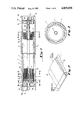
- FIG. 1 is a cut-away view illustrating the spiral wound RFP membrane element of the invention within an external cylindrical pressure housing.
- FIG. 2 is a perspective view of a typical layer arrangement to be wound about a porous tube to produce the spiral wound RFP element of the invention.
- FIG. 3 is an enlarged section of a feed-side view of the RFP element of FIG. 1 taken along line 3--3.
- FIG. 4 is an enlarged cross-section view of a recessed portion of the permeate side of the RFP element of FIG. 1 taken along line 4--4. A portion of this section has been further enlarged in section 4a to show the positional relationship between the constituents.
- FIG. 5 is an enlarged cross-section view of a nonrecessed portion of the permeate side of the RFP element of FIG. 1 taken along line 5--5. A portion of this section has been further enlarged in 5a to show the positional relationship between the constituents.
- FIGS. 6 and 7 which diagrammatically illustrate the prior art elements and the RFP membrane elements of the present invention, respectively, together with their sections 6a and 7a, are included for the purpose of explaining the different membrane flow paths.
- spacer or "spacer sheets” without qualification is intended to define the common porous sheet materials known to the membrane filtration art, particularly the reverse osmosis field, as useful for providing a solid but porous conduit for permeate fluid or turbulence in a stream flowing within a confined channel or merely to space membrane sheets or prevent collapse of the channel between membranes under elevated pressures.
- spacer sheets are normally of fabric or plastic composition but any durable flat sheet material capable of performing the above-stated functions upon assembly into spiral wound membrane elements should be deemed within the purview of the term "spacer.”
- the RFP element which can provide a very long flow path for the feed, it is desirable that fewer, even a single or double membrane envelope will prove most useful for the application intended.
- the RFP element can be designed to achieve the desired conversion within a single element with overall capacity increased by parallel flow through additional elements.
- FIG. 1 shows a cut-away view of a typical reverse osmosis spiral wound membrane element 1 of this invention within a cylindrical RO pressure vessel 2.
- the membrane element 1 is sealed within the pressure vessel 2 with end plates 2a and 2b containing ports for the various feed, concentrate and permeate nozzles and retained in position by ring clamps 10a and 10b.
- "O" ring seals 6, 6a, 6b, 6c, 6d, 6e and 6f are shown as solid dark rectangles at the principle points where the membrane element or its various nozzles are connected to ports of the membrane element 1, the pressure vessel 2, its end plates 2a and 2b.
- At the center of the RFP membrane element 1 is a porous core tube 3 around which the membrane sheets 15 and spacers are spirally wound.
- FIG. 1 shows a cut-away view of a typical reverse osmosis spiral wound membrane element 1 of this invention within a cylindrical RO pressure vessel 2.
- the membrane element 1 is sealed within the pressure vessel 2 with end plates 2a and 2b containing
- the porous core tube 3 contains a tube plug 4 (an adhesive plug) at the product end of membrane element 1 to prevent mixing of feed and permeate at the product end in the porous plate 5 which serves as a conduit for the product leaving the pressure vessel 2 through a permeate nozzle 11.
- Both lateral edges of the membrane element 1 are potted in a low viscosity adhesive 7a and 7b which seals the membrane and spacer ends and bonds the membranes and spacers to the optional end cups 9a and 9b.
- end cups 9a and 9b the membrane element 1 can be optionally sealed in a glue "cup" of the same dimensions.
- the product-side end cup 9b shown in FIG. 1 is cylindrical in shape and contains an "O" ring seal 6b to prevent leakage of concentrate into the porous plate 5.
- the product end cup 9b length be about 6 inches, and about 3 inches in the case of the feed-side end cup 9a.
- the two ends of the membrane element 1 are potted in the end cups 9a and 9b individually, usually starting with the product end followed by the feed end, often on the following day.
- the element may be placed in a pressure chamber and blanketed with nitrogen, at e.g., 50 psig, to insure a bubble and void free seal.
- the element At the product end of the membrane element 1 (see FIG. 1) the element abuts a rigid porous plate 5 which serves to transport the permeate fluid (product) from the product carrier fabric 14 through an outlet nozzle 11.
- the spacers used in the feed-concentrate channel are not shown in FIG. 1.
- the concentrated feed stream flows out of the membrane element 1 from an unsealed end (not illustrated in FIG. 1) of the spiralling radial membrane flow path into an open circumferential chamber 8, defined by the space between the cylindrical element 1 and the cylindrical pressure vessel 2. Openings contained in feed end cup 9a allow the concentrate to pass out of the circumferential chamber 8 into an open space about a feed nozzle 12 and thence exit from the pressure vessel 2 through a concentrate nozzle 13.
- a permeate exit may be contained on both ends with only minor changes in design.
- the sealing technique used for the permeate side in FIG. 1 may be repeated on the opposite side together with a second permeate nozzle 11. Relocation of the concentrate nozzle 13 to another location along the pressure vessel 2 would be simple matter of design convenience.
- FIG. 2 is a diagrammatic illustration of a typical layer arrangement of an RFP spiral wound membrane of the invention containing product carrier fabric 14, a feed spacer, and two membrane sheets 15.
- the product carrier fabric 14 is typically a knit fabric capable of transporting the product fluid (usually water) along the defined permeate flow path.
- the membrane sheets 15 and the feed spacer material are recessed in width with respect to the width of the product carrier fabric 14.
- the preferred recess is about four inches, but at least about one inch, and on the feed side the preferred recess is about one inch, but at least about one-half inch.
- the feed side end cup 9 is of a molded hexagonal configuration with a central opening to accommodate the core tube 3.
- FIGS. 4 and 4a are enlarged cross sections of the element 1 of FIG. 1 and a further enlarged view of the potted permeate fabric of the element, respectively.
- the outer ring is the pressure vessel 2 into which is fitted the product-side end cap 9b.
- the adhesive 7b hydraulically seals the end cup 9b to the spiralling potted carrier fabric 14 (represented by the solid spiralling line) the only sheet of the membrane layer arrangement illustrated in FIG. 2 which extends to the product end of the element 1.
- the permeate carrier fabric with a thin impervious film on either side thereof is shown potted in adhesive 7b.
- the product carrier fabric 14 spirals outwardly from the porous core tube 3, with a central adhesive tube plug 4, to the adhesive layer connecting it to the end cup 9b.
- FIGS. 5 and 5a are views of the non-recessed portion of the membrane element 1 of FIG. 1 along line 5--5.
- the solid spiralling lines represent the membrane sheets 15 and the spaces between represent the feed-concentrate and permeate flow channels with spacers and adhesive 7a omitted.
- the hatched lines represent spacers between membrane leaves. (again the adhesive 7a is omitted).
- FIG. 6 is a diagrammatic representation of a conventional spiral element of the prior art in an exaggerated "unwound" state intended to illustrate the flow direction of the feed-concentrate and permeate in such elements.
- FIG. 6a is a view of the spiral element of FIG. 6 along the line 6a-6a.
- Channels a and c are feed-concentrate channels with b the permeate channel.
- the barrier layer (“skin") sides of the membrane pairs face each other in channels a and c, with spacers not shown, and channel b for permeate is defined by the opposite (permeate) sides of the membrane pairs.
- the feed stream flows axially into one end of the open membrane channels a and c wherein a portion of the feed permeates the membrane skin into the adjacent permeate channel b and the remaining feed (now concentrate) exits through the opposite axial end of the membrane channels.
- the permeate flows inward to the core tube at right angles to the feed, and spirals down to ultimately leave the spiral winding through the porous core tube and out of the element.
- the membrane and spacer leaves are sealed at the indicated places represented by shaded areas in FIG. 6 and 6a.
- the permeate channel b is sealed on all sides except at the openings in the porous core tube. Seals at the core tube between permeate and feed-concentrate channels illustrated in FIG. 6a are essential to prevent mixing at that location.
- FIG. 7 represents a preferred embodiment of the novel RFP element of the invention.
- the feed enters a porous core tube where it is distributed at right angles (see arrows) into the outwardly spiralling membrane channel b.
- FIG. 7a is a view of the spiral element of FIG. 7 along the line 7a--7a. These figures do not accurately show the geometry of the RFP element but are intentionally distorted from scale to more clearly illustrate the flow patterns of the various fluid fractions within the membrane channels.
- the concentrate leaves the membrane channel b at the outer edge of the spiral winding after passing the full length of the membrane channel. As illustrated, the feed-concentrate channel b is sealed at both lateral edges (see FIGS.
- FIG. 7a whereas the permeate channel on the permeate sides of the membranes (illustrated as channels a and b) are sealed at one lateral edge, (see FIG. 7a) longitudinally at the porous core tube, and at the terminal edge of the spiralling membrane sheets (see FIGS. 7 and 7a). Illustrated in FIG. 7a are seals for each membrane at the core tube to prevent lateral mixing of permeate and feed-concentrate.
- the flow path can be shortened or lengthened to "tailor" the flow path to the desired degree of conversion or concentration of the feed.
- the area of the flow path and to a certain extent the type of fluid flow, i.e., whether laminar or turbulent, determines the transmembrane passage of the permeate. Prohibitive back pressure is avoided by allowing the permeate to leave the spiral at right angles to the feed-concentrate flow at one or both axial ends of the cylindrical element.
- Permeation of a portion of the feed through the membrane along the feed-concentrate flow path causes a gradual reduction of the feed volume, thereby diminishing feed velocity in a fixed-dimension channel and reducing the downstream permeation efficiency. This phenomenon is exacerbated by the present invention which provides the possibility of a much longer feed flow path (RFP).
- Design modifications of the RFP element can reduce or virtually eliminate such feed velocity changes. Some of the more obvious design changes include (1) using a tapered spacer to progressively reduce the distance between membranes thereby constricting the downstream flow path and increasing fluid velocity or (2) taper the width of the flow path by sealing the edges closer to the middle along the spiral path.
- a preferred embodiment of the invention utilizes a novel option inherently provided by the RFP to internally "stage" a single element.
- two, three or more membrane envelopes of different lengths can be wound about a single core tube yielding multiple stages as the feed volume decreases along its spiral path (see, e.g., Examples III and IV, infra).
- Various other options should be obvious to those skilled in the art.
- the radially spiralling feed flow path of the invention offers a much longer potential net flow path length than the traditional axial flow direction for the industry's standard spiral modules. This affords correspondingly greater flow conversions without reduction in permeate volume or quality.
- this novel flow path design requires a high pressure seal between the feed and permeate streams located outside of the membrane envelope; a requirement which is not necessary in the standard spiral module flow geometry.
- Such a pressure seal is producable using an adhesive and a compatible bonding surface. Not only must the bonding surface be compatible with the sealing adhesive, it must also act as a shield for the product water carrier to insure an unobstructed pathway for the exiting permeate.
- a hydraulically impervious film onto the product (permeate) carrier fabric at the product end thereof to achieve suitable bonding to seal the product end of the element.
- This coating or film preferably a polymer film or metal foil must be carefully applied to avoid substantial penetration into the knit permeate fabric which could reduce transport of product through the fabric particularly in a reverse osmosis operation. We have found that this may be accomplished by applying a uniform non-porous polyurethane coating to the surface of the fabric which is to be located at the product end.
- the polymer coating is of such composition and thickness that it will adhere uniformly to the surface of the fabric even when the fabric is rolled into a tight cylinder in a spiral membrane element.
- the length of the coating or film should be sufficient to form parallel planar fluid seals about the knitted fabric, usually about 3-12 inches and preferably 6-10 inches long.
- the term "product" is used herein to identify the permeate of a reverse osmosis desalination element.
- the feed-concentrate stream is the true product and the permeate is a waste or recycled stream.
- both the permeate and feed-concentrate streams are considered as product streams in the sense that both have uses after separation, e.g., ultrafiltration of electrocoat paint where both paint solids (concentrate) and permeate water are reused in the painting-rinsing operation.
- the principle of this invention is useful in any spiral wound membrane device employing flat sheet membrane for reverse osmosis, ultrafiltration, membrane softening, microfiltration, and gas separation, requiring the use of recoveries greater than 20/30%, the limit of currently available RO spiral wound elements based on present engineering practice.
- This invention allows a single element ranging in lengths of about 12-60 inches to operate under turbulent or chopped laminar flow conditions at recoveries up to 90% while maintaining boundary layer conditions similar to current brine staged spiral system designs using 12 to 18 elements in series. Said another way, the degree of conversion/recovery of the feed stream is independent of the length of a module, but rather depends upon the length of the radial flow path which affects only the diameter of the module.
- Membranes for UF, RO MF and gas filtration are wellknown in the prior art. Both anisotropic (asymmetric) membranes having a single or double barrier layer (skin) and isotropic membranes are presently made in flat sheet form for UF, RO, MF and gas filtration (see e.g., U.S. Pat. Nos. 3,615,024; 3,597,393; and 3,567,632).
- the membranes may be of a single polymer or of a copolymer, laminated or of a composite structure wherein a thin barrier coating or film, charged or uncharged is formed over a thicker substrate film, the latter being either porous or non-porous (diffusional).
- the polymers suitable for such membranes range from the highly stable hydrophobic materials such as polyvinylidene fluoride, polysulfones, modacrylic copolymers polychloroethers and the like normalloy used for UF, MF and gas filtration applications and as substrates for RO composites, to the hydrophilic polymers such as cellulose acetate and various polyamines (see, e.g., U.S. Pat. Nos. 4,399,035; 4,277,344; 3,951,815; 4,039,440; and 3,615,024).
- spiral wound element may be optionally mounted permanently in its own pressure container or cartridge having suitable fittings for connection to the filtration systems.
- a six inch diameter element was prepared by rolling a single feed channel (2 membranes) element comprising a 280 inch by 40 inch sheet of knitted fabric covered with a plastic coating 3 mils thick at a height of 8 inches on the permeate side.
- the edge of the coatingfabric laminate was sealed with a low viscosity adhesive to prevent the potting adhesive from sealing the permeate water conduit.
- the length of the coating was trimmed so that it covered the fabric for a length of 230 inches. This was necessary to allow sealing the ends of the element with adhesive during the rolling operation.
- a 40 inch porous core tube was mounted on a rolling machine, aligned and then attached to the coated fabric with double sided tape.
- a 280 inch by 33 inch polypropylene brine spacer sheet material was placed between the two sheets of membrane so that the edges were aligned with the two membrane sheets.
- a membrane adhesive was uniformly spread around the entire periphery of the two membrane sheets to form a sealed envelope. The four sheets were then rolled around the core tube to form a spiral element.
- the permeate/coated fabric end of the element was potted in a plastic end cup with a low viscosity adhesive for a length of six inches.
- the potted end was allowed to cure under an 80 psi nitrogen blanket to insure a bubble and void free potting.
- the feed/uncoated side of the element was potted so that the feed core tube was left exposed 1 to 1.5 inches and free from adhesive.
- the feed side was also potted under a nitrogen blanket.
- One inch of the permeate side of the element was trimmed with a saw to open the permeate channel (i.e., expose the knit fabric).
- the element was placed in a pressure vessel with the permeate side supported by a porous support plate and thereafter tested under the following conditions: 270 psi feed pressure, 48% recovery, 3100 ppm NaCl feed solution at 25° C.
- the element produced 494 gallons per day (GPD) at 99.0% rejection with a differential pressure drop of 5 psi between the feed inlet and the permeate.
- a 2.5 inch diameter element was prepared using a 17 inch core tube with a 15 inch wide by 20 inch long piece of coated permeate fabric.
- the coating material was 6 inches high and 8 inches long on the top and bottom of the fabric on the permeate edge.
- Two sheets of a cellulosic membrane with a non-woven substate 12 inches wide by 8 inches long were placed on either side of the fabric material to give a two inch recess from the permeate edge and a one-half inch recess on the feed edge.
- An industrial membrane adhesive was used to bond the membrane to the fabric material on all four sides.
- a piece of brine spacer netting 12 inches wide by 20 inches long was placed on top of the membrane to give the same recess dimensions as the membrane sheets.
- the four sheets of material were then rolled onto the core tube to form a spiral element.
- the next day the feed side was potted using a low viscosity adhesive in such a way as to allow the core tube to be exposed 0.5 to 1 inch and free of adhesive.
- the permeate potting was then trimmed 1 inch to open the coated permeate channel fabric.
- the element was tested at 430 psi, 3000 total dissolved solids (TDS) NaCl feed, 1% recovery, and 25° C. giving a flux of 13.7 GFD at 92.6% rejection.
- a 8.5 inch diameter by 37 inch long element prepared by a procedure similar to Example I has two leaves, one 12 meters in length and one 6 meters in length. The two leaves are rolled into a spiral element and then potted. This results in a configuration with feed brine path lengths and boundary layers similar to conventional brine staged 2-1 arrays of six element pressure vessels. This element can operate at 75% recovery producing 7300 GPD at 97.5% rejection, 270 psi feed, 25° C., 2000 TDS NaCl feed.
- a 12 inch diameter by 60 inch long element containing an 18, 12 and 6 meter leaf is constructed by a procedure similar to Example I. The three leaves are rolled into a spiral element and then potted. This results in a configuration with feed brine path lengths similar to conventional brine staged 3-2-1 arrays of six element pressure vessels. This element can operate at 90% recovery producing 23,000 GPD at 98.0% rejection operating at 420 psi feed pressure, 25° C. and 2000 ppm NaCl feed.
- Example II Following the procedure set forth in Example II an RFP membrane element comprising two membrane leaves of different lengths was assembled.
- the membrane sheet consisted of a polyamide interfacial composite on a polysulfone substrate.
- the element was tested under the following conditions: 270 psi feed pressure, 2100 ppm NaCl feed solution at 25° C., 4% recovery.
- the element produced a flux of 9 GFD at 96.4% rejection of the NaCl.
Abstract
Description
Claims (24)
Priority Applications (1)
| Application Number | Priority Date | Filing Date | Title |
|---|---|---|---|
| US07/188,758 US4855058A (en) | 1986-06-24 | 1988-05-02 | High recovery spiral wound membrane element |
Applications Claiming Priority (2)
| Application Number | Priority Date | Filing Date | Title |
|---|---|---|---|
| US87790686A | 1986-06-24 | 1986-06-24 | |
| US07/188,758 US4855058A (en) | 1986-06-24 | 1988-05-02 | High recovery spiral wound membrane element |
Related Parent Applications (1)
| Application Number | Title | Priority Date | Filing Date |
|---|---|---|---|
| US87790686A Continuation | 1986-06-24 | 1986-06-24 |
Publications (1)
| Publication Number | Publication Date |
|---|---|
| US4855058A true US4855058A (en) | 1989-08-08 |
Family
ID=26884440
Family Applications (1)
| Application Number | Title | Priority Date | Filing Date |
|---|---|---|---|
| US07/188,758 Expired - Fee Related US4855058A (en) | 1986-06-24 | 1988-05-02 | High recovery spiral wound membrane element |
Country Status (1)
| Country | Link |
|---|---|
| US (1) | US4855058A (en) |
Cited By (86)
| Publication number | Priority date | Publication date | Assignee | Title |
|---|---|---|---|---|
| US5039413A (en) * | 1988-04-01 | 1991-08-13 | Pall Corporation | Spiral wrapped fluid treatment element |
| US5053130A (en) * | 1987-08-31 | 1991-10-01 | Gambro Dialysatoren Gmbh & Co. Kg | Diffusion and/or filtration apparatus |
| US5069793A (en) * | 1990-09-12 | 1991-12-03 | Membrane Technology & Research, Inc. | Membrane module |
| US5114582A (en) * | 1991-04-12 | 1992-05-19 | W. R. Grace & Co.-Conn. | Filter element and spiral-wound membrane cartridge containing same |
| US5186832A (en) * | 1991-12-31 | 1993-02-16 | Hoechst Celanese Corporation | Spiral-wound hollow fiber membrane fabric cartridges and modules having integral turbulence promoters |
| US5192437A (en) * | 1990-08-20 | 1993-03-09 | Koch Membrane Systems, Inc. | Spiral filtration module with improved cleanability and operating efficiency |
| US5264171A (en) * | 1991-12-31 | 1993-11-23 | Hoechst Celanese Corporation | Method of making spiral-wound hollow fiber membrane fabric cartridges and modules having flow-directing baffles |
| US5266195A (en) * | 1992-08-10 | 1993-11-30 | Desalination Systems, Inc. | Spiral wound separation device and method of making same |
| US5284584A (en) * | 1992-12-31 | 1994-02-08 | Hoechst Celanese Corporation | Hollow fiber membrane fabric - containing cartridges and modules having solvent-resistant thermoplastic tube sheets, and methods for making the same |
| AU649903B2 (en) * | 1991-12-31 | 1994-06-02 | Hoechst Celanese Corporation | Spiral-wound hollow fiber membrane fabric cartridges and modules having integral turbulence promoters |
| US5403482A (en) * | 1993-10-12 | 1995-04-04 | Gelman Sciences Inc. | Self-supporting, pleated, spirally wound filter and the corresponding process of making |
| US5543047A (en) * | 1992-11-06 | 1996-08-06 | Pall Corporation | Filter with over-laid pleats in intimate contact |
| US5647950A (en) * | 1991-06-28 | 1997-07-15 | Pall Corporation | Filter assembly with a spin welded end cap |
| WO1997029995A1 (en) * | 1996-02-12 | 1997-08-21 | Aqua System A/S | Plant for production of drinking water from unfiltered water |
| US5776342A (en) * | 1995-01-13 | 1998-07-07 | Pall Corporation | Filter assembly |
| WO1999011361A1 (en) * | 1997-08-29 | 1999-03-11 | Hydranautics | Reverse osmosis filter assembly and method of manufacture |
| US6068771A (en) * | 1999-02-11 | 2000-05-30 | Koch Membrane Systems, Inc. | Method for sealing spiral wound filtration modules |
| US6103120A (en) * | 1995-10-23 | 2000-08-15 | Pall Corporation | Fluid processing apparatus |
| US6110368A (en) * | 1994-10-21 | 2000-08-29 | Pall Corporation | Fluid processing apparatus |
| US6168648B1 (en) * | 1997-12-25 | 2001-01-02 | Nitto Denko Corporation | Spiral wound type membrane module, spiral wound type membrane element and running method thereof |
| US20020134716A1 (en) * | 2001-03-06 | 2002-09-26 | Andre Maartens | Monitoring unit for monitoring the condition of a semi-permeable membrane |
| US6632357B1 (en) * | 1999-11-18 | 2003-10-14 | University Of South Florida | Reverse osmosis (“RO”) membrane system incorporating function of flow channel spacer |
| US6702941B1 (en) | 1998-09-09 | 2004-03-09 | Pall Corporation | Fluid treatment elements adapted for cross flow treatment |
| US20040045892A1 (en) * | 2000-12-22 | 2004-03-11 | De La Cruz Deborah | Cross flow filtration materials and cartridges |
| US20040129637A1 (en) * | 2000-07-07 | 2004-07-08 | Hidayat Husain | Multi-stage filtration and softening module and reduced scaling operation |
| US20040222158A1 (en) * | 2003-03-14 | 2004-11-11 | Hidayat Husain | Nanofiltration system for water softening with internally staged spiral wound modules |
| US20050023211A1 (en) * | 1998-08-27 | 2005-02-03 | Koslow Evan E. | Composite filter medium and fluid filters containing same |
| US20050061730A1 (en) * | 2002-01-04 | 2005-03-24 | Enviro Holding A/S | Spiral wound membrane element and a process for preventing telescoping of the filter element |
| US20050194317A1 (en) * | 2004-03-05 | 2005-09-08 | Norio Ikeyama | Filtration devices with embedded radio frequency identification (RFID) tags |
| US20070095756A1 (en) * | 2005-10-31 | 2007-05-03 | General Electric Company | System and method for removal of contaminants from feed solution |
| US20070151925A1 (en) * | 2005-12-29 | 2007-07-05 | Spf Innovations, Llc | Method and apparatus for the filtration of biological solutions |
| US20070292673A1 (en) * | 2004-11-24 | 2007-12-20 | Yuji Katagiri | Inorganic Fiber Paper |
| US7311831B2 (en) | 2000-09-05 | 2007-12-25 | Miox Corporation | Filtration membrane and method of making same |
| US7316780B1 (en) | 1999-01-29 | 2008-01-08 | Pall Corporation | Range separation devices and processes |
| US20080296208A1 (en) * | 2005-09-07 | 2008-12-04 | Norio Ikeyama | Reverse Osmosis Filtration Devices with Rfid Tag-Powered Flow and Conductivity Meters |
| US20080308497A1 (en) * | 2005-12-01 | 2008-12-18 | Malcolm David Walker | Filter Element |
| US20090139650A1 (en) * | 2005-10-31 | 2009-06-04 | General Electric Company | Reverse osmosis membrane and membrane stack assembly |
| JP2009529866A (en) * | 2006-03-16 | 2009-08-27 | デザイン テクノロジー アンド イノベーション リミテッド | Irrigation equipment |
| US7584061B2 (en) | 2006-03-13 | 2009-09-01 | Hydranautics | Device for measuring permeate flow and permeate conductivity of individual reverse osmosis membrane elements |
| US20090255877A1 (en) * | 2008-04-11 | 2009-10-15 | Pall Corporation | Fluid treatment arrangements and methods |
| US20100018924A1 (en) * | 2008-07-28 | 2010-01-28 | Pall Corporation | Fluid treatment arrangements and methods |
| EP2259864A2 (en) * | 2008-03-20 | 2010-12-15 | Yale University | Spiral wound membrane module for forward osmotic use |
| CN101934198A (en) * | 2010-10-07 | 2011-01-05 | 艾欧史密斯(上海)水处理产品有限公司 | Coiling type reverse osmosis membrane element with even water distribution |
| US20110114561A1 (en) * | 2007-12-17 | 2011-05-19 | Nitto Denko Corporation | Spiral type membrane filtering device and mounting member, and membrane filtering device managing system and membrane filtering device managing method using the same |
| US20110120931A1 (en) * | 2008-08-04 | 2011-05-26 | Ulrich Meyer-Blumenroth | Filter Module and System Having Spirally Wound Membrane Filters, and Method for the Production Thereof |
| US20110121574A1 (en) * | 2007-12-17 | 2011-05-26 | Takahisa Konishi | Spiral type membrane element, and spiral type membrane filtering device having the same |
| US20110233128A1 (en) * | 2008-10-17 | 2011-09-29 | General Electric Company | Separator assembly |
| US20110240546A1 (en) * | 2008-10-17 | 2011-10-06 | General Electric Company | Central core element for a separator assembly |
| CN102711964A (en) * | 2010-01-12 | 2012-10-03 | 陶氏环球技术有限责任公司 | Method of testing spiral wound modules by thermal imaging |
| US8337698B2 (en) | 2009-10-30 | 2012-12-25 | A. O. Smith (Shanghai) Water Treatment Products Co., Ltd. | Spiral wound reverse osmosis membrane element |
| CN103007762A (en) * | 2012-12-21 | 2013-04-03 | 杭州自力太阳能科技有限公司 | Ladder water inflowing rolling membrane element of opening water producing runner |
| US20130101797A1 (en) * | 2011-10-19 | 2013-04-25 | General Electric Company | Spiral wound membrane permeate carrier with thin border |
| US8883007B2 (en) | 2009-02-25 | 2014-11-11 | Aerojet Rocketdyne Of De, Inc. | Fluid separation system with reduced fouling |
| US20150144547A1 (en) * | 2013-11-26 | 2015-05-28 | General Electric Company | Spiral flow water treatment apparatus |
| US9095823B2 (en) | 2012-03-29 | 2015-08-04 | Lockheed Martin Corporation | Tunable layered membrane configuration for filtration and selective isolation and recovery devices |
| US20150285563A1 (en) * | 2014-04-08 | 2015-10-08 | Toyota Jidosha Kabushiki Kaisha | Heat pipe |
| US9463421B2 (en) | 2012-03-29 | 2016-10-11 | Lockheed Martin Corporation | Planar filtration and selective isolation and recovery device |
| US9522363B2 (en) | 2011-10-19 | 2016-12-20 | General Electric Company | Material efficiency and fabrication of membrane elements |
| WO2017049600A1 (en) * | 2015-09-25 | 2017-03-30 | General Electric Company | Multi-media filter with spiral flow element |
| US9636637B2 (en) | 2012-06-13 | 2017-05-02 | Glen Raven, Inc. | Permeate carrier fabric for membrane filters |
| US9744617B2 (en) | 2014-01-31 | 2017-08-29 | Lockheed Martin Corporation | Methods for perforating multi-layer graphene through ion bombardment |
| WO2017174192A1 (en) * | 2016-04-05 | 2017-10-12 | Sartorius Stedim Biotech Gmbh | Cross-flow filtration unit for continuous diafiltration |
| US9833748B2 (en) | 2010-08-25 | 2017-12-05 | Lockheed Martin Corporation | Perforated graphene deionization or desalination |
| US9834809B2 (en) | 2014-02-28 | 2017-12-05 | Lockheed Martin Corporation | Syringe for obtaining nano-sized materials for selective assays and related methods of use |
| US9844757B2 (en) | 2014-03-12 | 2017-12-19 | Lockheed Martin Corporation | Separation membranes formed from perforated graphene and methods for use thereof |
| US9870895B2 (en) | 2014-01-31 | 2018-01-16 | Lockheed Martin Corporation | Methods for perforating two-dimensional materials using a broad ion field |
| US10005038B2 (en) | 2014-09-02 | 2018-06-26 | Lockheed Martin Corporation | Hemodialysis and hemofiltration membranes based upon a two-dimensional membrane material and methods employing same |
| US10017852B2 (en) | 2016-04-14 | 2018-07-10 | Lockheed Martin Corporation | Method for treating graphene sheets for large-scale transfer using free-float method |
| WO2018194911A1 (en) | 2017-04-20 | 2018-10-25 | Aqua Membranes Llc | Non-nesting, non-deforming patterns for spiral-wound elements |
| US10118130B2 (en) | 2016-04-14 | 2018-11-06 | Lockheed Martin Corporation | Two-dimensional membrane structures having flow passages |
| US10203295B2 (en) | 2016-04-14 | 2019-02-12 | Lockheed Martin Corporation | Methods for in situ monitoring and control of defect formation or healing |
| US10201784B2 (en) | 2013-03-12 | 2019-02-12 | Lockheed Martin Corporation | Method for forming perforated graphene with uniform aperture size |
| US10213746B2 (en) | 2016-04-14 | 2019-02-26 | Lockheed Martin Corporation | Selective interfacial mitigation of graphene defects |
| US10376845B2 (en) | 2016-04-14 | 2019-08-13 | Lockheed Martin Corporation | Membranes with tunable selectivity |
| US10418143B2 (en) | 2015-08-05 | 2019-09-17 | Lockheed Martin Corporation | Perforatable sheets of graphene-based material |
| US10471391B2 (en) | 2016-11-19 | 2019-11-12 | Aqua Membranes, Inc. | Flow directing devices for spiral-wound elements |
| US10471199B2 (en) | 2013-06-21 | 2019-11-12 | Lockheed Martin Corporation | Graphene-based filter for isolating a substance from blood |
| CN110461445A (en) * | 2017-04-12 | 2019-11-15 | 阿夸曼布拉尼斯公司 | Classification distance part for takeup type filter element |
| US10500546B2 (en) | 2014-01-31 | 2019-12-10 | Lockheed Martin Corporation | Processes for forming composite structures with a two-dimensional material using a porous, non-sacrificial supporting layer |
| US10653824B2 (en) | 2012-05-25 | 2020-05-19 | Lockheed Martin Corporation | Two-dimensional materials and uses thereof |
| US10696554B2 (en) | 2015-08-06 | 2020-06-30 | Lockheed Martin Corporation | Nanoparticle modification and perforation of graphene |
| US10980919B2 (en) | 2016-04-14 | 2021-04-20 | Lockheed Martin Corporation | Methods for in vivo and in vitro use of graphene and other two-dimensional materials |
| US11376552B2 (en) | 2016-09-20 | 2022-07-05 | Aqua Membranes Inc. | Permeate flow paterns |
| US11633700B2 (en) | 2020-04-07 | 2023-04-25 | Aqua Membranes Inc. | Independent spacers and methods |
| US11745143B2 (en) | 2017-04-20 | 2023-09-05 | Aqua Membranes, Inc. | Mixing-promoting spacer patterns for spiral-wound elements |
| US11745144B2 (en) | 2017-10-13 | 2023-09-05 | Aqua Membranes Inc. | Bridge support and reduced feed spacers for spiral-wound elements |
Citations (17)
| Publication number | Priority date | Publication date | Assignee | Title |
|---|---|---|---|---|
| US3252272A (en) * | 1962-01-11 | 1966-05-24 | Kerr Mc Gee Oil Ind Inc | Apparatus for separating materials |
| US3367504A (en) * | 1964-12-21 | 1968-02-06 | Gulf General Atomic Inc | Spirally wrapped reverse osmosis membrane cell |
| US3417870A (en) * | 1965-03-22 | 1968-12-24 | Gulf General Atomic Inc | Reverse osmosis purification apparatus |
| US3493496A (en) * | 1968-05-13 | 1970-02-03 | Desalination Systems | Purified water supply apparatus and method |
| US3504796A (en) * | 1968-08-01 | 1970-04-07 | Desalination Systems | Reverse osmosis apparatus |
| US3567632A (en) * | 1968-09-04 | 1971-03-02 | Du Pont | Permselective,aromatic,nitrogen-containing polymeric membranes |
| US3597393A (en) * | 1969-01-21 | 1971-08-03 | Monsanto Co | Functionally substituted highly ordered azo-aromatic polyamides |
| US3615024A (en) * | 1968-08-26 | 1971-10-26 | Amicon Corp | High flow membrane |
| US3933646A (en) * | 1973-05-14 | 1976-01-20 | Toray Industries, Inc. | Reverse osmosis separation apparatus |
| US3951815A (en) * | 1974-09-05 | 1976-04-20 | Universal Oil Products Company | Composite semipermeable membranes made from polyethylenimine |
| US4039440A (en) * | 1972-09-19 | 1977-08-02 | The United States Of America As Represented By The Secretary Of The Interior | Reverse osmosis membrane |
| JPS53124179A (en) * | 1977-04-06 | 1978-10-30 | Toray Ind Inc | Separating element of spiral shape for liquid |
| US4235723A (en) * | 1979-05-15 | 1980-11-25 | Hydranautics | Reverse osmosis membrane module |
| US4277344A (en) * | 1979-02-22 | 1981-07-07 | Filmtec Corporation | Interfacially synthesized reverse osmosis membrane |
| US4392958A (en) * | 1980-02-14 | 1983-07-12 | Millipore Corporation | Method and structure for sealing tubular filter elements |
| US4399035A (en) * | 1979-10-15 | 1983-08-16 | Asahi Kasei Kogyo Kabushiki Kaisha | Polyvinylidene fluoride type resin hollow filament microfilter and process for producing the same |
| DE3220613A1 (en) * | 1982-06-01 | 1983-12-01 | GFT Ingenieurbüro für Industrieanlagenbau, 6650 Homburg | MEMBRANE MODULE AND ITS USE FOR SEPARATING LIQUIDS BY PERVAPORATION PROCESS |
-
1988
- 1988-05-02 US US07/188,758 patent/US4855058A/en not_active Expired - Fee Related
Patent Citations (17)
| Publication number | Priority date | Publication date | Assignee | Title |
|---|---|---|---|---|
| US3252272A (en) * | 1962-01-11 | 1966-05-24 | Kerr Mc Gee Oil Ind Inc | Apparatus for separating materials |
| US3367504A (en) * | 1964-12-21 | 1968-02-06 | Gulf General Atomic Inc | Spirally wrapped reverse osmosis membrane cell |
| US3417870A (en) * | 1965-03-22 | 1968-12-24 | Gulf General Atomic Inc | Reverse osmosis purification apparatus |
| US3493496A (en) * | 1968-05-13 | 1970-02-03 | Desalination Systems | Purified water supply apparatus and method |
| US3504796A (en) * | 1968-08-01 | 1970-04-07 | Desalination Systems | Reverse osmosis apparatus |
| US3615024A (en) * | 1968-08-26 | 1971-10-26 | Amicon Corp | High flow membrane |
| US3567632A (en) * | 1968-09-04 | 1971-03-02 | Du Pont | Permselective,aromatic,nitrogen-containing polymeric membranes |
| US3597393A (en) * | 1969-01-21 | 1971-08-03 | Monsanto Co | Functionally substituted highly ordered azo-aromatic polyamides |
| US4039440A (en) * | 1972-09-19 | 1977-08-02 | The United States Of America As Represented By The Secretary Of The Interior | Reverse osmosis membrane |
| US3933646A (en) * | 1973-05-14 | 1976-01-20 | Toray Industries, Inc. | Reverse osmosis separation apparatus |
| US3951815A (en) * | 1974-09-05 | 1976-04-20 | Universal Oil Products Company | Composite semipermeable membranes made from polyethylenimine |
| JPS53124179A (en) * | 1977-04-06 | 1978-10-30 | Toray Ind Inc | Separating element of spiral shape for liquid |
| US4277344A (en) * | 1979-02-22 | 1981-07-07 | Filmtec Corporation | Interfacially synthesized reverse osmosis membrane |
| US4235723A (en) * | 1979-05-15 | 1980-11-25 | Hydranautics | Reverse osmosis membrane module |
| US4399035A (en) * | 1979-10-15 | 1983-08-16 | Asahi Kasei Kogyo Kabushiki Kaisha | Polyvinylidene fluoride type resin hollow filament microfilter and process for producing the same |
| US4392958A (en) * | 1980-02-14 | 1983-07-12 | Millipore Corporation | Method and structure for sealing tubular filter elements |
| DE3220613A1 (en) * | 1982-06-01 | 1983-12-01 | GFT Ingenieurbüro für Industrieanlagenbau, 6650 Homburg | MEMBRANE MODULE AND ITS USE FOR SEPARATING LIQUIDS BY PERVAPORATION PROCESS |
Cited By (140)
| Publication number | Priority date | Publication date | Assignee | Title |
|---|---|---|---|---|
| US5053130A (en) * | 1987-08-31 | 1991-10-01 | Gambro Dialysatoren Gmbh & Co. Kg | Diffusion and/or filtration apparatus |
| US5039413A (en) * | 1988-04-01 | 1991-08-13 | Pall Corporation | Spiral wrapped fluid treatment element |
| US5192437A (en) * | 1990-08-20 | 1993-03-09 | Koch Membrane Systems, Inc. | Spiral filtration module with improved cleanability and operating efficiency |
| US5069793A (en) * | 1990-09-12 | 1991-12-03 | Membrane Technology & Research, Inc. | Membrane module |
| US5114582A (en) * | 1991-04-12 | 1992-05-19 | W. R. Grace & Co.-Conn. | Filter element and spiral-wound membrane cartridge containing same |
| US5871645A (en) * | 1991-06-28 | 1999-02-16 | Pall Corporation | Filter arrangement including a non-perforated housing and an axially pleated filter pack |
| US5647950A (en) * | 1991-06-28 | 1997-07-15 | Pall Corporation | Filter assembly with a spin welded end cap |
| US5186832A (en) * | 1991-12-31 | 1993-02-16 | Hoechst Celanese Corporation | Spiral-wound hollow fiber membrane fabric cartridges and modules having integral turbulence promoters |
| US5264171A (en) * | 1991-12-31 | 1993-11-23 | Hoechst Celanese Corporation | Method of making spiral-wound hollow fiber membrane fabric cartridges and modules having flow-directing baffles |
| AU649903B2 (en) * | 1991-12-31 | 1994-06-02 | Hoechst Celanese Corporation | Spiral-wound hollow fiber membrane fabric cartridges and modules having integral turbulence promoters |
| US5352361A (en) * | 1991-12-31 | 1994-10-04 | Hoechst Celanese Corporation | Spiral-wound hollow fiber membrane fabric cartridges and modules having flow-directing baffles |
| US5266195A (en) * | 1992-08-10 | 1993-11-30 | Desalination Systems, Inc. | Spiral wound separation device and method of making same |
| US6113784A (en) | 1992-11-06 | 2000-09-05 | Pall Corporation | Filter |
| US5543047A (en) * | 1992-11-06 | 1996-08-06 | Pall Corporation | Filter with over-laid pleats in intimate contact |
| US5876601A (en) * | 1992-11-06 | 1999-03-02 | Pall Corporation | Pleated filter having a helically wrapped septum to tension the filter |
| US5725784A (en) * | 1992-11-06 | 1998-03-10 | Pall Corporation | Filtering method |
| US5284584A (en) * | 1992-12-31 | 1994-02-08 | Hoechst Celanese Corporation | Hollow fiber membrane fabric - containing cartridges and modules having solvent-resistant thermoplastic tube sheets, and methods for making the same |
| US5472606A (en) * | 1993-10-12 | 1995-12-05 | Gelman Sciences Inc. | Self-supporting, pleated, spirally wound filter |
| US5403482A (en) * | 1993-10-12 | 1995-04-04 | Gelman Sciences Inc. | Self-supporting, pleated, spirally wound filter and the corresponding process of making |
| US6110368A (en) * | 1994-10-21 | 2000-08-29 | Pall Corporation | Fluid processing apparatus |
| US5776342A (en) * | 1995-01-13 | 1998-07-07 | Pall Corporation | Filter assembly |
| US6103120A (en) * | 1995-10-23 | 2000-08-15 | Pall Corporation | Fluid processing apparatus |
| WO1997029995A1 (en) * | 1996-02-12 | 1997-08-21 | Aqua System A/S | Plant for production of drinking water from unfiltered water |
| WO1999011361A1 (en) * | 1997-08-29 | 1999-03-11 | Hydranautics | Reverse osmosis filter assembly and method of manufacture |
| US6168648B1 (en) * | 1997-12-25 | 2001-01-02 | Nitto Denko Corporation | Spiral wound type membrane module, spiral wound type membrane element and running method thereof |
| US20050023211A1 (en) * | 1998-08-27 | 2005-02-03 | Koslow Evan E. | Composite filter medium and fluid filters containing same |
| US20040089600A1 (en) * | 1998-09-09 | 2004-05-13 | Pall Corporation | Fluid treatment elements |
| US6702941B1 (en) | 1998-09-09 | 2004-03-09 | Pall Corporation | Fluid treatment elements adapted for cross flow treatment |
| US6932907B2 (en) | 1998-09-09 | 2005-08-23 | Pall Corporation | Fluid treatment elements |
| US7316780B1 (en) | 1999-01-29 | 2008-01-08 | Pall Corporation | Range separation devices and processes |
| US6068771A (en) * | 1999-02-11 | 2000-05-30 | Koch Membrane Systems, Inc. | Method for sealing spiral wound filtration modules |
| US6632357B1 (en) * | 1999-11-18 | 2003-10-14 | University Of South Florida | Reverse osmosis (“RO”) membrane system incorporating function of flow channel spacer |
| US20040129637A1 (en) * | 2000-07-07 | 2004-07-08 | Hidayat Husain | Multi-stage filtration and softening module and reduced scaling operation |
| US7311831B2 (en) | 2000-09-05 | 2007-12-25 | Miox Corporation | Filtration membrane and method of making same |
| US20040045892A1 (en) * | 2000-12-22 | 2004-03-11 | De La Cruz Deborah | Cross flow filtration materials and cartridges |
| US7048855B2 (en) | 2000-12-22 | 2006-05-23 | Ge Osmonics, Inc. | Cross flow filtration materials and cartridges |
| US7186331B2 (en) * | 2001-03-06 | 2007-03-06 | Sasol Technology (Pty) Limited | Monitoring unit for monitoring the condition of a semi-permeable membrane |
| US20020134716A1 (en) * | 2001-03-06 | 2002-09-26 | Andre Maartens | Monitoring unit for monitoring the condition of a semi-permeable membrane |
| US20050061730A1 (en) * | 2002-01-04 | 2005-03-24 | Enviro Holding A/S | Spiral wound membrane element and a process for preventing telescoping of the filter element |
| US7396463B2 (en) | 2002-01-04 | 2008-07-08 | Enviro Holding A/S | Spiral wound membrane element and a process for preventing telescoping of the filter element |
| US20050284806A1 (en) * | 2003-03-14 | 2005-12-29 | Hidayat Husain | Nanofiltration system for water softening with internally staged spiral wound modules |
| US20040222158A1 (en) * | 2003-03-14 | 2004-11-11 | Hidayat Husain | Nanofiltration system for water softening with internally staged spiral wound modules |
| US20050194317A1 (en) * | 2004-03-05 | 2005-09-08 | Norio Ikeyama | Filtration devices with embedded radio frequency identification (RFID) tags |
| US7481917B2 (en) | 2004-03-05 | 2009-01-27 | Hydranautics | Filtration devices with embedded radio frequency identification (RFID) tags |
| US7736495B2 (en) | 2004-03-05 | 2010-06-15 | Hydranautics | Filtration devices with embedded radio frequency identification (RFID) tags |
| US20090032477A1 (en) * | 2004-03-05 | 2009-02-05 | Hydranautics | Filtration devices with embedded radio frequency identification (rfid) tags |
| US20070292673A1 (en) * | 2004-11-24 | 2007-12-20 | Yuji Katagiri | Inorganic Fiber Paper |
| US8617397B2 (en) | 2005-09-07 | 2013-12-31 | Hydranautics | Reverse osmosis filtration devices with RFID tag-powered flow and conductivity meters |
| US20080296208A1 (en) * | 2005-09-07 | 2008-12-04 | Norio Ikeyama | Reverse Osmosis Filtration Devices with Rfid Tag-Powered Flow and Conductivity Meters |
| US20070095756A1 (en) * | 2005-10-31 | 2007-05-03 | General Electric Company | System and method for removal of contaminants from feed solution |
| US20090139650A1 (en) * | 2005-10-31 | 2009-06-04 | General Electric Company | Reverse osmosis membrane and membrane stack assembly |
| US20080308497A1 (en) * | 2005-12-01 | 2008-12-18 | Malcolm David Walker | Filter Element |
| US10421043B2 (en) | 2005-12-29 | 2019-09-24 | Spf Innovations, Llc | Method and apparatus for the filtration of biological solutions |
| US8728315B2 (en) | 2005-12-29 | 2014-05-20 | Spf Innovations, Llc | Method and apparatus for the filtration of biological solutions |
| US7967987B2 (en) | 2005-12-29 | 2011-06-28 | Spf Innovations, Llc | Method and apparatus for the filtration of biological solutions |
| US9662614B2 (en) | 2005-12-29 | 2017-05-30 | Spf Innovations Llc | Method and apparatus for the filtration of biological solutions |
| EP3415214A2 (en) | 2005-12-29 | 2018-12-19 | SPF Innovations, LLC. | Method and apparatus for the filtration of biological solutions |
| US20080245733A1 (en) * | 2005-12-29 | 2008-10-09 | Spf Innovations, Llc | Method and apparatus for the filtration of biological solutions |
| US7682511B2 (en) | 2005-12-29 | 2010-03-23 | Spf Innovations, Llc | Method and apparatus for the filtration of biological solutions |
| US20100133185A1 (en) * | 2005-12-29 | 2010-06-03 | Spf Innovations, Llc | Method and apparatus for the filtration of biological solutions |
| US7384549B2 (en) | 2005-12-29 | 2008-06-10 | Spf Innovations, Llc | Method and apparatus for the filtration of biological solutions |
| US8157999B2 (en) | 2005-12-29 | 2012-04-17 | Spf Innovations, Llc | Method and apparatus for the filtration of biological solutions |
| US11633698B2 (en) | 2005-12-29 | 2023-04-25 | Spf Innovations, Llc | Method and apparatus for the filtration of biological solutions |
| US11007483B2 (en) | 2005-12-29 | 2021-05-18 | Spf Innovations, Llc | Method and apparatus for the filtration of biological solutions |
| US20070151925A1 (en) * | 2005-12-29 | 2007-07-05 | Spf Innovations, Llc | Method and apparatus for the filtration of biological solutions |
| US20110215051A1 (en) * | 2005-12-29 | 2011-09-08 | Spf Innovations, Llc | Method and apparatus for the filtration of biological solutions |
| US7584061B2 (en) | 2006-03-13 | 2009-09-01 | Hydranautics | Device for measuring permeate flow and permeate conductivity of individual reverse osmosis membrane elements |
| US20090320563A1 (en) * | 2006-03-13 | 2009-12-31 | Hydranautics | Device for measuring permeate flow and permeate conductivity of individual reverse osmosis membrane elements |
| JP2009529866A (en) * | 2006-03-16 | 2009-08-27 | デザイン テクノロジー アンド イノベーション リミテッド | Irrigation equipment |
| US20110114561A1 (en) * | 2007-12-17 | 2011-05-19 | Nitto Denko Corporation | Spiral type membrane filtering device and mounting member, and membrane filtering device managing system and membrane filtering device managing method using the same |
| US20110121574A1 (en) * | 2007-12-17 | 2011-05-26 | Takahisa Konishi | Spiral type membrane element, and spiral type membrane filtering device having the same |
| US8519559B2 (en) * | 2007-12-17 | 2013-08-27 | Nitto Denko Corporation | Spiral type membrane element, and spiral type membrane filtering device having the same |
| US20110036774A1 (en) * | 2008-03-20 | 2011-02-17 | Yale University | Spiral Wound Membrane Module for Forward Osmotic Use |
| AU2009258055B2 (en) * | 2008-03-20 | 2014-01-23 | Yale University | Spiral wound membrane module for forward osmotic use |
| EP2259864A4 (en) * | 2008-03-20 | 2012-11-07 | Univ Yale | Spiral wound membrane module for forward osmotic use |
| EP2259864A2 (en) * | 2008-03-20 | 2010-12-15 | Yale University | Spiral wound membrane module for forward osmotic use |
| US8815091B2 (en) | 2008-03-20 | 2014-08-26 | Yale University | Spiral wound membrane module for forward osmotic use |
| US8043512B2 (en) | 2008-04-11 | 2011-10-25 | Pall Corporation | Fluid treatment arrangements and methods |
| US20090255877A1 (en) * | 2008-04-11 | 2009-10-15 | Pall Corporation | Fluid treatment arrangements and methods |
| US8048315B2 (en) | 2008-07-28 | 2011-11-01 | Pall Corporation | Fluid treatment arrangements and methods |
| US20100018924A1 (en) * | 2008-07-28 | 2010-01-28 | Pall Corporation | Fluid treatment arrangements and methods |
| US20110120931A1 (en) * | 2008-08-04 | 2011-05-26 | Ulrich Meyer-Blumenroth | Filter Module and System Having Spirally Wound Membrane Filters, and Method for the Production Thereof |
| US9050564B2 (en) * | 2008-08-04 | 2015-06-09 | Mn Beteiligungs Gmbh | Filter module and system having spirally wound membrane filters, and method for the production thereof |
| US20110233128A1 (en) * | 2008-10-17 | 2011-09-29 | General Electric Company | Separator assembly |
| US20110240546A1 (en) * | 2008-10-17 | 2011-10-06 | General Electric Company | Central core element for a separator assembly |
| US8968566B2 (en) * | 2008-10-17 | 2015-03-03 | General Electric Company | Separator assembly |
| US8883007B2 (en) | 2009-02-25 | 2014-11-11 | Aerojet Rocketdyne Of De, Inc. | Fluid separation system with reduced fouling |
| US8337698B2 (en) | 2009-10-30 | 2012-12-25 | A. O. Smith (Shanghai) Water Treatment Products Co., Ltd. | Spiral wound reverse osmosis membrane element |
| CN102711964A (en) * | 2010-01-12 | 2012-10-03 | 陶氏环球技术有限责任公司 | Method of testing spiral wound modules by thermal imaging |
| CN102711964B (en) * | 2010-01-12 | 2014-10-22 | 陶氏环球技术有限责任公司 | Method of testing spiral wound modules by thermal imaging |
| US9833748B2 (en) | 2010-08-25 | 2017-12-05 | Lockheed Martin Corporation | Perforated graphene deionization or desalination |
| CN101934198A (en) * | 2010-10-07 | 2011-01-05 | 艾欧史密斯(上海)水处理产品有限公司 | Coiling type reverse osmosis membrane element with even water distribution |
| US10583400B2 (en) | 2011-10-19 | 2020-03-10 | Bl Technologies, Inc. | Material efficiency and fabrication of membrane elements |
| US9522363B2 (en) | 2011-10-19 | 2016-12-20 | General Electric Company | Material efficiency and fabrication of membrane elements |
| US20130101797A1 (en) * | 2011-10-19 | 2013-04-25 | General Electric Company | Spiral wound membrane permeate carrier with thin border |
| US9675937B2 (en) * | 2011-10-19 | 2017-06-13 | General Electric Company | Spiral wound membrane permeate carrier with thin border |
| US9463421B2 (en) | 2012-03-29 | 2016-10-11 | Lockheed Martin Corporation | Planar filtration and selective isolation and recovery device |
| US9095823B2 (en) | 2012-03-29 | 2015-08-04 | Lockheed Martin Corporation | Tunable layered membrane configuration for filtration and selective isolation and recovery devices |
| US10653824B2 (en) | 2012-05-25 | 2020-05-19 | Lockheed Martin Corporation | Two-dimensional materials and uses thereof |
| US9636637B2 (en) | 2012-06-13 | 2017-05-02 | Glen Raven, Inc. | Permeate carrier fabric for membrane filters |
| CN103007762B (en) * | 2012-12-21 | 2014-12-10 | 杭州自力太阳能科技有限公司 | Ladder water inflowing rolling membrane element of opening water producing runner |
| CN103007762A (en) * | 2012-12-21 | 2013-04-03 | 杭州自力太阳能科技有限公司 | Ladder water inflowing rolling membrane element of opening water producing runner |
| US10201784B2 (en) | 2013-03-12 | 2019-02-12 | Lockheed Martin Corporation | Method for forming perforated graphene with uniform aperture size |
| US10471199B2 (en) | 2013-06-21 | 2019-11-12 | Lockheed Martin Corporation | Graphene-based filter for isolating a substance from blood |
| US20150144547A1 (en) * | 2013-11-26 | 2015-05-28 | General Electric Company | Spiral flow water treatment apparatus |
| US9744617B2 (en) | 2014-01-31 | 2017-08-29 | Lockheed Martin Corporation | Methods for perforating multi-layer graphene through ion bombardment |
| US10500546B2 (en) | 2014-01-31 | 2019-12-10 | Lockheed Martin Corporation | Processes for forming composite structures with a two-dimensional material using a porous, non-sacrificial supporting layer |
| US9870895B2 (en) | 2014-01-31 | 2018-01-16 | Lockheed Martin Corporation | Methods for perforating two-dimensional materials using a broad ion field |
| US9834809B2 (en) | 2014-02-28 | 2017-12-05 | Lockheed Martin Corporation | Syringe for obtaining nano-sized materials for selective assays and related methods of use |
| US9844757B2 (en) | 2014-03-12 | 2017-12-19 | Lockheed Martin Corporation | Separation membranes formed from perforated graphene and methods for use thereof |
| US20150285563A1 (en) * | 2014-04-08 | 2015-10-08 | Toyota Jidosha Kabushiki Kaisha | Heat pipe |
| US9982949B2 (en) * | 2014-04-08 | 2018-05-29 | Toyota Jidosha Kabushiki Kaisha | Heat pipe having wick formed with hydrophilic and water-repellent treated surfaces |
| US10005038B2 (en) | 2014-09-02 | 2018-06-26 | Lockheed Martin Corporation | Hemodialysis and hemofiltration membranes based upon a two-dimensional membrane material and methods employing same |
| US10418143B2 (en) | 2015-08-05 | 2019-09-17 | Lockheed Martin Corporation | Perforatable sheets of graphene-based material |
| US10696554B2 (en) | 2015-08-06 | 2020-06-30 | Lockheed Martin Corporation | Nanoparticle modification and perforation of graphene |
| WO2017049600A1 (en) * | 2015-09-25 | 2017-03-30 | General Electric Company | Multi-media filter with spiral flow element |
| CN108778470A (en) * | 2016-04-05 | 2018-11-09 | 赛多利斯司特蒂姆生物工艺公司 | Cross-filtration unit for continuous diffusion |
| WO2017174192A1 (en) * | 2016-04-05 | 2017-10-12 | Sartorius Stedim Biotech Gmbh | Cross-flow filtration unit for continuous diafiltration |
| US11612861B2 (en) | 2016-04-05 | 2023-03-28 | Sartorius Stedim Biotech Gmbh | Crossflow filtration unit for continuous diafiltration |
| US10203295B2 (en) | 2016-04-14 | 2019-02-12 | Lockheed Martin Corporation | Methods for in situ monitoring and control of defect formation or healing |
| US10017852B2 (en) | 2016-04-14 | 2018-07-10 | Lockheed Martin Corporation | Method for treating graphene sheets for large-scale transfer using free-float method |
| US10118130B2 (en) | 2016-04-14 | 2018-11-06 | Lockheed Martin Corporation | Two-dimensional membrane structures having flow passages |
| US10376845B2 (en) | 2016-04-14 | 2019-08-13 | Lockheed Martin Corporation | Membranes with tunable selectivity |
| US10213746B2 (en) | 2016-04-14 | 2019-02-26 | Lockheed Martin Corporation | Selective interfacial mitigation of graphene defects |
| US10981120B2 (en) | 2016-04-14 | 2021-04-20 | Lockheed Martin Corporation | Selective interfacial mitigation of graphene defects |
| US10980919B2 (en) | 2016-04-14 | 2021-04-20 | Lockheed Martin Corporation | Methods for in vivo and in vitro use of graphene and other two-dimensional materials |
| US11376552B2 (en) | 2016-09-20 | 2022-07-05 | Aqua Membranes Inc. | Permeate flow paterns |
| US10471391B2 (en) | 2016-11-19 | 2019-11-12 | Aqua Membranes, Inc. | Flow directing devices for spiral-wound elements |
| US11040311B2 (en) | 2016-11-19 | 2021-06-22 | Aqua Membranes Inc. | Interference patterns for spiral wound elements |
| CN110461445A (en) * | 2017-04-12 | 2019-11-15 | 阿夸曼布拉尼斯公司 | Classification distance part for takeup type filter element |
| US11090612B2 (en) | 2017-04-12 | 2021-08-17 | Aqua Membranes Inc. | Graded spacers for filtration wound elements |
| CN110461445B (en) * | 2017-04-12 | 2022-10-21 | 阿夸曼布拉尼斯公司 | Stepped spacer for coiled filter elements |
| US11612862B2 (en) | 2017-04-12 | 2023-03-28 | Aqua Membranes Inc. | Graded spacers in spiral wound elements |
| EP3609607A4 (en) * | 2017-04-12 | 2021-01-27 | Aqua Membranes, Inc. | Graded spacers for filtration wound elements |
| US11083997B2 (en) | 2017-04-20 | 2021-08-10 | Aqua Membranes Inc. | Non-nesting, non-deforming patterns for spiral-wound elements |
| WO2018194911A1 (en) | 2017-04-20 | 2018-10-25 | Aqua Membranes Llc | Non-nesting, non-deforming patterns for spiral-wound elements |
| US11745143B2 (en) | 2017-04-20 | 2023-09-05 | Aqua Membranes, Inc. | Mixing-promoting spacer patterns for spiral-wound elements |
| US11896933B2 (en) | 2017-04-20 | 2024-02-13 | Aqua Membranes Inc. | Non-nesting, non-deforming patterns for spiral-wound elements |
| US11745144B2 (en) | 2017-10-13 | 2023-09-05 | Aqua Membranes Inc. | Bridge support and reduced feed spacers for spiral-wound elements |
| US11633700B2 (en) | 2020-04-07 | 2023-04-25 | Aqua Membranes Inc. | Independent spacers and methods |
Similar Documents
| Publication | Publication Date | Title |
|---|---|---|
| US4855058A (en) | High recovery spiral wound membrane element | |
| EP0251620B1 (en) | Spiral wound membrane filtration device and filtration method using such device | |
| US4756835A (en) | Permeable membranes having high flux-density and low fouling-propensity | |
| US5460720A (en) | Pleated membrane crossflow fluid separation device | |
| US4902417A (en) | Spiral-wound membrane cartridge with ribbed and spaced carrier layer | |
| US5266195A (en) | Spiral wound separation device and method of making same | |
| US7048855B2 (en) | Cross flow filtration materials and cartridges | |
| US5458774A (en) | Corrugated spiral membrane module | |
| JPH06165923A (en) | Cartridge of wafer of hollow fiber thin film and module with piled cartridge | |
| US10717050B2 (en) | Spiral wound membrane module adapted for high recovery | |
| JP6475326B2 (en) | A spiral filtration assembly including an integral bioreactor | |
| US5232593A (en) | Cartridge of hollow fiber membrane wafers and module containing stacked cartridges | |
| EP3283197B1 (en) | Filtration assembly including spiral wound bioreactors and membrane modules positioned in separate pressure vessels | |
| US10286361B2 (en) | Filtration assembly including spiral wound bioreactors and hyperfiltration membrane modules | |
| US20150182918A1 (en) | Multi-pass hyperfiltration system | |
| US20220288535A1 (en) | Preferred Flow Paths for Spiral-Wound Elements | |
| CN107684830B (en) | Membrane, membrane element and method for producing the same |
Legal Events
| Date | Code | Title | Description |
|---|---|---|---|
| AS | Assignment |
Owner name: HYDRANAUTICS, CALIFORNIA Free format text: ASSIGNMENT OF ASSIGNORS INTEREST.;ASSIGNORS:HOLLAND, ERIC C.;LESAN, FREDRICK K.;KNAPPE, PETER H.;REEL/FRAME:005093/0921 Effective date: 19860611 |
|
| FEPP | Fee payment procedure |
Free format text: PAYOR NUMBER ASSIGNED (ORIGINAL EVENT CODE: ASPN); ENTITY STATUS OF PATENT OWNER: LARGE ENTITY |
|
| FPAY | Fee payment |
Year of fee payment: 4 |
|
| FEPP | Fee payment procedure |
Free format text: PAYOR NUMBER ASSIGNED (ORIGINAL EVENT CODE: ASPN); ENTITY STATUS OF PATENT OWNER: LARGE ENTITY Free format text: PAYER NUMBER DE-ASSIGNED (ORIGINAL EVENT CODE: RMPN); ENTITY STATUS OF PATENT OWNER: LARGE ENTITY |
|
| FPAY | Fee payment |
Year of fee payment: 8 |
|
| REMI | Maintenance fee reminder mailed | ||
| LAPS | Lapse for failure to pay maintenance fees | ||
| FP | Lapsed due to failure to pay maintenance fee |
Effective date: 20010808 |
|
| STCH | Information on status: patent discontinuation |
Free format text: PATENT EXPIRED DUE TO NONPAYMENT OF MAINTENANCE FEES UNDER 37 CFR 1.362 |