US4866451A - Broadband circular polarization arrangement for microstrip array antenna - Google Patents
Broadband circular polarization arrangement for microstrip array antenna Download PDFInfo
- Publication number
- US4866451A US4866451A US06/623,877 US62387784A US4866451A US 4866451 A US4866451 A US 4866451A US 62387784 A US62387784 A US 62387784A US 4866451 A US4866451 A US 4866451A
- Authority
- US
- United States
- Prior art keywords
- antenna
- feeding
- patch
- patches
- array
- Prior art date
- Legal status (The legal status is an assumption and is not a legal conclusion. Google has not performed a legal analysis and makes no representation as to the accuracy of the status listed.)
- Expired - Lifetime
Links
Images


Classifications
-
- H—ELECTRICITY
- H01—ELECTRIC ELEMENTS
- H01Q—ANTENNAS, i.e. RADIO AERIALS
- H01Q9/00—Electrically-short antennas having dimensions not more than twice the operating wavelength and consisting of conductive active radiating elements
- H01Q9/04—Resonant antennas
- H01Q9/0407—Substantially flat resonant element parallel to ground plane, e.g. patch antenna
- H01Q9/0428—Substantially flat resonant element parallel to ground plane, e.g. patch antenna radiating a circular polarised wave
-
- H—ELECTRICITY
- H01—ELECTRIC ELEMENTS
- H01Q—ANTENNAS, i.e. RADIO AERIALS
- H01Q21/00—Antenna arrays or systems
- H01Q21/06—Arrays of individually energised antenna units similarly polarised and spaced apart
- H01Q21/061—Two dimensional planar arrays
- H01Q21/065—Patch antenna array
Definitions
- the antenna system In a modern satellite communications system utilizing frequency reuse, the antenna system is required to be circularly polarized with a high polarization purity oer a broad band-width and, at the same time, must be capable of dual-polarized operation.
- Microstrip antennas have recently been enjoying growing popularity in various applications due to their inherent features such as low profile, light weight, and small volume. The natural radiation is, however, linearly polarized, and thus the circular polarization technique is needed when the microstrip antenna is to be used in satellite communications.
- Circular polarization is achieved by combining two orthogonal linearly polarized waves radiating in phase quadrature.
- the single feed technique where asymmetry is introduced into the geometry of the microstrip radiator so that, when excited at a proper point, the antenna radiates two degenerated orthogonal modes with a 90° phase difference
- the dual feed technique where two separate and spatially orthogonal feeds are excited with a relative phase shift of 90°.
- K. R. Carver and J. W. Mink "Microstrip Antenna Technology", IEEE Trans. on Antennas and Propagation, Vol. AP-29,. No.
- the single feed aproach has the advantage of a simple feed circuit, but suffers from a very narrow useful bandwidth.
- Examples of the single feed approach include the corner-fed rectangle, the elliptical patch, the square patch with a 45° center slot, the pentagon-shaped patch, and the circular patch with notches or teeth.
- Such techniques are discussed, for example in M. Hanesishi and S. Yoshida, "A Design of Back-Feed Type Circularly-Polarized Microstrip Dish Antenna Having Symmetrical Perturbation Element by One-Point Feed", Electronics and Communications in Japan, Vol. 64-B, No. 7, 1981, pp. 52-60.
- the dual feed approach requires the use of a 90° hybrid or power splitter with unequal lengths of transmission line to provide the necessary phase shift.
- the usable bandwidth can be very wide if both the microstrip radiator and the feeding network are broadband devices.
- the technique suffers from poor polarization purity due to the cross-polarized components generated by the asymmetrical feed structure.
- One method of cancelling the cross-polarized component is to excite the two feeds unequally, as discussed in H. Chen, "STC Microstrip Plannar Array Development", COMSAT Technical Note, 831564/K82, Feb. 15th, 1984. This method will improve one sense of circular polarization at the expense of degrading the other sense of polarization, and, thus, is incapable of dual-polarized operation.
- the Chen article which is not prior art as respects the invention, is hereby expressly incorporated by reference herein.
- the cross-polarized component can also be eliminated by cutting two notches on the microstrip radiator to compensate for the feed asymmetry as discussed in T. Teshirogi, "Recent Phased Array Work in Japan”, ESA/COST 204 Phase-Array Antenna Workshop, Noorwijh, the Netherlands, June 13th, 1983, pp. 37-44. Capable of dual-polarized operation, this approach is, however, empirical and leads to noticeable changes in antenna characteristics such as resonant frequncy, complicating the antenna design procedure.
- the invention relates to a broadband circular polarization technique and an array antenna which implements this technique.
- the circular polarization technique of the invention is also a dual-feed technique.
- the invention compensates for feed asymmetry at the array level, since the microstrip radiator will eventually be used in an array.
- the invention in addition to achieving broadband and dual-polarized capability, generates circularly-polarized radiation of an excellant axial ratio because of its inherent averaging effect.
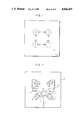
- FIG. 1 schematically illustrates one embodiment of the present invention
- FIG. 2 is a schematic circuit diagram in stripline of a feeding network for the array
- FIG. 3 illustrates the structure of one of plural EMCP's used in the array
- FIG. 4 shows the return loss of the EMCP in graphic form
- FIG. 5 illustrates the relationship of the patch diameters, resonant frequencies and the separation
- FIG. 6 illustrates the relationship between separation and bandwidth vs. return loss
- FIG. 7 illustrates test results of the device of FIG. 2.
- FIG. 1 illustrates one embodiment of the present invention.
- Four CP microstrip patch elements 1, 2, 3 and 4 form a CP 2 ⁇ 2 array in which the radiating elements' feed points are symmetrically located with respect to the array center.
- the array is equally excited at each feeding point with the phase shown in FIG. 1.
- the radiation from the dual-fed CP microstrip radiator is elliptically polarized in such a way that, among the two orthogonal linearly polarized components, E x and E y , the phase-lagging component is always weaker in strength than the phase-leading component. While E x generated by elements 1 and 3 in FIG. 1 is stronger than E y , the difference is balanced by radiation from elements 2 and 4, which radiate stronger E y than E x . The averaging effect thus leads to circular polarization of high purity.
- the invention may be easily produced using electromagnetically-coupled patchs (EMCPs) as a broadband microstrip radiator.
- EMCPs electromagnetically-coupled patchs
- FIG. 3 illustrates the structure of the EMCPs used in the invention.
- the antenna element consists of two circular patches of diameters D f and D r separated by a distance S.
- the top patch 11 (the radiating patch) is excited by the bottom patch 12 (the feeding patch), which is, in turn, fed by a coaxial line 14 from underneath, or by a microstrip line in the same plane as the feeding patch.
- the coaxial probe feed method is preferrable because it allows more flexibility in the feed network layout and separates the design of the feed network from that of the array.
- Commercially available copper-clad laminates 16, 18 (3M Cu-clad 250 LX-0300-45) were used to fabricate both the radiating and feeding patches, thus fixing the spacing between the feed patch and the ground plane.
- the radiating patch is etched beneath the top substrate 16, which also serves as a protective cover for the antenna element.
- the space between the two patches 11, 12 is filled with foam material 20 to support the radiating patch and maintain the proper separation.
- the return loss of the EMCP is characterized by two resonant frequencies which vary with separation. In general, the upper resonant frequency shifts downward and the lower shifts upward when the separation increases (FIGS. 4 and 5). The relatively constant lower resonant frequency is close to that predicted by the simple cavity model if the dimensions of the feeding patch are used in the calculations.
- a specific D f and separation S determine a particular D r that will generate double resonance. The ratio of D r and D f as a function of separation approaches unity with separation, as illustrated in FIG. 5.
- the achievable bandwidth of the EMCP depends on VSWR specifications.
- S of 0.572 cm
- the operation band for 1.22:1 VSWR is 4.01-4.47 GHz (a 10.8 percent bandwidth) while the operation band for 1.92:1 VSWR is 3.85-4.58 GHz (a 17.3-percent bandwidth).
- the operation band can be expanded to achieve a 20.4 percent bandwidth (3.82-4.69 GHz) by reducing the separation to 0.445 cm.
- Bandwidth vs return loss for four different separations is given in FIG. 6.
- the gan of an EMCP designed for 10-percent bandwidth was measured to be 7.9 dB at 4.25 GHz with a 3-dB beamwidth of approximately 90°.
- the EMCP has a generally wider bandwidth, broader beamwidth, smaller diameter (23-percent smaller), and lower cross-polarization level than a conventional patch fabricated on a thick, low dielectric substrate.
- Two features characteristic of the EMCP radiation pattern are a small gain variation within ⁇ 10° (less than 0.5 dB) and almost equal E- and H-plane patterns. The former helps minimize scan loss in a phased array, and the latter implies that the EMCP is a good CP radiator.
- CP is obtained by exciting two orthogonal modes with equal amplitude and in-phase quadrature.
- the EMCP when fed at two points (such as points A and B in FIG. 1), the EMCP generates highly elliptical polarization because of the asymmetrical feed structure.
- the asymmetry must be corrected or compensated for.
- FIG. 2 shows the circuit layout of the feeding network used in the invention.
- the network is fabricated in microstrip line on copper-clad teflon/glass laminate 21 (3M Cu-clad 250 LX-0300-45) and connected to the feeding patches of array elements 1-4 via coaxial feedthrough (such as at 14 in FIG. 3) for convenience in testing.
- the feeding network can be constructed in stripline right underneath the subarray and may share the common ground plane with the subarray. This will reduce feed line loss and avoid radiation from the unshielded line.
- another layer of stripline circuit can be constructed beneath the first layer stripline circuit.
- the second layer stripline which would consist of a duplication of only that part of the circuit inside the dashed lines 22 in FIG. 2, provides a 4-way power split with 90° phase progression, and would be connected at its outputs to the second input ports of the four branch line hybrids beneath the feeding patches on the first layer stripline feeding network.
- Test results of the device of FIG. 2 are given in FIG. 7.
- the axial ratio is below 1.0 dB, and the gain is maintained constant in the frequency band of 4.0 to 4.6 GHz (a 14-percent bandwidth). Even the stringent requirement of 0.5-dB axial ratio can be achieved in the frequency band of 4.1 to 4.4 GHz (a 7 percent bandwidth).
Abstract
Description
Claims (13)
Priority Applications (1)
| Application Number | Priority Date | Filing Date | Title |
|---|---|---|---|
| US06/623,877 US4866451A (en) | 1984-06-25 | 1984-06-25 | Broadband circular polarization arrangement for microstrip array antenna |
Applications Claiming Priority (1)
| Application Number | Priority Date | Filing Date | Title |
|---|---|---|---|
| US06/623,877 US4866451A (en) | 1984-06-25 | 1984-06-25 | Broadband circular polarization arrangement for microstrip array antenna |
Publications (1)
| Publication Number | Publication Date |
|---|---|
| US4866451A true US4866451A (en) | 1989-09-12 |
Family
ID=24499754
Family Applications (1)
| Application Number | Title | Priority Date | Filing Date |
|---|---|---|---|
| US06/623,877 Expired - Lifetime US4866451A (en) | 1984-06-25 | 1984-06-25 | Broadband circular polarization arrangement for microstrip array antenna |
Country Status (1)
| Country | Link |
|---|---|
| US (1) | US4866451A (en) |
Cited By (52)
| Publication number | Priority date | Publication date | Assignee | Title |
|---|---|---|---|---|
| EP0432647A2 (en) * | 1989-12-11 | 1991-06-19 | Kabushiki Kaisha Toyota Chuo Kenkyusho | Mobile antenna system |
| EP0449492A1 (en) * | 1990-03-28 | 1991-10-02 | Hughes Aircraft Company | Patch antenna with polarization uniformity control |
| EP0507307A2 (en) * | 1991-04-05 | 1992-10-07 | Ball Corporation | Broadband circular polarization satellite antenna |
| US5165109A (en) * | 1989-01-19 | 1992-11-17 | Trimble Navigation | Microwave communication antenna |
| US5181042A (en) * | 1988-05-13 | 1993-01-19 | Yagi Antenna Co., Ltd. | Microstrip array antenna |
| US5229782A (en) * | 1991-07-19 | 1993-07-20 | Conifer Corporation | Stacked dual dipole MMDS feed |
| US5453752A (en) * | 1991-05-03 | 1995-09-26 | Georgia Tech Research Corporation | Compact broadband microstrip antenna |
| US5594461A (en) * | 1993-09-24 | 1997-01-14 | Rockwell International Corp. | Low loss quadrature matching network for quadrifilar helix antenna |
| US5661494A (en) * | 1995-03-24 | 1997-08-26 | The United States Of America As Represented By The Administrator Of The National Aeronautics And Space Administration | High performance circularly polarized microstrip antenna |
| WO1997038465A1 (en) * | 1996-04-03 | 1997-10-16 | Johan Granholm | Dual polarization antenna array with very low cross polarization and low side lobes |
| ES2122937A1 (en) * | 1997-04-29 | 1998-12-16 | Rymsa | Aerial with two polarizations. |
| FR2772991A1 (en) * | 1997-12-19 | 1999-06-25 | Thomson Csf | Fixed antenna for global mobile communications system |
| US6078297A (en) * | 1998-03-25 | 2000-06-20 | The Boeing Company | Compact dual circularly polarized waveguide radiating element |
| US6126453A (en) * | 1998-10-08 | 2000-10-03 | Andrew Corporation | Transmission line terminations and junctions |
| US6150981A (en) * | 1998-04-02 | 2000-11-21 | Kyocera Corporation | Plane antenna, and portable radio using thereof |
| US6288677B1 (en) | 1999-11-23 | 2001-09-11 | The United States Of America As Represented By The Administrator Of The National Aeronautics And Space Administration | Microstrip patch antenna and method |
| EP1168492A1 (en) * | 2000-06-27 | 2002-01-02 | Toko, Inc. | A plane antenna |
| WO2002089248A1 (en) * | 2001-04-30 | 2002-11-07 | Mission Telecom, Inc. | A broadband dual-polarized microstrip array antenna |
| US6778144B2 (en) | 2002-07-02 | 2004-08-17 | Raytheon Company | Antenna |
| EP1450437A1 (en) * | 2003-02-24 | 2004-08-25 | Ascom Systec AG | Ring-shaped embedded antenna |
| US20040164908A1 (en) * | 2001-06-28 | 2004-08-26 | Rainer Pietig | Phased array antenna |
| EP1564843A1 (en) * | 2004-02-11 | 2005-08-17 | Sony International (Europe) GmbH | Circular polarised array antenna |
| US20050200531A1 (en) * | 2004-02-11 | 2005-09-15 | Kao-Cheng Huang | Circular polarised array antenna |
| US20050243005A1 (en) * | 2004-04-27 | 2005-11-03 | Gholamreza Rafi | Low profile hybrid phased array antenna system configuration and element |
| US20060244663A1 (en) * | 2005-04-29 | 2006-11-02 | Vulcan Portals, Inc. | Compact, multi-element antenna and method |
| US20060258315A1 (en) * | 2005-05-13 | 2006-11-16 | Go Networks, Inc | Method and device for adjacent channels operation |
| US20060256013A1 (en) * | 2005-05-13 | 2006-11-16 | Go Networks, Inc | Highly isolated circular polarized antenna |
| US20100128670A1 (en) * | 2008-11-27 | 2010-05-27 | Kuang Sheng Yun Ltd. | Base station interference-free antenna module and WiFi base station mesh network system using the antenna module |
| WO2012143179A1 (en) * | 2011-04-20 | 2012-10-26 | Robert Bosch Gmbh | Antenna device |
| US20140176389A1 (en) * | 2012-12-21 | 2014-06-26 | Htc Corporation | Small-size antenna system with adjustable polarization |
| US20140253378A1 (en) * | 2013-03-07 | 2014-09-11 | Brian L. Hinman | Quad-Sector Antenna Using Circular Polarization |
| US20150002335A1 (en) * | 2013-06-28 | 2015-01-01 | Mimosa Networks, Inc. | Ellipticity reduction in circularly polarized array antennas |
| CN105186140A (en) * | 2015-09-18 | 2015-12-23 | 西安电子科技大学 | Miniature wide beam dual polarization microstrip antenna |
| US9391375B1 (en) | 2013-09-27 | 2016-07-12 | The United States Of America As Represented By The Secretary Of The Navy | Wideband planar reconfigurable polarization antenna array |
| CN106299643A (en) * | 2016-08-10 | 2017-01-04 | 西安电子科技大学 | A kind of wideband dual polarized beam antenna of small-sized low section for mobile communication |
| US9693388B2 (en) | 2013-05-30 | 2017-06-27 | Mimosa Networks, Inc. | Wireless access points providing hybrid 802.11 and scheduled priority access communications |
| US9780892B2 (en) | 2014-03-05 | 2017-10-03 | Mimosa Networks, Inc. | System and method for aligning a radio using an automated audio guide |
| US9843940B2 (en) | 2013-03-08 | 2017-12-12 | Mimosa Networks, Inc. | System and method for dual-band backhaul radio |
| US9871302B2 (en) | 2013-03-06 | 2018-01-16 | Mimosa Networks, Inc. | Enclosure for radio, parabolic dish antenna, and side lobe shields |
| US9888485B2 (en) | 2014-01-24 | 2018-02-06 | Mimosa Networks, Inc. | Channel optimization in half duplex communications systems |
| US20180062255A1 (en) * | 2015-02-17 | 2018-03-01 | Robert Bosch Gmbh | Antenna system and method for manufacturing an antenna system |
| US9930592B2 (en) | 2013-02-19 | 2018-03-27 | Mimosa Networks, Inc. | Systems and methods for directing mobile device connectivity |
| US9986565B2 (en) | 2013-02-19 | 2018-05-29 | Mimosa Networks, Inc. | WiFi management interface for microwave radio and reset to factory defaults |
| US9998246B2 (en) | 2014-03-13 | 2018-06-12 | Mimosa Networks, Inc. | Simultaneous transmission on shared channel |
| US10096933B2 (en) | 2013-03-06 | 2018-10-09 | Mimosa Networks, Inc. | Waterproof apparatus for cables and cable interfaces |
| US10511074B2 (en) | 2018-01-05 | 2019-12-17 | Mimosa Networks, Inc. | Higher signal isolation solutions for printed circuit board mounted antenna and waveguide interface |
| US10749263B2 (en) | 2016-01-11 | 2020-08-18 | Mimosa Networks, Inc. | Printed circuit board mounted antenna and waveguide interface |
| US10958332B2 (en) | 2014-09-08 | 2021-03-23 | Mimosa Networks, Inc. | Wi-Fi hotspot repeater |
| US11069986B2 (en) | 2018-03-02 | 2021-07-20 | Airspan Ip Holdco Llc | Omni-directional orthogonally-polarized antenna system for MIMO applications |
| US11251539B2 (en) | 2016-07-29 | 2022-02-15 | Airspan Ip Holdco Llc | Multi-band access point antenna array |
| US11289821B2 (en) | 2018-09-11 | 2022-03-29 | Air Span Ip Holdco Llc | Sector antenna systems and methods for providing high gain and high side-lobe rejection |
| US11355861B2 (en) * | 2018-10-01 | 2022-06-07 | KYOCERA AVX Components (San Diego), Inc. | Patch antenna array system |
Citations (4)
| Publication number | Priority date | Publication date | Assignee | Title |
|---|---|---|---|---|
| US3921177A (en) * | 1973-04-17 | 1975-11-18 | Ball Brothers Res Corp | Microstrip antenna structures and arrays |
| US4477813A (en) * | 1982-08-11 | 1984-10-16 | Ball Corporation | Microstrip antenna system having nonconductively coupled feedline |
| US4543579A (en) * | 1983-03-29 | 1985-09-24 | Radio Research Laboratories, Ministry Of Posts And Telecommunications | Circular polarization antenna |
| US4554549A (en) * | 1983-09-19 | 1985-11-19 | Raytheon Company | Microstrip antenna with circular ring |
-
1984
- 1984-06-25 US US06/623,877 patent/US4866451A/en not_active Expired - Lifetime
Patent Citations (4)
| Publication number | Priority date | Publication date | Assignee | Title |
|---|---|---|---|---|
| US3921177A (en) * | 1973-04-17 | 1975-11-18 | Ball Brothers Res Corp | Microstrip antenna structures and arrays |
| US4477813A (en) * | 1982-08-11 | 1984-10-16 | Ball Corporation | Microstrip antenna system having nonconductively coupled feedline |
| US4543579A (en) * | 1983-03-29 | 1985-09-24 | Radio Research Laboratories, Ministry Of Posts And Telecommunications | Circular polarization antenna |
| US4554549A (en) * | 1983-09-19 | 1985-11-19 | Raytheon Company | Microstrip antenna with circular ring |
Cited By (92)
| Publication number | Priority date | Publication date | Assignee | Title |
|---|---|---|---|---|
| US5181042A (en) * | 1988-05-13 | 1993-01-19 | Yagi Antenna Co., Ltd. | Microstrip array antenna |
| US5165109A (en) * | 1989-01-19 | 1992-11-17 | Trimble Navigation | Microwave communication antenna |
| EP0432647A2 (en) * | 1989-12-11 | 1991-06-19 | Kabushiki Kaisha Toyota Chuo Kenkyusho | Mobile antenna system |
| EP0432647A3 (en) * | 1989-12-11 | 1992-01-02 | Kabushiki Kaisha Toyota Chuo Kenkyusho | Mobile antenna system |
| US5166693A (en) * | 1989-12-11 | 1992-11-24 | Kabushiki Kaisha Toyota Chuo Kenkyusho | Mobile antenna system |
| EP0449492A1 (en) * | 1990-03-28 | 1991-10-02 | Hughes Aircraft Company | Patch antenna with polarization uniformity control |
| EP0507307A3 (en) * | 1991-04-05 | 1994-09-28 | Ball Corp | Broadband circular polarization satellite antenna |
| EP0507307A2 (en) * | 1991-04-05 | 1992-10-07 | Ball Corporation | Broadband circular polarization satellite antenna |
| US5231406A (en) * | 1991-04-05 | 1993-07-27 | Ball Corporation | Broadband circular polarization satellite antenna |
| US5453752A (en) * | 1991-05-03 | 1995-09-26 | Georgia Tech Research Corporation | Compact broadband microstrip antenna |
| US5229782A (en) * | 1991-07-19 | 1993-07-20 | Conifer Corporation | Stacked dual dipole MMDS feed |
| US5293175A (en) * | 1991-07-19 | 1994-03-08 | Conifer Corporation | Stacked dual dipole MMDS feed |
| US5594461A (en) * | 1993-09-24 | 1997-01-14 | Rockwell International Corp. | Low loss quadrature matching network for quadrifilar helix antenna |
| US5661494A (en) * | 1995-03-24 | 1997-08-26 | The United States Of America As Represented By The Administrator Of The National Aeronautics And Space Administration | High performance circularly polarized microstrip antenna |
| WO1997038465A1 (en) * | 1996-04-03 | 1997-10-16 | Johan Granholm | Dual polarization antenna array with very low cross polarization and low side lobes |
| US6147648A (en) * | 1996-04-03 | 2000-11-14 | Granholm; Johan | Dual polarization antenna array with very low cross polarization and low side lobes |
| ES2122937A1 (en) * | 1997-04-29 | 1998-12-16 | Rymsa | Aerial with two polarizations. |
| FR2772991A1 (en) * | 1997-12-19 | 1999-06-25 | Thomson Csf | Fixed antenna for global mobile communications system |
| EP0930668A1 (en) * | 1997-12-19 | 1999-07-21 | Thomson-Csf | GSM base station antenna |
| US6078297A (en) * | 1998-03-25 | 2000-06-20 | The Boeing Company | Compact dual circularly polarized waveguide radiating element |
| US6150981A (en) * | 1998-04-02 | 2000-11-21 | Kyocera Corporation | Plane antenna, and portable radio using thereof |
| US6126453A (en) * | 1998-10-08 | 2000-10-03 | Andrew Corporation | Transmission line terminations and junctions |
| US6288677B1 (en) | 1999-11-23 | 2001-09-11 | The United States Of America As Represented By The Administrator Of The National Aeronautics And Space Administration | Microstrip patch antenna and method |
| US6407707B2 (en) | 2000-06-27 | 2002-06-18 | Toko, Inc. | Plane antenna |
| EP1168492A1 (en) * | 2000-06-27 | 2002-01-02 | Toko, Inc. | A plane antenna |
| WO2002089248A1 (en) * | 2001-04-30 | 2002-11-07 | Mission Telecom, Inc. | A broadband dual-polarized microstrip array antenna |
| US20040119645A1 (en) * | 2001-04-30 | 2004-06-24 | Lee Byung-Je | Broadband dual-polarized microstrip array antenna |
| US6956528B2 (en) | 2001-04-30 | 2005-10-18 | Mission Telecom, Inc. | Broadband dual-polarized microstrip array antenna |
| US20040164908A1 (en) * | 2001-06-28 | 2004-08-26 | Rainer Pietig | Phased array antenna |
| US7158081B2 (en) * | 2001-06-28 | 2007-01-02 | Koninklijke Philips Electronics N.V. | Phased array antenna |
| US6778144B2 (en) | 2002-07-02 | 2004-08-17 | Raytheon Company | Antenna |
| EP1450437A1 (en) * | 2003-02-24 | 2004-08-25 | Ascom Systec AG | Ring-shaped embedded antenna |
| US20050200531A1 (en) * | 2004-02-11 | 2005-09-15 | Kao-Cheng Huang | Circular polarised array antenna |
| US7212163B2 (en) | 2004-02-11 | 2007-05-01 | Sony Deutschland Gmbh | Circular polarized array antenna |
| EP1564843A1 (en) * | 2004-02-11 | 2005-08-17 | Sony International (Europe) GmbH | Circular polarised array antenna |
| US7161537B2 (en) | 2004-04-27 | 2007-01-09 | Intelwaves Technologies Ltd. | Low profile hybrid phased array antenna system configuration and element |
| US20050243005A1 (en) * | 2004-04-27 | 2005-11-03 | Gholamreza Rafi | Low profile hybrid phased array antenna system configuration and element |
| US20060244663A1 (en) * | 2005-04-29 | 2006-11-02 | Vulcan Portals, Inc. | Compact, multi-element antenna and method |
| US20060256013A1 (en) * | 2005-05-13 | 2006-11-16 | Go Networks, Inc | Highly isolated circular polarized antenna |
| US20060258315A1 (en) * | 2005-05-13 | 2006-11-16 | Go Networks, Inc | Method and device for adjacent channels operation |
| US7542752B2 (en) | 2005-05-13 | 2009-06-02 | Go Net Systems Ltd. | Method and device for adjacent channels operation |
| US7605758B2 (en) | 2005-05-13 | 2009-10-20 | Go Net Systems Ltd. | Highly isolated circular polarized antenna |
| US20100128670A1 (en) * | 2008-11-27 | 2010-05-27 | Kuang Sheng Yun Ltd. | Base station interference-free antenna module and WiFi base station mesh network system using the antenna module |
| WO2012143179A1 (en) * | 2011-04-20 | 2012-10-26 | Robert Bosch Gmbh | Antenna device |
| US20140176389A1 (en) * | 2012-12-21 | 2014-06-26 | Htc Corporation | Small-size antenna system with adjustable polarization |
| US9548526B2 (en) * | 2012-12-21 | 2017-01-17 | Htc Corporation | Small-size antenna system with adjustable polarization |
| US9930592B2 (en) | 2013-02-19 | 2018-03-27 | Mimosa Networks, Inc. | Systems and methods for directing mobile device connectivity |
| US10595253B2 (en) | 2013-02-19 | 2020-03-17 | Mimosa Networks, Inc. | Systems and methods for directing mobile device connectivity |
| US10200925B2 (en) | 2013-02-19 | 2019-02-05 | Mimosa Networks, Inc. | Systems and methods for directing mobile device connectivity |
| US10425944B2 (en) | 2013-02-19 | 2019-09-24 | Mimosa Networks, Inc. | WiFi management interface for microwave radio and reset to factory defaults |
| US9986565B2 (en) | 2013-02-19 | 2018-05-29 | Mimosa Networks, Inc. | WiFi management interface for microwave radio and reset to factory defaults |
| US10863507B2 (en) | 2013-02-19 | 2020-12-08 | Mimosa Networks, Inc. | WiFi management interface for microwave radio and reset to factory defaults |
| US10096933B2 (en) | 2013-03-06 | 2018-10-09 | Mimosa Networks, Inc. | Waterproof apparatus for cables and cable interfaces |
| US10790613B2 (en) | 2013-03-06 | 2020-09-29 | Mimosa Networks, Inc. | Waterproof apparatus for pre-terminated cables |
| US10186786B2 (en) | 2013-03-06 | 2019-01-22 | Mimosa Networks, Inc. | Enclosure for radio, parabolic dish antenna, and side lobe shields |
| US9871302B2 (en) | 2013-03-06 | 2018-01-16 | Mimosa Networks, Inc. | Enclosure for radio, parabolic dish antenna, and side lobe shields |
| US10742275B2 (en) * | 2013-03-07 | 2020-08-11 | Mimosa Networks, Inc. | Quad-sector antenna using circular polarization |
| US20140253378A1 (en) * | 2013-03-07 | 2014-09-11 | Brian L. Hinman | Quad-Sector Antenna Using Circular Polarization |
| US9843940B2 (en) | 2013-03-08 | 2017-12-12 | Mimosa Networks, Inc. | System and method for dual-band backhaul radio |
| US9949147B2 (en) | 2013-03-08 | 2018-04-17 | Mimosa Networks, Inc. | System and method for dual-band backhaul radio |
| US10257722B2 (en) | 2013-03-08 | 2019-04-09 | Mimosa Networks, Inc. | System and method for dual-band backhaul radio |
| US10812994B2 (en) | 2013-03-08 | 2020-10-20 | Mimosa Networks, Inc. | System and method for dual-band backhaul radio |
| US10117114B2 (en) | 2013-03-08 | 2018-10-30 | Mimosa Networks, Inc. | System and method for dual-band backhaul radio |
| US10785608B2 (en) | 2013-05-30 | 2020-09-22 | Mimosa Networks, Inc. | Wireless access points providing hybrid 802.11 and scheduled priority access communications |
| US9693388B2 (en) | 2013-05-30 | 2017-06-27 | Mimosa Networks, Inc. | Wireless access points providing hybrid 802.11 and scheduled priority access communications |
| US20150002335A1 (en) * | 2013-06-28 | 2015-01-01 | Mimosa Networks, Inc. | Ellipticity reduction in circularly polarized array antennas |
| US10938110B2 (en) * | 2013-06-28 | 2021-03-02 | Mimosa Networks, Inc. | Ellipticity reduction in circularly polarized array antennas |
| US11482789B2 (en) | 2013-06-28 | 2022-10-25 | Airspan Ip Holdco Llc | Ellipticity reduction in circularly polarized array antennas |
| US9391375B1 (en) | 2013-09-27 | 2016-07-12 | The United States Of America As Represented By The Secretary Of The Navy | Wideband planar reconfigurable polarization antenna array |
| US10616903B2 (en) | 2014-01-24 | 2020-04-07 | Mimosa Networks, Inc. | Channel optimization in half duplex communications systems |
| US9888485B2 (en) | 2014-01-24 | 2018-02-06 | Mimosa Networks, Inc. | Channel optimization in half duplex communications systems |
| US9780892B2 (en) | 2014-03-05 | 2017-10-03 | Mimosa Networks, Inc. | System and method for aligning a radio using an automated audio guide |
| US10090943B2 (en) | 2014-03-05 | 2018-10-02 | Mimosa Networks, Inc. | System and method for aligning a radio using an automated audio guide |
| US9998246B2 (en) | 2014-03-13 | 2018-06-12 | Mimosa Networks, Inc. | Simultaneous transmission on shared channel |
| US10447417B2 (en) | 2014-03-13 | 2019-10-15 | Mimosa Networks, Inc. | Synchronized transmission on shared channel |
| US11888589B2 (en) | 2014-03-13 | 2024-01-30 | Mimosa Networks, Inc. | Synchronized transmission on shared channel |
| US11626921B2 (en) | 2014-09-08 | 2023-04-11 | Airspan Ip Holdco Llc | Systems and methods of a Wi-Fi repeater device |
| US10958332B2 (en) | 2014-09-08 | 2021-03-23 | Mimosa Networks, Inc. | Wi-Fi hotspot repeater |
| US20180062255A1 (en) * | 2015-02-17 | 2018-03-01 | Robert Bosch Gmbh | Antenna system and method for manufacturing an antenna system |
| US10468764B2 (en) * | 2015-02-17 | 2019-11-05 | Robert Bosch Gmbh | Antenna system and method for manufacturing an antenna system |
| CN105186140A (en) * | 2015-09-18 | 2015-12-23 | 西安电子科技大学 | Miniature wide beam dual polarization microstrip antenna |
| CN105186140B (en) * | 2015-09-18 | 2018-06-08 | 西安电子科技大学 | A kind of small-sized broad beam double polarized micro strip antenna |
| US10749263B2 (en) | 2016-01-11 | 2020-08-18 | Mimosa Networks, Inc. | Printed circuit board mounted antenna and waveguide interface |
| US11251539B2 (en) | 2016-07-29 | 2022-02-15 | Airspan Ip Holdco Llc | Multi-band access point antenna array |
| CN106299643A (en) * | 2016-08-10 | 2017-01-04 | 西安电子科技大学 | A kind of wideband dual polarized beam antenna of small-sized low section for mobile communication |
| US10714805B2 (en) | 2018-01-05 | 2020-07-14 | Milmosa Networks, Inc. | Higher signal isolation solutions for printed circuit board mounted antenna and waveguide interface |
| US10511074B2 (en) | 2018-01-05 | 2019-12-17 | Mimosa Networks, Inc. | Higher signal isolation solutions for printed circuit board mounted antenna and waveguide interface |
| US11069986B2 (en) | 2018-03-02 | 2021-07-20 | Airspan Ip Holdco Llc | Omni-directional orthogonally-polarized antenna system for MIMO applications |
| US11404796B2 (en) | 2018-03-02 | 2022-08-02 | Airspan Ip Holdco Llc | Omni-directional orthogonally-polarized antenna system for MIMO applications |
| US11637384B2 (en) | 2018-03-02 | 2023-04-25 | Airspan Ip Holdco Llc | Omni-directional antenna system and device for MIMO applications |
| US11289821B2 (en) | 2018-09-11 | 2022-03-29 | Air Span Ip Holdco Llc | Sector antenna systems and methods for providing high gain and high side-lobe rejection |
| US11355861B2 (en) * | 2018-10-01 | 2022-06-07 | KYOCERA AVX Components (San Diego), Inc. | Patch antenna array system |
Similar Documents
| Publication | Publication Date | Title |
|---|---|---|
| US4866451A (en) | Broadband circular polarization arrangement for microstrip array antenna | |
| US5231406A (en) | Broadband circular polarization satellite antenna | |
| US4929959A (en) | Dual-polarized printed circuit antenna having its elements capacitively coupled to feedlines | |
| US4843400A (en) | Aperture coupled circular polarization antenna | |
| US4737793A (en) | Radio frequency antenna with controllably variable dual orthogonal polarization | |
| US6147648A (en) | Dual polarization antenna array with very low cross polarization and low side lobes | |
| US6545647B1 (en) | Antenna system for communicating simultaneously with a satellite and a terrestrial system | |
| EP0342175B1 (en) | Dual-polarized printed circuit antenna having its elements, including gridded printed circuit elements, capacitively coupled to feedlines | |
| US5005019A (en) | Electromagnetically coupled printed-circuit antennas having patches or slots capacitively coupled to feedlines | |
| US8537068B2 (en) | Method and apparatus for tri-band feed with pseudo-monopulse tracking | |
| US4973972A (en) | Stripline feed for a microstrip array of patch elements with teardrop shaped probes | |
| EP0516440B1 (en) | Microstrip antenna | |
| US10283876B1 (en) | Dual-polarized, planar slot-aperture antenna element | |
| US6690331B2 (en) | Beamforming quad meanderline loaded antenna | |
| US6741210B2 (en) | Dual band printed antenna | |
| US20210028556A1 (en) | Multi-port multi-beam antenna system on printed circuit board with low correlation for mimo applications and method therefor | |
| EP1018778B1 (en) | Multi-layered patch antenna | |
| US11539146B2 (en) | Circular polarized phased array with wideband axial ratio bandwidth using sequential rotation and dynamic phase recovery | |
| Rohrdantz et al. | Ka-band antenna arrays with dual-frequency and dual-polarized patch elements | |
| Głogowski et al. | Circularly polarized aperture coupled stacked patch antenna element for Ka-band | |
| US4660047A (en) | Microstrip antenna with resonator feed | |
| Liu et al. | Polarization and Bandwidth Reconfigurable Rectangular Dielectric Resonator Antenna | |
| JPH06237119A (en) | Shared plane antenna for polarized waves | |
| Rahman et al. | A multi-layer approach of orthogonally fed circularly polarized microstrip array antenna for enhanced gain | |
| Bezousek et al. | Dual frequency band integrated antenna array |
Legal Events
| Date | Code | Title | Description |
|---|---|---|---|
| AS | Assignment |
Owner name: COMMUNICATIONS SATELLITE CORPORATION, DISTRICT OF Free format text: ASSIGNMENT OF ASSIGNORS INTEREST.;ASSIGNOR:CHEN, CHUN-HONG H.;REEL/FRAME:005134/0815 Effective date: 19890721 |
|
| STCF | Information on status: patent grant |
Free format text: PATENTED CASE |
|
| FEPP | Fee payment procedure |
Free format text: PAYOR NUMBER ASSIGNED (ORIGINAL EVENT CODE: ASPN); ENTITY STATUS OF PATENT OWNER: LARGE ENTITY |
|
| FPAY | Fee payment |
Year of fee payment: 4 |
|
| AS | Assignment |
Owner name: COMSAT CORPORATION, MARYLAND Free format text: CHANGE OF NAME;ASSIGNOR:COMMUNICATIONS SATELLITE CORPORATION;REEL/FRAME:006711/0455 Effective date: 19930524 |
|
| FEPP | Fee payment procedure |
Free format text: PAYER NUMBER DE-ASSIGNED (ORIGINAL EVENT CODE: RMPN); ENTITY STATUS OF PATENT OWNER: LARGE ENTITY Free format text: PAYOR NUMBER ASSIGNED (ORIGINAL EVENT CODE: ASPN); ENTITY STATUS OF PATENT OWNER: LARGE ENTITY |
|
| FPAY | Fee payment |
Year of fee payment: 8 |
|
| REMI | Maintenance fee reminder mailed | ||
| FPAY | Fee payment |
Year of fee payment: 12 |
|
| SULP | Surcharge for late payment |
Year of fee payment: 11 |