US4873045A - Method for manufacturing automotive interior components - Google Patents
Method for manufacturing automotive interior components Download PDFInfo
- Publication number
- US4873045A US4873045A US07/172,407 US17240788A US4873045A US 4873045 A US4873045 A US 4873045A US 17240788 A US17240788 A US 17240788A US 4873045 A US4873045 A US 4873045A
- Authority
- US
- United States
- Prior art keywords
- mold
- layer
- skin layer
- core
- automotive interior
- Prior art date
- Legal status (The legal status is an assumption and is not a legal conclusion. Google has not performed a legal analysis and makes no representation as to the accuracy of the status listed.)
- Expired - Fee Related
Links
Images


Classifications
-
- B—PERFORMING OPERATIONS; TRANSPORTING
- B29—WORKING OF PLASTICS; WORKING OF SUBSTANCES IN A PLASTIC STATE IN GENERAL
- B29C—SHAPING OR JOINING OF PLASTICS; SHAPING OF MATERIAL IN A PLASTIC STATE, NOT OTHERWISE PROVIDED FOR; AFTER-TREATMENT OF THE SHAPED PRODUCTS, e.g. REPAIRING
- B29C31/00—Handling, e.g. feeding of the material to be shaped, storage of plastics material before moulding; Automation, i.e. automated handling lines in plastics processing plants, e.g. using manipulators or robots
- B29C31/04—Feeding of the material to be moulded, e.g. into a mould cavity
- B29C31/042—Feeding of the material to be moulded, e.g. into a mould cavity using dispensing heads, e.g. extruders, placed over or apart from the moulds
- B29C31/044—Feeding of the material to be moulded, e.g. into a mould cavity using dispensing heads, e.g. extruders, placed over or apart from the moulds with moving heads for distributing liquid or viscous material into the moulds
-
- B—PERFORMING OPERATIONS; TRANSPORTING
- B29—WORKING OF PLASTICS; WORKING OF SUBSTANCES IN A PLASTIC STATE IN GENERAL
- B29C—SHAPING OR JOINING OF PLASTICS; SHAPING OF MATERIAL IN A PLASTIC STATE, NOT OTHERWISE PROVIDED FOR; AFTER-TREATMENT OF THE SHAPED PRODUCTS, e.g. REPAIRING
- B29C43/00—Compression moulding, i.e. applying external pressure to flow the moulding material; Apparatus therefor
- B29C43/02—Compression moulding, i.e. applying external pressure to flow the moulding material; Apparatus therefor of articles of definite length, i.e. discrete articles
- B29C43/18—Compression moulding, i.e. applying external pressure to flow the moulding material; Apparatus therefor of articles of definite length, i.e. discrete articles incorporating preformed parts or layers, e.g. compression moulding around inserts or for coating articles
- B29C43/183—Compression moulding, i.e. applying external pressure to flow the moulding material; Apparatus therefor of articles of definite length, i.e. discrete articles incorporating preformed parts or layers, e.g. compression moulding around inserts or for coating articles the preformed layer being a lining, e.g. shaped in the mould before compression moulding, or a preformed shell adapted to the shape of the mould
-
- B—PERFORMING OPERATIONS; TRANSPORTING
- B29—WORKING OF PLASTICS; WORKING OF SUBSTANCES IN A PLASTIC STATE IN GENERAL
- B29C—SHAPING OR JOINING OF PLASTICS; SHAPING OF MATERIAL IN A PLASTIC STATE, NOT OTHERWISE PROVIDED FOR; AFTER-TREATMENT OF THE SHAPED PRODUCTS, e.g. REPAIRING
- B29C43/00—Compression moulding, i.e. applying external pressure to flow the moulding material; Apparatus therefor
- B29C43/02—Compression moulding, i.e. applying external pressure to flow the moulding material; Apparatus therefor of articles of definite length, i.e. discrete articles
- B29C43/20—Making multilayered or multicoloured articles
- B29C43/203—Making multilayered articles
-
- B—PERFORMING OPERATIONS; TRANSPORTING
- B29—WORKING OF PLASTICS; WORKING OF SUBSTANCES IN A PLASTIC STATE IN GENERAL
- B29C—SHAPING OR JOINING OF PLASTICS; SHAPING OF MATERIAL IN A PLASTIC STATE, NOT OTHERWISE PROVIDED FOR; AFTER-TREATMENT OF THE SHAPED PRODUCTS, e.g. REPAIRING
- B29C48/00—Extrusion moulding, i.e. expressing the moulding material through a die or nozzle which imparts the desired form; Apparatus therefor
- B29C48/25—Component parts, details or accessories; Auxiliary operations
- B29C48/36—Means for plasticising or homogenising the moulding material or forcing it through the nozzle or die
- B29C48/50—Details of extruders
-
- B—PERFORMING OPERATIONS; TRANSPORTING
- B29—WORKING OF PLASTICS; WORKING OF SUBSTANCES IN A PLASTIC STATE IN GENERAL
- B29C—SHAPING OR JOINING OF PLASTICS; SHAPING OF MATERIAL IN A PLASTIC STATE, NOT OTHERWISE PROVIDED FOR; AFTER-TREATMENT OF THE SHAPED PRODUCTS, e.g. REPAIRING
- B29C70/00—Shaping composites, i.e. plastics material comprising reinforcements, fillers or preformed parts, e.g. inserts
- B29C70/68—Shaping composites, i.e. plastics material comprising reinforcements, fillers or preformed parts, e.g. inserts by incorporating or moulding on preformed parts, e.g. inserts or layers, e.g. foam blocks
- B29C70/78—Moulding material on one side only of the preformed part
-
- B—PERFORMING OPERATIONS; TRANSPORTING
- B29—WORKING OF PLASTICS; WORKING OF SUBSTANCES IN A PLASTIC STATE IN GENERAL
- B29C—SHAPING OR JOINING OF PLASTICS; SHAPING OF MATERIAL IN A PLASTIC STATE, NOT OTHERWISE PROVIDED FOR; AFTER-TREATMENT OF THE SHAPED PRODUCTS, e.g. REPAIRING
- B29C48/00—Extrusion moulding, i.e. expressing the moulding material through a die or nozzle which imparts the desired form; Apparatus therefor
- B29C48/03—Extrusion moulding, i.e. expressing the moulding material through a die or nozzle which imparts the desired form; Apparatus therefor characterised by the shape of the extruded material at extrusion
- B29C48/07—Flat, e.g. panels
- B29C48/08—Flat, e.g. panels flexible, e.g. films
-
- B—PERFORMING OPERATIONS; TRANSPORTING
- B29—WORKING OF PLASTICS; WORKING OF SUBSTANCES IN A PLASTIC STATE IN GENERAL
- B29K—INDEXING SCHEME ASSOCIATED WITH SUBCLASSES B29B, B29C OR B29D, RELATING TO MOULDING MATERIALS OR TO MATERIALS FOR MOULDS, REINFORCEMENTS, FILLERS OR PREFORMED PARTS, e.g. INSERTS
- B29K2105/00—Condition, form or state of moulded material or of the material to be shaped
- B29K2105/25—Solid
- B29K2105/253—Preform
- B29K2105/256—Sheets, plates, blanks or films
-
- B—PERFORMING OPERATIONS; TRANSPORTING
- B29—WORKING OF PLASTICS; WORKING OF SUBSTANCES IN A PLASTIC STATE IN GENERAL
- B29L—INDEXING SCHEME ASSOCIATED WITH SUBCLASS B29C, RELATING TO PARTICULAR ARTICLES
- B29L2009/00—Layered products
-
- B—PERFORMING OPERATIONS; TRANSPORTING
- B29—WORKING OF PLASTICS; WORKING OF SUBSTANCES IN A PLASTIC STATE IN GENERAL
- B29L—INDEXING SCHEME ASSOCIATED WITH SUBCLASS B29C, RELATING TO PARTICULAR ARTICLES
- B29L2031/00—Other particular articles
- B29L2031/30—Vehicles, e.g. ships or aircraft, or body parts thereof
- B29L2031/3005—Body finishings
- B29L2031/3041—Trim panels
Definitions
- the present invention relates to automotive interior component parts such as automotive door trims, rear side trims, rear parcel shelves, etc., and in particular to a method for manufacturing automotive interior component parts in which a skin layer and a core layer are integrally press formed into an interior component part having a certain shape.
- Automotive interior components such as automotive door trims, rear side trims, rear parcel shelves, etc. are typically provided with a layered structure comprising a core layer having a certain rigidity and a skin layer having an ornamental or attractive surface texture which is bonded to the surface of the core layer.
- a layered structure comprising a core layer having a certain rigidity and a skin layer having an ornamental or attractive surface texture which is bonded to the surface of the core layer.
- an interior component part of a desired shape was obtained by softening a thermoplastic resin plate or a thermoplastic composite resin plate, serving as a core layer, by heating it, laminating a skin layer consisting of a sheet of non-woven fabric or resin material over the core layer, and cold press forming this assembly.
- an exterior sheet 1 is placed on a lower press mold 3 and blocks of thermoplastic resin material 2, for instance, consisting of polyolefin resin material or the like, are placed on the exterior sheet 1 as shown in FIG. 5.
- an upper press mold 4 is lowered over the lower press mold 3 and they are clamped together to squeeze the thermoplastic material 2 into a sheet therebetween as shown in FIG. 6.
- the exterior sheet 1 and the thermoplastic material 2 are integrally bonded together and this assembly is given a desired shape as shown in FIG. 7.
- the reverse surface of the exterior sheet 1 is typically laminated with a fibrous layer 1b' consisting of fibrous material such as a non-woven fabric lining.
- the material of the exterior sheet 1 is limited to non-porous resin sheet material such as a polyvinyl chloride sheet and, if a porous material such as cloth, carpet, non-woven fabric etc. is used, the excessive clamping pressure would cause the molten resin material to infiltrate through the space between the fibers of the exterior sheet to the external surface, thereby severely impairing the external appearance of the assembly.
- the skin layer is required to be made of non-porous material and a severe restriction is therefore imposed on material selection.
- thermoplastic resin material For press forming blocks of thermoplastic resin material into a sheet, a considerably high pressure and temperature are required so that the thermoplastic resin material tends to infiltrate through the fibrous material and, although a strong bonding may be achieved by the interlocking of the two materials, the surface of the exterior sheet 1 suffers from surface irregularities due to the infiltration of the thermoplastic resin into the space between the fibers of the exterior sheet, thus impairing the appearance and the fuel of the external surface.
- a primary object of the present invention is to reduce the time and labor required in manufacturing automotive interior components by integrally assembling a core layer and a skin layer by press forming and, in particular, to provide a method for manufacturing automotive interior components which permits the use of porous material having a soft feel, such as cloth, carpet, non-woven fabric and other fabric materials as a skin layer.
- a second object of the present invention is to provide a method for manufacturing automotive interior components which permits the use of porous material for the skin layer and offers a favorable appearance and feel.
- a third object of the present invention is to provide a method for manufacturing automotive interior components which can produce an external surface free from surface irregularities.
- a method for manufacturing automotive interior component parts comprising the steps of: positioning a skin layer, having a back liner consisting of a cushioning layer, on a mold surface of an upper mold with the cushioning layer facing downward; extruding a sheet of semi-molten thermoplastic resin material serving as a core layer directly onto a mold surface of a lower mold; clamping together the upper and the lower mold in such a manner that the core layer and the skin layer are bonded together with the cushioning layer interposed therebetween.
- the skin layer is given with a very smooth surface even when it is made of porous material such as fabric. Additionally, since the core material is directly extruded onto a core surface, the pressure and the temperature involved the press forming process may be low.
- the sheet of semi-molten thermoplastic resin material can be conveniently placed on the mold surface if an outlet of an extruder is moved relative to the mold surface in such a manner that the speed of the relative motion between the outlet of the extruder and the mold surface is substantially equal to the speed at which the sheet of semi-molten thermoplastic resin material is extruded from the outlet.
- the outlet of the extruder may consist of a die communicated with a screw extruder by way of articulated tubing.
- the skin layer may consist of porous material such as fabric.
- the cushioning layer consists of urethane foam. If the core layer is made of polyolefin resin while the cushioning layer consists of polyolefin foam, a favorable bonding can be achieved therebetween.
- automotive components of laminated structure are manufactured simply by squeezing semi-molten resin material over a mold surface of a lower mold for cold press, lowering an upper mold for cold press having skin layer set up thereto, and clamping the two parts of the mold together. Therefore, according to the present invention, a considerable advantage is obtained as compared to the conventional method in which core layer such as a thermoplastic resin plate or a thermoplastic composite resin plate is softened by heating as a separate process and setting it up on a lower mold for cold press.
- core layer such as a thermoplastic resin plate or a thermoplastic composite resin plate
- the resin material is formed into a sheet in advance and the cushion material relieves the press pressure according to the present invention
- the pressure and the temperature for the press forming process may be low and the freedom in material selection is drastically increased since the material is not limited to non-porous material but may be soft fabric material such as cloth, carpet, non-woven fabric and other materials having a soft feel.
- the cushioning material serves as a barrier against the infiltration of the molten resin, the surface of the skin layer or the surface of the final product is free from any irregularities and the feel and the appearance of the component are much improved.
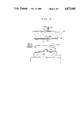
- FIG. 1 is an illustrative view showing the general structure of an embodiment of the apparatus for implementing the method of the present invention
- FIGS. 2 and 3 are sectional views of a forming mold showing different steps of the method of the present invention
- FIG. 4 is a sectional view showing an automotive door trim which is formed by the method of the present invention.
- FIGS. 5 through 7 show a prior art process, FIGS. 5 and 6 illustrating a conventional molding process while FIG. 7 is a sectional view showing a product made by this conventional molding method.
- FIG. 1 is an illustrative view showing the general structure of the device for implementing the method of the present invention
- FIGS. 2 and 3 are sectional views showing different steps of the method of the present invention
- FIG. 4 is a sectional view showing an automotive interior component part which is formed by the method of the present invention.
- the apparatus for implementing the method of the present invention generally consists of an extruder 10, a movable die unit 20 and a mold press 40.
- the extruder 10 comprises a hopper 11 for supplying pellets of thermoplastic resin material into the main part of the extruder 10. If desired, filler such as wood powder may be mixed with the thermoplastic resin material.
- This extruder includes a screw or auger unit 12 comprising a heated barrel, a single screw or auger received, and a breaker plate 13 provided at a terminal end of the barrel for feeding the material to the movable die unit 20 from an orifice provided therein.
- molten resin is supplied from the breaker plate 13 of the extruder 10 to a die 24 for supplying sheet material by way of a first through a third supply tube 21, 22 and 23.
- the die 24 and the third supply tube 23 are securely fixed to the upper surface of a movable base 25 which is in turn adapted to move relative to a fixed table 26 in the direction indicated by an arrow in FIG. 1.
- a servometer 27 is mounted to the fixed table 26 and a screw rod 28 is attached to the output shaft of the servomotor 27.
- a ball nut 29 which threads with the screw rod 28 is attached to the lower surface of the moveable base 25 by way of a bracket 30.
- the moveable base 25 moves in a reciprocating manner by a stroke which depends on the rotational speed and the rotational direction of the servomotor 27, by way of the feed screw mechanism consisting of the screw rod 28 and the ball nut 29, and the die 24 for supplying sheet material moves likewise in a reciprocating manner following the motion of the moveable base 25.
- the first supply tube 21 and the second supply tube 22 are allowed to move in the fashion of a pair of mutually pivoted links in a plane parallel to the major surface of the moveable base 25 or the fixed table 26.
- hinges 31 through 33 between adjacent ones of the supply tubes 21 through 23 in such a manner that, as a result of the motion of the first and the second supply tube 21 and 22 in the fashion of a pair of links, molten resin is continuously introduced from the breaker plate 13 to the die 24 for supplying sheet material following the reciprocating motion of the die 24 for supplying sheet material.
- the die 24 for supplying sheet material consists of a wide die which is generally called as a T-die; the molten resin is slightly chilled by this die 24 and is fed out from the tip of this die 24 as a semi-molten sheet.
- the moveable base 25 is adapted to smoothly reciprocate by means of a guide member provided in the fixed table 26.
- the mold press 40 is provided adjacent to the fixed table 26 which supports the moveable die unit 20 and is comprised of a lower cold press mold 41 having a mold surface 41a of a desired contour and an upper cold press mold 42 having a similar mold surface 42a.
- the upper mold 42 is adapted to move vertically relative to the lower mold 41 by means of a drive unit such as a hydraulic cylinder unit 43.
- the die 24 moves along the mold surface of the lower cold press mold 41 between the position interposed between the upper and the lower mold 41 and 42 as indicated by a chain dot line in FIG. 1 and the position out of the space between the upper and the lower mold 41 and 42 as indicated by a solid line in FIG. 1.
- the drive unit for the moveable die 24 consisted of a ball screw mechanism using the servomotor 27 and the feed screw rod 28 in the present embodiment, but, instead, a hydraulic cylinder may be directly connected to the moveable die 24 for achieving the reciprocating motion.
- a skin layer 50 consisting of cloth, non-woven fabric or the like is set up on the mold surface 42a of the upper cold press mold 42.
- This skin layer 50 has a laminated structure with a cushioning layer 51, such as a layer of polyurethane foam, lined to the reverse surface of the skin layer 50.
- thermoplastic resin a mixture of polyolefin resin and wood powder filler at a suitable ratio is melted in the extruder 10 by heating and the molten thermoplastic resin, introduced into the die 24 by way of the first through the third articulated supply tubes 21, 22 and 23, is slightly chilled before it is finally extruded onto the mold surface 41 of the lower cold press mold 41a in the form of semi-molten sheet material.
- This semi-molten sheet of thermoplastic resin serves as the core layer 52.
- the upper cold press mold 42 is lowered over the lower mold 41 and, by clamping together the two parts of the mold, a sheet of the core layer 52 is press formed into the shape given by the mold surfaces 41a and 42a of the press mold while the skin layer 50 is integrally bonded to the core layer 52 with the cushion layer 51 interposed therebetween.
- the upper cold press mold 42 is lifted by the action of the hydraulic cylinder 43 and a door trim 53 formed into a desired shape may now be taken out from the lower mold 41 as shown in FIG. 4.
- the skin layer 50 comprises a back lining of cushion layer 51 such as polyurethane foam laminated to the reverse surface of the skin layer and this cushion layer 51 serves as a barrier for preventing the infiltration of the core layer 52 to the external surface
- the material for the skin layer may consist of porous material such as cloth, carpet, non-woven fabric as well as a resin sheet consisting of polyvinyl chloride, polyvinyl chloride foam or the like, thus eliminating the limitations on the material selection.
- the temperatures of the metallic cold press molds 41 and 42 and the die 24 for supplying sheet material may be from room temperature to 60° C. and from 160° C. to 180° C., respectively, while the press pressure may be from 30 to 50 kg/cm 2 .
- the temperatures and the pressure involved are so low the skin layer 50 would not suffer from unfavorable influences from the press pressure and the temperature.
- the bonding between the core layer 52 and the skin layer 50 is accomplished by the molten resin infiltrating into the minute cells of the cushion layer consisting of a layer of polyurethane foam, an anchoring action is produced for secure bonding therebetween. Furthermore, since the thickness of the cushion layer 51 contributes to the elimination of the surface irregularities of the skin layer 50 and the cushion layer 51, it additionally serves as a barrier for preventing the semi-molten resin for the core layer 52 from infiltrating to the skin layer 50, and the appearance and the feel of the surface of the product are much improved.
- the material of the cushion layer 51 is selected to be polyolefin foam when the core layer is made of polyolefin resin as was the case in the present embodiment, an even stronger bonding can be accomplished due to the strong affinity therebetween in addition to the anchoring action mentioned earlier.
- both the press pressure and the mold temperature may be low, unfavorable influences of heat and pressure to the skin layer are eliminated.
- the cushioning layer which is laminated to the reverse surface of the skin layer uniformly distributes the press pessure over the entire surface of the skin layer, and the cushion layer serves as a barrier for preventing the infiltration of the molten resin forming the core layer to the skin layer, a satisfactory finish of the external surface of the skin layer is assured.
- the manufacturing process is simplified on the one hand while a greater freedom in material selection is accomplished and the appearance and the feel of the products are improved on the other hand.
Abstract
Description
Claims (4)
Applications Claiming Priority (2)
| Application Number | Priority Date | Filing Date | Title |
|---|---|---|---|
| JP62-175460 | 1987-07-14 | ||
| JP17546087A JPS6418622A (en) | 1987-07-14 | 1987-07-14 | Manufacture of interior trim for automobile |
Publications (1)
| Publication Number | Publication Date |
|---|---|
| US4873045A true US4873045A (en) | 1989-10-10 |
Family
ID=15996453
Family Applications (1)
| Application Number | Title | Priority Date | Filing Date |
|---|---|---|---|
| US07/172,407 Expired - Fee Related US4873045A (en) | 1987-07-14 | 1988-03-24 | Method for manufacturing automotive interior components |
Country Status (3)
| Country | Link |
|---|---|
| US (1) | US4873045A (en) |
| JP (1) | JPS6418622A (en) |
| GB (1) | GB2206835B (en) |
Cited By (53)
| Publication number | Priority date | Publication date | Assignee | Title |
|---|---|---|---|---|
| US4968474A (en) * | 1988-09-19 | 1990-11-06 | Toyoda Gosei Co., Ltd. | Method of producing resin molded article |
| US5006188A (en) * | 1988-02-03 | 1991-04-09 | Honda Giken Kogyo Kabushiki Kaisha | Method for producing plastic moldings |
| DE4101106A1 (en) * | 1991-01-16 | 1992-07-23 | Krauss Maffei Ag | METHOD AND DEVICE FOR PRODUCING LAMINATED MOLDED PARTS |
| US5151237A (en) * | 1990-06-11 | 1992-09-29 | Siebolt Hettinga | Method of injection molding a flat deformable laminate |
| US5196151A (en) * | 1990-09-11 | 1993-03-23 | Toyoda Gosei Co., Ltd. | Method for producing foam base material product with securing device |
| US5219893A (en) * | 1990-01-18 | 1993-06-15 | Bayer Aktiengesellschaft | Process for the production of open-cell, cold-formable rigid polyurethane foams and their use for the production of molded articles |
| US5268053A (en) * | 1990-11-28 | 1993-12-07 | The Standard Products Company | Plastic heat set molding |
| US5281383A (en) * | 1991-03-13 | 1994-01-25 | Kasai Kogyo Co., Ltd. | Method for molding a laminated molded article using a vented mold |
| US5326520A (en) * | 1993-04-29 | 1994-07-05 | General Motors Corporation | Laminating film to plastics extrudate and cornering extrudate with selected radii |
| US5328651A (en) * | 1993-03-05 | 1994-07-12 | Davidson Textron Inc. | Method for manufacturing an automobile trim component by blow molding and injection molding |
| US5395579A (en) * | 1992-02-28 | 1995-03-07 | Kinugawa Rubber Ind. Co., Ltd. | Method of producing weatherstrip for automotive vehicle |
| US5462786A (en) * | 1991-03-22 | 1995-10-31 | Asaa Technologies, Inc. | Decorative panels for automobile interiors |
| US5486329A (en) * | 1991-11-25 | 1996-01-23 | Kasai Kogyo Co., Ltd. | Automotive door trim and method for fabricating the same |
| US5543094A (en) * | 1991-10-31 | 1996-08-06 | Sumitomo Chemical Company, Limited | Method of forming a multilayer molded article |
| DE19518143C1 (en) * | 1995-05-17 | 1996-10-31 | Krauss Maffei Ag | Method and device for producing thin-walled laminated molded parts |
| US5585061A (en) * | 1991-04-25 | 1996-12-17 | Sumitomo Chemical Co., Ltd. | Method for producing a multilayer molded article |
| DE19518124C1 (en) * | 1995-05-17 | 1996-12-19 | Krauss Maffei Ag | Thermoplastic moulding unit |
| US5626382A (en) * | 1995-04-03 | 1997-05-06 | Lear Corporation | Molded plastic panel having integrated, localized soft-touch aesthetic feature |
| US5629085A (en) * | 1992-08-11 | 1997-05-13 | Toyoda Gosei Co., Ltd. | Resin laminate |
| US5635129A (en) * | 1990-05-02 | 1997-06-03 | Trienda Corporation | Twin-sheet thermoforming process with shell reinforcement |
| US5679301A (en) * | 1995-01-06 | 1997-10-21 | Ford Motor Company | Method for molding a multilayered trim component |
| US5824251A (en) * | 1992-06-29 | 1998-10-20 | Duotec Products Associates | Method for forming plastic molded panels with inserts |
| US5922265A (en) * | 1997-04-04 | 1999-07-13 | Lear Corporation | Method of forming a motor vehicle dash insulator |
| US5961902A (en) * | 1995-03-27 | 1999-10-05 | Araco Kabushiki Kaisha | Manufacturing method for molded multilayer article |
| US6050579A (en) * | 1998-04-21 | 2000-04-18 | Aeroquip Corporation | Automotive running board |
| US6096251A (en) * | 1995-12-22 | 2000-08-01 | Plastic Omnium Auto Interieur | Method and apparatus for the manufacture of a multilayered object |
| US6117384A (en) * | 1997-11-06 | 2000-09-12 | General Electric Co. | In-mold decorating process |
| US6165404A (en) * | 1990-10-24 | 2000-12-26 | Lear Corporation | Method of producing stratiform articles and products |
| US6174488B1 (en) * | 1992-10-26 | 2001-01-16 | Kasai Kogyo Co., Ltd. | Method for fabricating a laminated molded assembly |
| US6186765B1 (en) * | 1997-03-31 | 2001-02-13 | Toshiba Kikai Kabushiki Kaisha | Apparatus for forming a molded multilayer product |
| US6189589B1 (en) * | 1993-05-21 | 2001-02-20 | Kasai Kogyo Co., Ltd. | Molding method for laminated body using cooling air |
| WO2001060577A1 (en) * | 2000-02-17 | 2001-08-23 | The Elizabeth And Sandor Valyi Foundation, Inc. | Process and apparatus for preparing a molded article |
| WO2001074583A1 (en) * | 2000-03-30 | 2001-10-11 | Clarion Technologies, Inc. | Molded finished part and method of making same cross-references to related applications |
| EP1237709A1 (en) * | 1999-11-24 | 2002-09-11 | Kenneth Assink | A furniture panel and method of making |
| US6464814B2 (en) * | 1996-03-29 | 2002-10-15 | Toyoda Gosei Co., Ltd. | Method for molding an end of a long resin molded article |
| US6558146B1 (en) * | 2000-10-10 | 2003-05-06 | Delphi Technologies, Inc. | Extrusion deposition molding with in-line compounding of reinforcing fibers |
| US6572808B1 (en) * | 1998-12-17 | 2003-06-03 | Idemitsu Petrochemical Co., Ltd. | Method for producing a molded laminate |
| US6616879B1 (en) * | 1999-06-07 | 2003-09-09 | Sumitomo Chemical Company, Limited | Methods for producing multilayer molded articles |
| US20030211304A1 (en) * | 2001-03-30 | 2003-11-13 | Kenneth Assink | Molded finished part and method of making same cross-references to related applications |
| US6656397B1 (en) | 1999-03-11 | 2003-12-02 | Delphi Technologies, Inc. | Method of making a door trim assembly |
| US20040028958A1 (en) * | 2002-06-18 | 2004-02-12 | Total Innovative Manufacturing Llc | Recyclable fire-resistant moldable batt and panels formed therefrom |
| US6723263B2 (en) | 2001-09-25 | 2004-04-20 | Delphi Technologies, Inc. | Apparatus and method of making interior trim panel |
| US6838027B2 (en) * | 1999-12-30 | 2005-01-04 | Delphi Technologies, Inc. | Method of making an interior trim panel |
| US20050012234A1 (en) * | 2003-06-18 | 2005-01-20 | Kindig Alan L. | Method for making cushioned products with an integral cover |
| US20050142964A1 (en) * | 2003-12-30 | 2005-06-30 | Jean-Jacques Katz | Composite shoddy and method of manufacturing same |
| WO2005039853A3 (en) * | 2003-10-23 | 2005-12-29 | Sacmi | Compression moulding apparatus, methods and item |
| US7045206B1 (en) | 2000-07-10 | 2006-05-16 | Visteon Global Technologies, Inc. | Molded panels having a soft pad armrest |
| US20090321504A1 (en) * | 2005-01-14 | 2009-12-31 | Bradford Company | Dunnage Structure Made With Multiple Ply Partitions |
| US20100104818A1 (en) * | 2007-01-15 | 2010-04-29 | Shin Caterpillar Mitsubishi Ltd. | Panel and method for manufacturing the same |
| CN102029677A (en) * | 2009-05-22 | 2011-04-27 | 伊顿公司 | Appartus and method for forming a reminder rib in a grip |
| DE102014113227A1 (en) * | 2014-09-15 | 2016-03-17 | Faurecia Innenraum Systeme Gmbh | Method for producing a vehicle trim part |
| US11167627B2 (en) * | 2017-08-17 | 2021-11-09 | Bayerische Motoren Werke Aktiengesellschaft | Covering assembly for a motor vehicle |
| FR3123358A1 (en) | 2021-05-25 | 2022-12-02 | Vecormat Bfc | Process for the production of a composite natural material with low carbon footprint and high natural material content. |
Families Citing this family (8)
| Publication number | Priority date | Publication date | Assignee | Title |
|---|---|---|---|---|
| DE68915817T2 (en) * | 1988-03-01 | 1994-11-03 | Toray Industries | Process for making a molded laminated article. |
| EP0423676A3 (en) * | 1989-10-16 | 1992-01-08 | Sumitomo Chemical Company, Limited | Method for producing molded article of fiber-reinforced thermoplastic resin |
| JPH0745135B2 (en) * | 1990-03-30 | 1995-05-17 | 豊田合成株式会社 | In-mold molding method |
| US5972278A (en) * | 1989-10-24 | 1999-10-26 | Toyoda Gosei Co., Ltd. | Method of forming synthetic resin formed articles |
| JP2508897B2 (en) * | 1990-07-13 | 1996-06-19 | 住友化学工業株式会社 | Laminated molded article and method for producing the same |
| DE4030964A1 (en) * | 1990-10-01 | 1992-04-02 | Happich Gmbh Gebr | METHOD FOR PRODUCING A PLASTIC MOLDED PART |
| DE69217179T2 (en) * | 1991-11-28 | 1997-06-26 | Mitsui Petrochemical Ind | Method of making a composite foam article |
| GB9507506D0 (en) * | 1995-04-11 | 1995-05-31 | Marley Automotive Components L | Vehicle trim panel |
Citations (9)
| Publication number | Priority date | Publication date | Assignee | Title |
|---|---|---|---|---|
| GB397283A (en) * | 1931-12-31 | 1933-08-24 | Goodrich Co B F | Improvements in or relating to footwear or the like and methods and apparatus for making the same |
| US2835924A (en) * | 1954-01-18 | 1958-05-27 | Gen Motors Corp | Method of molding rubber foam latex strips and the like |
| EP0056702A1 (en) * | 1981-01-21 | 1982-07-28 | Imperial Chemical Industries Plc | Process of producing fibre-reinforced shaped articles |
| JPS6063138A (en) * | 1983-09-16 | 1985-04-11 | Aisin Seiki Co Ltd | Manufacture of resin exterior trimming member for automobile |
| US4581272A (en) * | 1985-01-11 | 1986-04-08 | Gates Formed-Fibre Products, Inc. | Automotive vehicle door kick panel and method of manufacture |
| JPS61127320A (en) * | 1984-11-26 | 1986-06-14 | Toyota Motor Corp | Laminated injection molding method |
| JPS6253811A (en) * | 1985-09-03 | 1987-03-09 | Inoue Mtp Co Ltd | Manufacture of laminated material |
| JPS62181111A (en) * | 1986-02-06 | 1987-08-08 | Meiwa Sangyo Kk | Manufacture of composite molded form |
| US4769278A (en) * | 1986-09-29 | 1988-09-06 | Kasai Kogyo Co., Ltd. | Resilient multi layered member incorporating skin layer, foam layer cushion layer and core, and method of manufacture thereof |
Family Cites Families (3)
| Publication number | Priority date | Publication date | Assignee | Title |
|---|---|---|---|---|
| GB2123661B (en) * | 1982-07-22 | 1985-11-06 | Brunswick Corp | Drag for spinning reel |
| JPS59150740A (en) * | 1983-02-16 | 1984-08-29 | Sumitomo Chem Co Ltd | Preparation of multi-layered molded article |
| JPS62181113A (en) * | 1986-02-06 | 1987-08-08 | Meiwa Sangyo Kk | Manufacture of composite molded form |
-
1987
- 1987-07-14 JP JP17546087A patent/JPS6418622A/en active Granted
-
1988
- 1988-03-24 US US07/172,407 patent/US4873045A/en not_active Expired - Fee Related
- 1988-04-11 GB GB8808465A patent/GB2206835B/en not_active Expired - Lifetime
Patent Citations (9)
| Publication number | Priority date | Publication date | Assignee | Title |
|---|---|---|---|---|
| GB397283A (en) * | 1931-12-31 | 1933-08-24 | Goodrich Co B F | Improvements in or relating to footwear or the like and methods and apparatus for making the same |
| US2835924A (en) * | 1954-01-18 | 1958-05-27 | Gen Motors Corp | Method of molding rubber foam latex strips and the like |
| EP0056702A1 (en) * | 1981-01-21 | 1982-07-28 | Imperial Chemical Industries Plc | Process of producing fibre-reinforced shaped articles |
| JPS6063138A (en) * | 1983-09-16 | 1985-04-11 | Aisin Seiki Co Ltd | Manufacture of resin exterior trimming member for automobile |
| JPS61127320A (en) * | 1984-11-26 | 1986-06-14 | Toyota Motor Corp | Laminated injection molding method |
| US4581272A (en) * | 1985-01-11 | 1986-04-08 | Gates Formed-Fibre Products, Inc. | Automotive vehicle door kick panel and method of manufacture |
| JPS6253811A (en) * | 1985-09-03 | 1987-03-09 | Inoue Mtp Co Ltd | Manufacture of laminated material |
| JPS62181111A (en) * | 1986-02-06 | 1987-08-08 | Meiwa Sangyo Kk | Manufacture of composite molded form |
| US4769278A (en) * | 1986-09-29 | 1988-09-06 | Kasai Kogyo Co., Ltd. | Resilient multi layered member incorporating skin layer, foam layer cushion layer and core, and method of manufacture thereof |
Cited By (80)
| Publication number | Priority date | Publication date | Assignee | Title |
|---|---|---|---|---|
| US5006188A (en) * | 1988-02-03 | 1991-04-09 | Honda Giken Kogyo Kabushiki Kaisha | Method for producing plastic moldings |
| US4968474A (en) * | 1988-09-19 | 1990-11-06 | Toyoda Gosei Co., Ltd. | Method of producing resin molded article |
| US5219893A (en) * | 1990-01-18 | 1993-06-15 | Bayer Aktiengesellschaft | Process for the production of open-cell, cold-formable rigid polyurethane foams and their use for the production of molded articles |
| US5635129A (en) * | 1990-05-02 | 1997-06-03 | Trienda Corporation | Twin-sheet thermoforming process with shell reinforcement |
| US5885691A (en) * | 1990-05-02 | 1999-03-23 | Trienda Corporation | Selectively reinforced thermoformed article and process |
| US5151237A (en) * | 1990-06-11 | 1992-09-29 | Siebolt Hettinga | Method of injection molding a flat deformable laminate |
| US5196151A (en) * | 1990-09-11 | 1993-03-23 | Toyoda Gosei Co., Ltd. | Method for producing foam base material product with securing device |
| US6447706B1 (en) | 1990-10-24 | 2002-09-10 | Lear Corporation | Method of producing stratiform articles and products |
| US6165404A (en) * | 1990-10-24 | 2000-12-26 | Lear Corporation | Method of producing stratiform articles and products |
| US5268053A (en) * | 1990-11-28 | 1993-12-07 | The Standard Products Company | Plastic heat set molding |
| US5281292A (en) * | 1990-11-28 | 1994-01-25 | The Standard Products Company | Plastic heat set molding |
| DE4101106A1 (en) * | 1991-01-16 | 1992-07-23 | Krauss Maffei Ag | METHOD AND DEVICE FOR PRODUCING LAMINATED MOLDED PARTS |
| US5474134A (en) * | 1991-01-16 | 1995-12-12 | Krauss-Maffei Ag | System for making a molded laminate |
| US5281383A (en) * | 1991-03-13 | 1994-01-25 | Kasai Kogyo Co., Ltd. | Method for molding a laminated molded article using a vented mold |
| US5674445A (en) * | 1991-03-22 | 1997-10-07 | Lear Corporation | Process for manufacture of decorated panels for vehicle interiors |
| US5462786A (en) * | 1991-03-22 | 1995-10-31 | Asaa Technologies, Inc. | Decorative panels for automobile interiors |
| US5585061A (en) * | 1991-04-25 | 1996-12-17 | Sumitomo Chemical Co., Ltd. | Method for producing a multilayer molded article |
| US5543094A (en) * | 1991-10-31 | 1996-08-06 | Sumitomo Chemical Company, Limited | Method of forming a multilayer molded article |
| US5672403A (en) * | 1991-10-31 | 1997-09-30 | Sumitomo Chemical Company, Ltd. | Multilayer molded article |
| US5486329A (en) * | 1991-11-25 | 1996-01-23 | Kasai Kogyo Co., Ltd. | Automotive door trim and method for fabricating the same |
| US5616396A (en) * | 1991-11-25 | 1997-04-01 | Kasai Kogyo Co., Ltd. | Automotive door trim with attachment joined during molding |
| US5395579A (en) * | 1992-02-28 | 1995-03-07 | Kinugawa Rubber Ind. Co., Ltd. | Method of producing weatherstrip for automotive vehicle |
| US5824251A (en) * | 1992-06-29 | 1998-10-20 | Duotec Products Associates | Method for forming plastic molded panels with inserts |
| US5629085A (en) * | 1992-08-11 | 1997-05-13 | Toyoda Gosei Co., Ltd. | Resin laminate |
| US6174488B1 (en) * | 1992-10-26 | 2001-01-16 | Kasai Kogyo Co., Ltd. | Method for fabricating a laminated molded assembly |
| US5328651A (en) * | 1993-03-05 | 1994-07-12 | Davidson Textron Inc. | Method for manufacturing an automobile trim component by blow molding and injection molding |
| US5326520A (en) * | 1993-04-29 | 1994-07-05 | General Motors Corporation | Laminating film to plastics extrudate and cornering extrudate with selected radii |
| US6189589B1 (en) * | 1993-05-21 | 2001-02-20 | Kasai Kogyo Co., Ltd. | Molding method for laminated body using cooling air |
| US5679301A (en) * | 1995-01-06 | 1997-10-21 | Ford Motor Company | Method for molding a multilayered trim component |
| CN1066093C (en) * | 1995-03-27 | 2001-05-23 | 亚乐克株式会社 | Process for producing multi-layer molded articles |
| US5961902A (en) * | 1995-03-27 | 1999-10-05 | Araco Kabushiki Kaisha | Manufacturing method for molded multilayer article |
| US5626382A (en) * | 1995-04-03 | 1997-05-06 | Lear Corporation | Molded plastic panel having integrated, localized soft-touch aesthetic feature |
| DE19518143C1 (en) * | 1995-05-17 | 1996-10-31 | Krauss Maffei Ag | Method and device for producing thin-walled laminated molded parts |
| US6027678A (en) * | 1995-05-17 | 2000-02-22 | Krauss-Maffei Ag | Process and device for manufacturing thin-walled laminated moldings |
| WO1996036474A1 (en) * | 1995-05-17 | 1996-11-21 | Krauss-Maffei Ag | Process and device for manufacturing thin-walled laminated mouldings |
| DE19518124C1 (en) * | 1995-05-17 | 1996-12-19 | Krauss Maffei Ag | Thermoplastic moulding unit |
| US6096251A (en) * | 1995-12-22 | 2000-08-01 | Plastic Omnium Auto Interieur | Method and apparatus for the manufacture of a multilayered object |
| US6464814B2 (en) * | 1996-03-29 | 2002-10-15 | Toyoda Gosei Co., Ltd. | Method for molding an end of a long resin molded article |
| US20040061252A1 (en) * | 1997-03-17 | 2004-04-01 | Toshiba Kikai Kabushiki Kaisha | Method of manufacturing a molded multilayer article and apparatus therefor |
| US6186765B1 (en) * | 1997-03-31 | 2001-02-13 | Toshiba Kikai Kabushiki Kaisha | Apparatus for forming a molded multilayer product |
| US7153458B2 (en) | 1997-03-31 | 2006-12-26 | Toshiba Kikai Kabushiki Kaisha | Method of manufacturing a molded multilayer article |
| US7125508B2 (en) | 1997-03-31 | 2006-10-24 | Toshiba Kikai Kabushiki Kaisha | Method of manufacturing a molded multilayer article |
| US6692607B2 (en) * | 1997-03-31 | 2004-02-17 | Toshiba Kikai Kabushiki Kaisha | Method of manufacturing a molded multilayer article |
| US20040150126A1 (en) * | 1997-03-31 | 2004-08-05 | Toshiba Kikai Kabushiki Kaisha | Method of manufacturing a molded multilayer article |
| US5922265A (en) * | 1997-04-04 | 1999-07-13 | Lear Corporation | Method of forming a motor vehicle dash insulator |
| US6117384A (en) * | 1997-11-06 | 2000-09-12 | General Electric Co. | In-mold decorating process |
| US6050579A (en) * | 1998-04-21 | 2000-04-18 | Aeroquip Corporation | Automotive running board |
| US6572808B1 (en) * | 1998-12-17 | 2003-06-03 | Idemitsu Petrochemical Co., Ltd. | Method for producing a molded laminate |
| US6656397B1 (en) | 1999-03-11 | 2003-12-02 | Delphi Technologies, Inc. | Method of making a door trim assembly |
| US6616879B1 (en) * | 1999-06-07 | 2003-09-09 | Sumitomo Chemical Company, Limited | Methods for producing multilayer molded articles |
| MY120846A (en) * | 1999-06-07 | 2005-11-30 | Sumitomo Chemical Co | Methods for producing multilayer molded articles |
| EP1237709A4 (en) * | 1999-11-24 | 2003-02-05 | Total Innovative Mfg Llc | A furniture panel and method of making |
| EP1237709A1 (en) * | 1999-11-24 | 2002-09-11 | Kenneth Assink | A furniture panel and method of making |
| US6838027B2 (en) * | 1999-12-30 | 2005-01-04 | Delphi Technologies, Inc. | Method of making an interior trim panel |
| WO2001060577A1 (en) * | 2000-02-17 | 2001-08-23 | The Elizabeth And Sandor Valyi Foundation, Inc. | Process and apparatus for preparing a molded article |
| US6428727B1 (en) | 2000-02-17 | 2002-08-06 | The Elizabeth And Sandor Valyi Foundation, Inc. | Process and apparatus for preparing a molded article |
| WO2001074583A1 (en) * | 2000-03-30 | 2001-10-11 | Clarion Technologies, Inc. | Molded finished part and method of making same cross-references to related applications |
| US7045206B1 (en) | 2000-07-10 | 2006-05-16 | Visteon Global Technologies, Inc. | Molded panels having a soft pad armrest |
| US6558146B1 (en) * | 2000-10-10 | 2003-05-06 | Delphi Technologies, Inc. | Extrusion deposition molding with in-line compounding of reinforcing fibers |
| US20030211304A1 (en) * | 2001-03-30 | 2003-11-13 | Kenneth Assink | Molded finished part and method of making same cross-references to related applications |
| US6723263B2 (en) | 2001-09-25 | 2004-04-20 | Delphi Technologies, Inc. | Apparatus and method of making interior trim panel |
| US20040028958A1 (en) * | 2002-06-18 | 2004-02-12 | Total Innovative Manufacturing Llc | Recyclable fire-resistant moldable batt and panels formed therefrom |
| US20050012234A1 (en) * | 2003-06-18 | 2005-01-20 | Kindig Alan L. | Method for making cushioned products with an integral cover |
| WO2005039853A3 (en) * | 2003-10-23 | 2005-12-29 | Sacmi | Compression moulding apparatus, methods and item |
| US8318075B2 (en) | 2003-10-23 | 2012-11-27 | Sacmi Cooperativa Meccanici Imola Societa' Cooperativa | Compression moulding apparatus, methods and item |
| US20070071981A1 (en) * | 2003-10-23 | 2007-03-29 | Stefano Bergami | Compression moulding apparatus, methods and item |
| US20100032868A1 (en) * | 2003-10-23 | 2010-02-11 | Sacmi Cooperativa Meccanici Imola Societa' Cooperativa | Compression moulding apparatus, methods and item |
| US7607909B2 (en) | 2003-10-23 | 2009-10-27 | Sacmi Cooperativa Meccanici Imola Societa' Cooperativa | Compression moulding apparatus, methods and item |
| US20070270061A1 (en) * | 2003-12-30 | 2007-11-22 | International Automotive Components Group North America, Inc. | Composite shoddy |
| US7264685B2 (en) * | 2003-12-30 | 2007-09-04 | International Automotive Components Group North America, Inc. | Method of manufacturing a composite shoddy |
| US20050142964A1 (en) * | 2003-12-30 | 2005-06-30 | Jean-Jacques Katz | Composite shoddy and method of manufacturing same |
| US20090321504A1 (en) * | 2005-01-14 | 2009-12-31 | Bradford Company | Dunnage Structure Made With Multiple Ply Partitions |
| US8079490B2 (en) * | 2005-01-14 | 2011-12-20 | Bradford Company | Dunnage structure made with multiple ply partitions |
| US20100104818A1 (en) * | 2007-01-15 | 2010-04-29 | Shin Caterpillar Mitsubishi Ltd. | Panel and method for manufacturing the same |
| US8163211B2 (en) * | 2007-01-15 | 2012-04-24 | Caterpillar S.A.R.L. | Panel and method for manufacturing the same |
| CN102029677A (en) * | 2009-05-22 | 2011-04-27 | 伊顿公司 | Appartus and method for forming a reminder rib in a grip |
| DE102014113227A1 (en) * | 2014-09-15 | 2016-03-17 | Faurecia Innenraum Systeme Gmbh | Method for producing a vehicle trim part |
| FR3025740A1 (en) * | 2014-09-15 | 2016-03-18 | Faurecia Innenraum Sys Gmbh | METHOD FOR MANUFACTURING A CARRIAGE PIECE OF A VEHICLE |
| US11167627B2 (en) * | 2017-08-17 | 2021-11-09 | Bayerische Motoren Werke Aktiengesellschaft | Covering assembly for a motor vehicle |
| FR3123358A1 (en) | 2021-05-25 | 2022-12-02 | Vecormat Bfc | Process for the production of a composite natural material with low carbon footprint and high natural material content. |
Also Published As
| Publication number | Publication date |
|---|---|
| GB8808465D0 (en) | 1988-05-11 |
| JPH0520262B2 (en) | 1993-03-19 |
| GB2206835B (en) | 1991-01-09 |
| JPS6418622A (en) | 1989-01-23 |
| GB2206835A (en) | 1989-01-18 |
Similar Documents
| Publication | Publication Date | Title |
|---|---|---|
| US4873045A (en) | Method for manufacturing automotive interior components | |
| US5395580A (en) | Method for fabricating automotive interior components | |
| US4025686A (en) | Molded composite article and method for making the article | |
| US5326523A (en) | Method for the manufacture of a plastic molded part | |
| US5143778A (en) | Laminate structural plastic material | |
| US6129870A (en) | Method for controlling skin thickness of plastic article made with controlled density | |
| KR100195667B1 (en) | Method for producing polypropylene resin article having skin material lined with foamed layer | |
| US5783133A (en) | Method for making a multilayer molded article | |
| EP0719637B1 (en) | Method of decorating rubber extruded product | |
| JP6634155B2 (en) | Method and apparatus for manufacturing thermoplastic resin composite | |
| US6331263B1 (en) | Method for producing laminated moldings | |
| JP2772041B2 (en) | Method and apparatus for producing multilayer molded article | |
| EP0768159A2 (en) | Method of press-molding thermoplastic resin | |
| US6280836B1 (en) | Multilayer molded article | |
| EP0541816B1 (en) | Multilayer molded piece and method for manufacturing the same | |
| US20030038402A1 (en) | Method and apparatus for producing a multipurpose panel with structural, functional, and energy absorbing features | |
| JPH0520263B2 (en) | ||
| JPH02206513A (en) | Manufacture of trim parts for automobile | |
| JPS5945130A (en) | Formation of interior member for automobile | |
| JPH0611499B2 (en) | Laminated body manufacturing method and mold apparatus therefor | |
| EP0884156B1 (en) | Process for producing thermoplastic resin hollow molded articles | |
| JPH07285141A (en) | Thermoplastic resin bead foam and surface melt molding method thereof | |
| JPS5985745A (en) | Laminated shape and its molding method | |
| CN212579347U (en) | Automobile decoration | |
| JPS5921306B2 (en) | Pasting method for laminated resin molded products |
Legal Events
| Date | Code | Title | Description |
|---|---|---|---|
| AS | Assignment |
Owner name: KASAI KOGYO CO., LTD., 3-18, NIHONBASHI 2-CHOME, C Free format text: ASSIGNMENT OF ASSIGNORS INTEREST.;ASSIGNORS:FUJITA, ZENZO;MORITA, HIROKIYO;MORISHITA, SADAO;REEL/FRAME:004849/0545 Effective date: 19880314 Owner name: KASAI KOGYO CO., LTD.,JAPAN Free format text: ASSIGNMENT OF ASSIGNORS INTEREST;ASSIGNORS:FUJITA, ZENZO;MORITA, HIROKIYO;MORISHITA, SADAO;REEL/FRAME:004849/0545 Effective date: 19880314 |
|
| FPAY | Fee payment |
Year of fee payment: 4 |
|
| REMI | Maintenance fee reminder mailed | ||
| LAPS | Lapse for failure to pay maintenance fees | ||
| FP | Lapsed due to failure to pay maintenance fee |
Effective date: 19971015 |
|
| STCH | Information on status: patent discontinuation |
Free format text: PATENT EXPIRED DUE TO NONPAYMENT OF MAINTENANCE FEES UNDER 37 CFR 1.362 |