US4878153A - Electronic shelf assembly - Google Patents
Electronic shelf assembly Download PDFInfo
- Publication number
- US4878153A US4878153A US07/197,373 US19737388A US4878153A US 4878153 A US4878153 A US 4878153A US 19737388 A US19737388 A US 19737388A US 4878153 A US4878153 A US 4878153A
- Authority
- US
- United States
- Prior art keywords
- plate
- guide channels
- modules
- guiding
- shelf assembly
- Prior art date
- Legal status (The legal status is an assumption and is not a legal conclusion. Google has not performed a legal analysis and makes no representation as to the accuracy of the status listed.)
- Expired - Fee Related
Links
Images

Classifications
-
- H—ELECTRICITY
- H05—ELECTRIC TECHNIQUES NOT OTHERWISE PROVIDED FOR
- H05K—PRINTED CIRCUITS; CASINGS OR CONSTRUCTIONAL DETAILS OF ELECTRIC APPARATUS; MANUFACTURE OF ASSEMBLAGES OF ELECTRICAL COMPONENTS
- H05K7/00—Constructional details common to different types of electric apparatus
- H05K7/14—Mounting supporting structure in casing or on frame or rack
- H05K7/1417—Mounting supporting structure in casing or on frame or rack having securing means for mounting boards, plates or wiring boards
- H05K7/1418—Card guides, e.g. grooves
Definitions
- This invention relates in general to a shelf assembly for supporting electronic modules, printed circuit boards and the like and, in particular, to a shelf assembly in which vibrations are minimized between an inserted electronic module and the shelf assembly.
- a plurality of electronic modules are plugged into connector plugs of a back plane assembly for interconnection of the modules to other electronic apparatus.
- shelves are provided for supporting the modules and for aligning the modules with the connector plugs.
- a plurality of shelves are horizontally mounted on a vertical frame in a spaced relationship from each other and include guide tracks or channels formed on upper and lower surfaces of the shelves.
- the upper guide tracks of one shelf cooperate with the lower guide tracks of an adjacent shelf to slidably receive lower and upper edges of the module.
- the support shelf provides support for the modules, proper alignment of the modules relative to the connector plugs of the back plane assembly, and orderly connection of the modules to the connector plugs.
- the dimensions of a complete shelf assembly must be such that a module fits relatively loosely therein to guarantee easy insertion and removal of the modules.
- the electrical contacts on an edge of a module do not always make sufficient contact with the mating connector, especially if the shelf assembly is subjected to vibration. Shelf assemblies which are subjected to vibration from the environment thus risk the possibility of intermittent electrical connections between the modules and the connectors, resulting in poor and undesirable operation of the electronic equipment.
- the present invention overcomes this drawback in the prior art.
- the present invention is an electronic shelf assembly for holding a plurality of electronic modules.
- the shelf assembly has a first substantially flat, flexible, preformed plastic plate having a plurality of parallel guide channels defined by opposed parallel ribs projecting out of the plane of the first plate.
- the plate has a predetermined convex contour perpendicular to the guide channels. Small raised extensions in substantially the center of each of the guide channels project out of the plane of the first plate for engaging a recess in at least a first edge of the module, when the module is fully inserted in one of the guide channels.
- a second substantially flat, flexible, preformed plastic plate has a plurality of parallel guide channels defined by opposed parallel ribs projecting out of the plane of the second plate. The guide channels of the second plate are longitudinally aligned with respective ones of the guide channels of the first plate.
- a rigid means extends between the first and second plates for interconnecting the first and second plates.
- First, second and third cross members are attached to each of the first and second plates.
- the first and second cross members are attached at a front end and a back end, and the third cross member is attached at the edges of the plate at substantially the middle of the plate and opposed from the small raised extensions.
- the first, second and third cross members have ends attached to the rigid means for interconnecting the first and second plates.
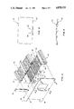
- FIG. 1 is a partially cut away perspective view of an electronic module inserted in a shelf assembly of a portion of the present invention
- FIG. 2 is a perspective exploded view of the shelf assembly
- FIG. 3 is a side view of an electronic module and a portion of the shelf assembly.
- FIG. 4 is a cross sectional view of the shelf assembly.
- the present invention has general applicability but is most advantageously utilized for a shelf assembly which is used for supporting electronic modules, printed circuit boards or the like.
- Electronic shelf assemblies for supporting printed circuit boards are well known in the prior art.
- the printed circuit boards or electronic modules are plugged into connector plugs on a back plane assembly within the electronic shelf assembly.
- the present invention ovecomes this problem in the prior art.
- an electronic module 10 has a back edge 12 carrying a plurality of electrical contacts 14 which make electrical connection with internal contacts of the connector plug 16.
- a lower support 18 carries ribs 20 which form a guide channel as will be explained below.
- a corresponding upper support which has a guide channel for a top edge 24 of the module 10.
- a bottom edge 22 of the module 10 is contained in the lower guide channel formed by the ribs 20.
- a small raised extension 26 on the lower support 18 engages a recess 28 in the module 10.
- the extension 26 is located approximately in the center of the lower support 18, although the present invention would work equally well even if the small extension 26 was offset from the center location as shown in FIG. 1.
- the lower support 18 has enough flexibility that as the module 10 is slid into the shelf assembly along the guide channel, the extension 26 will flex downward until the module 10 is fully inserted, at which time, the extension 26 will return to its normal position and be within the recess 28 of the module 10.
- the module 10 is restrained from disengaging from the connector 16 due to vibrations. Only a significant force by an operator will be able to disengage the module 10 at its recess 28 from the extension 26.
- a first substantially flat, flexible, preformed plastic plate 30 has a plurality of parallel guide channels 32 defined by opposed parallel ribs 34.
- the plate 30 has a predetermined, convex contour perpendicular to the guide channels 32, as shown in FIG. 4.
- Small raised extensions 34 in substantially the center of each of the guide channels 32 of the plate 30 project out of the plane of the plate 30 for engaging the recess 28 in at least the first edge 22 of the module 10 when the module 10 is fully inserted in one of the guide channels 32.
- a second substantially flat, flexible, preformed plastic plate 36 has a plurality of parallel guide channels 38 defined by opposed parallel ribs 40 projecting out of the plane of the second plate 36.
- the guide channels 38 of the second plate 36 are longitudinally aligned with perspective ones of the guide channels 32 of the first plate 30.
- Rigid means 42 extends between the first and second plates 30 and 36 for interconnecting the first and second plates 30 and 36.
- the second plate 36 can also be constructed similar to the first plate 30 and have a predetermined convex contour perpendicular to the guide channels 38.
- the second plate 36 may then have its own small raised extensions projecting out of the plane of the second plate 36 and located substantially in the center of each of the guide channels. These small extensions would then engage a corresponding recess in a second or top edge of the module 10 when the module 10 is fully inserted in one of the guide channels 32, 38.
- the shelf assembly may have at least first and second cross members 44 and 46 attached to a front end 48 and a back end 50, respectively, of each of the first and second plates 30 and 36.
- Each of the cross members 44 and 46 are also attached to the rigid means 42.
- a third cross member 52 may be attached to edge regions 54 of each of the first and second plates 30 and 36 and located substantially in the middle of the first and second plates 30 and 36. This third cross member 52 is opposed from the small raised extensions 34.
- the third cross member 52 is also attached to the rigid means 42.
- the specific shape of the extensions 34 and the recess 28 may have a variety of configurations.
- the leading and trailing edges of the extension 34 may be sloped to allow for ease of insertion and removal of the module 10 from the guide channels.
Landscapes
- Engineering & Computer Science (AREA)
- Microelectronics & Electronic Packaging (AREA)
- Mounting Of Printed Circuit Boards And The Like (AREA)
Abstract
Description
Claims (4)
Priority Applications (1)
| Application Number | Priority Date | Filing Date | Title |
|---|---|---|---|
| US07/197,373 US4878153A (en) | 1988-05-23 | 1988-05-23 | Electronic shelf assembly |
Applications Claiming Priority (1)
| Application Number | Priority Date | Filing Date | Title |
|---|---|---|---|
| US07/197,373 US4878153A (en) | 1988-05-23 | 1988-05-23 | Electronic shelf assembly |
Publications (1)
| Publication Number | Publication Date |
|---|---|
| US4878153A true US4878153A (en) | 1989-10-31 |
Family
ID=22729136
Family Applications (1)
| Application Number | Title | Priority Date | Filing Date |
|---|---|---|---|
| US07/197,373 Expired - Fee Related US4878153A (en) | 1988-05-23 | 1988-05-23 | Electronic shelf assembly |
Country Status (1)
| Country | Link |
|---|---|
| US (1) | US4878153A (en) |
Cited By (7)
| Publication number | Priority date | Publication date | Assignee | Title |
|---|---|---|---|---|
| US5313369A (en) * | 1992-11-03 | 1994-05-17 | Digital Equipment Corporation | Reduced tolerance interconnect system |
| US6158699A (en) * | 1997-09-10 | 2000-12-12 | Micron Electronics, Inc. | Apparatus for mounting computer components |
| US6176001B1 (en) | 1997-09-10 | 2001-01-23 | Micron Electronics, Inc. | Method for mounting computer components |
| US6276041B1 (en) * | 1997-09-10 | 2001-08-21 | Micron Technology, Inc. | Method for coupling computer components |
| US6330991B1 (en) | 1997-06-23 | 2001-12-18 | Micron Technology, Inc. | Apparatus for mounting an element |
| US6377447B1 (en) | 1999-09-16 | 2002-04-23 | Micron Technology, Inc. | Quick release disk drive to chassis mounting apparatus and method |
| US6522556B2 (en) | 1997-09-10 | 2003-02-18 | Micron Technology, Inc. | Apparatus for coupling computer components |
Citations (6)
| Publication number | Priority date | Publication date | Assignee | Title |
|---|---|---|---|---|
| US3574204A (en) * | 1969-07-03 | 1971-04-06 | Yoshitomi Pharmaceutical | Piperidine spiro compounds |
| US3899721A (en) * | 1974-03-20 | 1975-08-12 | Bell Telephone Labor Inc | Printed circuit card guide |
| US3932016A (en) * | 1973-04-02 | 1976-01-13 | Stromberg-Carlson Corporation | Printed circuit card receptacle |
| US4520428A (en) * | 1983-02-02 | 1985-05-28 | The United State Of America As Represented By The Secretary Of The Navy | Dense packaging system for printer wiring boards |
| US4664265A (en) * | 1986-06-09 | 1987-05-12 | Liberty Diversified Industries | Circuit board carrier |
| US4688149A (en) * | 1982-04-15 | 1987-08-18 | Tokai Electric Wire Company, Ltd. | Electrical junction box |
-
1988
- 1988-05-23 US US07/197,373 patent/US4878153A/en not_active Expired - Fee Related
Patent Citations (6)
| Publication number | Priority date | Publication date | Assignee | Title |
|---|---|---|---|---|
| US3574204A (en) * | 1969-07-03 | 1971-04-06 | Yoshitomi Pharmaceutical | Piperidine spiro compounds |
| US3932016A (en) * | 1973-04-02 | 1976-01-13 | Stromberg-Carlson Corporation | Printed circuit card receptacle |
| US3899721A (en) * | 1974-03-20 | 1975-08-12 | Bell Telephone Labor Inc | Printed circuit card guide |
| US4688149A (en) * | 1982-04-15 | 1987-08-18 | Tokai Electric Wire Company, Ltd. | Electrical junction box |
| US4520428A (en) * | 1983-02-02 | 1985-05-28 | The United State Of America As Represented By The Secretary Of The Navy | Dense packaging system for printer wiring boards |
| US4664265A (en) * | 1986-06-09 | 1987-05-12 | Liberty Diversified Industries | Circuit board carrier |
Non-Patent Citations (2)
| Title |
|---|
| D. E. Rutter, Sr., AIR BAG, IBM Tech. Disc. Bull., vol. 11, #12, May 1969, p. 1694. |
| D. E. Rutter, Sr., AIR BAG, IBM Tech. Disc. Bull., vol. 11, 12, May 1969, p. 1694. * |
Cited By (7)
| Publication number | Priority date | Publication date | Assignee | Title |
|---|---|---|---|---|
| US5313369A (en) * | 1992-11-03 | 1994-05-17 | Digital Equipment Corporation | Reduced tolerance interconnect system |
| US6330991B1 (en) | 1997-06-23 | 2001-12-18 | Micron Technology, Inc. | Apparatus for mounting an element |
| US6158699A (en) * | 1997-09-10 | 2000-12-12 | Micron Electronics, Inc. | Apparatus for mounting computer components |
| US6176001B1 (en) | 1997-09-10 | 2001-01-23 | Micron Electronics, Inc. | Method for mounting computer components |
| US6276041B1 (en) * | 1997-09-10 | 2001-08-21 | Micron Technology, Inc. | Method for coupling computer components |
| US6522556B2 (en) | 1997-09-10 | 2003-02-18 | Micron Technology, Inc. | Apparatus for coupling computer components |
| US6377447B1 (en) | 1999-09-16 | 2002-04-23 | Micron Technology, Inc. | Quick release disk drive to chassis mounting apparatus and method |
Similar Documents
| Publication | Publication Date | Title |
|---|---|---|
| US5689405A (en) | IC card rear board support | |
| US5184961A (en) | Modular connector frame | |
| US3008113A (en) | Electrical interconnecting and mounting device for printed-circuit boards | |
| US6540522B2 (en) | Electrical connector assembly for orthogonally mating circuit boards | |
| US3795888A (en) | Printed circuit board edge connector requiring zero insertion force | |
| US7435095B1 (en) | Electrical interconnection system | |
| EP0746063B1 (en) | Connector for a circuit board | |
| EP0670616A1 (en) | Connector for a cable for high frequency signals | |
| US5469332A (en) | PC card assembly | |
| US5205753A (en) | Circuit board structure | |
| EP0511655B1 (en) | Electrical connector to be mounted on a circuit board | |
| GB2260658A (en) | Electrical connector with module holder | |
| JP2006004949A (en) | Connector | |
| US3810433A (en) | Printed circuit card guide | |
| US4878153A (en) | Electronic shelf assembly | |
| US6179650B1 (en) | Modularized electric connector | |
| US4361861A (en) | Apparatus housing comprising a number of parallel component boards | |
| US4795362A (en) | Circuit connector for use with printed wiring board | |
| JP4700674B2 (en) | Locking device to prevent insertion error in printed circuit board connector | |
| EP1471606B1 (en) | Electrical connector assembly | |
| KR19990007851A (en) | Electrical connectors and connector assemblies | |
| US5458498A (en) | Electrical connector for connecting flexible printed circuit board | |
| US6667887B2 (en) | Method and apparatus for locating and securing a component in a computer system | |
| US4900274A (en) | Keying system for assuring proper array configuration of cable cards | |
| US20030128935A1 (en) | Optical connector |
Legal Events
| Date | Code | Title | Description |
|---|---|---|---|
| AS | Assignment |
Owner name: ROCKWELL INTERNATIONAL CORP., Free format text: ASSIGNMENT OF ASSIGNORS INTEREST.;ASSIGNOR:LORIS, WILLIAM P.;REEL/FRAME:004895/0405 Effective date: 19880519 |
|
| AS | Assignment |
Owner name: CHARLES INDUSTRIES, LTD., A CORP. OF IL, ILLINOIS Free format text: ASSIGNMENT OF ASSIGNORS INTEREST.;ASSIGNOR:ROCKWELL INTERNATIONAL CORPORATION, A DE CORP.;REEL/FRAME:005594/0701 Effective date: 19910201 |
|
| AS | Assignment |
Owner name: LASALLE NATIONAL BANK, ILLINOIS Free format text: SECURITY INTEREST;ASSIGNOR:CHARLES INDUSTRIES, LTD.;REEL/FRAME:006611/0216 Effective date: 19920908 |
|
| REMI | Maintenance fee reminder mailed | ||
| LAPS | Lapse for failure to pay maintenance fees | ||
| FP | Lapsed due to failure to pay maintenance fee |
Effective date: 19931031 |
|
| AS | Assignment |
Owner name: CHARLES INDUSTRIES, LTD., ILLINOIS Free format text: RELEASE OF SECURITY INTEREST;ASSIGNOR:LASALLE NATIONAL BANK;REEL/FRAME:007467/0624 Effective date: 19950509 |
|
| STCH | Information on status: patent discontinuation |
Free format text: PATENT EXPIRED DUE TO NONPAYMENT OF MAINTENANCE FEES UNDER 37 CFR 1.362 |