US4880191A - Mounting arrangement for display terminal - Google Patents
Mounting arrangement for display terminal Download PDFInfo
- Publication number
- US4880191A US4880191A US06/814,536 US81453685A US4880191A US 4880191 A US4880191 A US 4880191A US 81453685 A US81453685 A US 81453685A US 4880191 A US4880191 A US 4880191A
- Authority
- US
- United States
- Prior art keywords
- display terminal
- recess
- flexible tabs
- swivel
- cabinet
- Prior art date
- Legal status (The legal status is an assumption and is not a legal conclusion. Google has not performed a legal analysis and makes no representation as to the accuracy of the status listed.)
- Expired - Fee Related
Links
Images

Classifications
-
- F—MECHANICAL ENGINEERING; LIGHTING; HEATING; WEAPONS; BLASTING
- F16—ENGINEERING ELEMENTS AND UNITS; GENERAL MEASURES FOR PRODUCING AND MAINTAINING EFFECTIVE FUNCTIONING OF MACHINES OR INSTALLATIONS; THERMAL INSULATION IN GENERAL
- F16M—FRAMES, CASINGS OR BEDS OF ENGINES, MACHINES OR APPARATUS, NOT SPECIFIC TO ENGINES, MACHINES OR APPARATUS PROVIDED FOR ELSEWHERE; STANDS; SUPPORTS
- F16M11/00—Stands or trestles as supports for apparatus or articles placed thereon Stands for scientific apparatus such as gravitational force meters
- F16M11/02—Heads
- F16M11/04—Means for attachment of apparatus; Means allowing adjustment of the apparatus relatively to the stand
- F16M11/06—Means for attachment of apparatus; Means allowing adjustment of the apparatus relatively to the stand allowing pivoting
- F16M11/12—Means for attachment of apparatus; Means allowing adjustment of the apparatus relatively to the stand allowing pivoting in more than one direction
- F16M11/126—Means for attachment of apparatus; Means allowing adjustment of the apparatus relatively to the stand allowing pivoting in more than one direction for tilting and panning
-
- F—MECHANICAL ENGINEERING; LIGHTING; HEATING; WEAPONS; BLASTING
- F16—ENGINEERING ELEMENTS AND UNITS; GENERAL MEASURES FOR PRODUCING AND MAINTAINING EFFECTIVE FUNCTIONING OF MACHINES OR INSTALLATIONS; THERMAL INSULATION IN GENERAL
- F16M—FRAMES, CASINGS OR BEDS OF ENGINES, MACHINES OR APPARATUS, NOT SPECIFIC TO ENGINES, MACHINES OR APPARATUS PROVIDED FOR ELSEWHERE; STANDS; SUPPORTS
- F16M2200/00—Details of stands or supports
- F16M2200/08—Foot or support base
-
- Y—GENERAL TAGGING OF NEW TECHNOLOGICAL DEVELOPMENTS; GENERAL TAGGING OF CROSS-SECTIONAL TECHNOLOGIES SPANNING OVER SEVERAL SECTIONS OF THE IPC; TECHNICAL SUBJECTS COVERED BY FORMER USPC CROSS-REFERENCE ART COLLECTIONS [XRACs] AND DIGESTS
- Y10—TECHNICAL SUBJECTS COVERED BY FORMER USPC
- Y10S—TECHNICAL SUBJECTS COVERED BY FORMER USPC CROSS-REFERENCE ART COLLECTIONS [XRACs] AND DIGESTS
- Y10S248/00—Supports
- Y10S248/917—Video display screen support
- Y10S248/919—Adjustably orientable video screen support
- Y10S248/922—Angular
- Y10S248/923—Tilting
Definitions
- Data display terminals include a cabinet which contains a cathode ray tube (CRT) and various circuit modules which process electrical signals for display on the CRT.
- CRT cathode ray tube
- one form of cabinet includes in its bottom surface a spherical section which is seated on a support base having a concave depression in which the spherical section is seated for supporting the terminal.
- This arrangement permits the terminal cabinet to be tilted and swiveled by the user.
- the support base is an expensive extra part, and the cabinet having the integral spherical projection must always be used with the extra base. If the user wanted to set the cabinet directly on a desk or table, he could not.
- the present invention provides a terminal cabinet having an optional removable spherical support.
- FIG. 1 is a perspective exploded view of the invention.
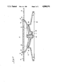
- FIG. 2 is a sectional view of a portion of the invention.
- a data display terminal 10 embodying the invention includes a cabinet 20 containing a cathode ray tube, hardware, and various circuit boards (not shown).
- the base 30 of the cabinet is provided with a circular array of apertures 40, each of which is shown as being rectangular, but other shapes can be used.
- an optional tilt-swivel assembly 44 is provided which includes a truncated ball or spherical section 50 having a circumference along which are provided a plurality of slightly flexible tabs 60, preferably identical in number to the number of apertures 40 in the base 30 of the cabinet 20, so that the truncated ball can be snapped into tight engagement with the base of the cabinet by inserting the tabs 60 into the apertures 40.
- Each tab 60 includes at its upper end a lip 62 which can engage the edge of the cabinet base which defines an aperture 40, as seen in FIG. 2.
- a disk 70 is seated on the top surface of the ball 50, and the disk has a projecting key 80 which projects downwardly from its lower surface and is seated in a slot 90 in the ball.
- the disk 70 is thus arranged to move back and forth only along the slot 90.
- the ball 50 is seated on an O-ring 100 which is seated in a concave depression 110 in a pedestal 120.
- the key 80 of disk 70 enters the keyway 130 in the depression 110 in the pedestal 120, and a screw 140 is secured to the disk 70 to secure all of the parts together.
- the tilt-swivel assembly 44 is not secured to the cabinet.
- the assembly 44 is coupled to the cabinet by inserting the tabs 60 on the ball 50 into the holes 40 in the base of the cabinet where they are locked in place.
- the cabinet swivels due to the ball 50 riding on O-rings 100, and it tilts by means of key 80 guided in slot 90 in ball 50; that is, the ball 50 moves with respect to the key.
Abstract
Description
Claims (12)
Priority Applications (1)
| Application Number | Priority Date | Filing Date | Title |
|---|---|---|---|
| US06/814,536 US4880191A (en) | 1984-07-05 | 1985-12-20 | Mounting arrangement for display terminal |
Applications Claiming Priority (2)
| Application Number | Priority Date | Filing Date | Title |
|---|---|---|---|
| US62785584A | 1984-07-05 | 1984-07-05 | |
| US06/814,536 US4880191A (en) | 1984-07-05 | 1985-12-20 | Mounting arrangement for display terminal |
Related Parent Applications (1)
| Application Number | Title | Priority Date | Filing Date |
|---|---|---|---|
| US62785584A Continuation | 1984-07-05 | 1984-07-05 |
Publications (1)
| Publication Number | Publication Date |
|---|---|
| US4880191A true US4880191A (en) | 1989-11-14 |
Family
ID=27090547
Family Applications (1)
| Application Number | Title | Priority Date | Filing Date |
|---|---|---|---|
| US06/814,536 Expired - Fee Related US4880191A (en) | 1984-07-05 | 1985-12-20 | Mounting arrangement for display terminal |
Country Status (1)
| Country | Link |
|---|---|
| US (1) | US4880191A (en) |
Cited By (54)
| Publication number | Priority date | Publication date | Assignee | Title |
|---|---|---|---|---|
| US4989813A (en) * | 1989-11-29 | 1991-02-05 | Samsung Electron Devices Co., Ltd. | Supporting base for controlling height, swivel and inclination of display means |
| US5145134A (en) * | 1990-06-14 | 1992-09-08 | Matsushita Electric Industrial Co., Ltd. | Tiltable-turntable for display monitor |
| US5157585A (en) * | 1991-06-27 | 1992-10-20 | Compaq Computer Corporation | Compact AC-powerable portable computer having a CPU and expansion bay in an upper housing pivotally attached to a lower housing |
| US5209446A (en) * | 1991-02-18 | 1993-05-11 | Mitsubishi Denki Kabushiki Kaisha | Rotary stand |
| FR2688864A1 (en) * | 1992-03-19 | 1993-09-24 | Bes Claude | Device used to provide rotational support and guidance for various objects |
| US5398903A (en) * | 1992-07-07 | 1995-03-21 | Samsung Display Devices Co., Ltd. | Video display mounting device |
| US5404182A (en) * | 1993-10-28 | 1995-04-04 | Nippon Control Industrial Co., Ltd. | Swivel chassis |
| DE4400305A1 (en) * | 1994-01-07 | 1995-07-13 | Hartmut S Engel | Integratable TV set support |
| US5465936A (en) * | 1994-08-16 | 1995-11-14 | Wang; Tsong L. | Rotatable bracket of a monitor |
| US5518216A (en) * | 1993-11-05 | 1996-05-21 | Acer Peripherals, Inc. | Direction and an angle adjustment apparatus for a video display device |
| US5569895A (en) * | 1993-05-27 | 1996-10-29 | International Business Machines Corporation | I/O assembly for use with point of sale terminals and other computing systems |
| US5587876A (en) * | 1995-03-30 | 1996-12-24 | Apple Computer, Inc. | Modular monitor architecture |
| US5603478A (en) * | 1995-08-14 | 1997-02-18 | Wang; Daniel | Keyboard support |
| US5683068A (en) * | 1995-04-03 | 1997-11-04 | Apple Computer, Inc. | Tilt/swivel support for personal computer monitor |
| US5941618A (en) * | 1997-03-11 | 1999-08-24 | Mustek Corporation | Integrated point-of-sale cabinet system with removable covers |
| US5941493A (en) * | 1996-11-16 | 1999-08-24 | Adi Corporation | LCD support system |
| NL1012402C2 (en) * | 1999-06-22 | 2000-12-28 | Vogel S Holding Bv | Locking arrangement for securing a television set to its mounting base |
| US6446913B1 (en) * | 1998-07-23 | 2002-09-10 | Robert Bosch Gmbh | Device for fixing and aligning an apparatus in a holder frame |
| US6644616B1 (en) * | 1999-12-14 | 2003-11-11 | Fujitsu Limited | Tilt swivel stand |
| US20030230693A1 (en) * | 2002-06-18 | 2003-12-18 | Ching-Hui Yen | Detachable base support |
| US6712326B2 (en) * | 2001-08-31 | 2004-03-30 | Matsushita Electric Industrial Co., Ltd. | Rotary stand for an electric appliance |
| US6801426B2 (en) * | 2001-04-16 | 2004-10-05 | Fujitsu Limited | Display device with pivotable base |
| US20060022102A1 (en) * | 2003-05-30 | 2006-02-02 | Jay Dittmer | Self-balancing adjustable mounting system with friction adjustment |
| WO2006033494A1 (en) * | 2004-09-23 | 2006-03-30 | Se A Mechanics Co., Ltd. | An angle regulating apparatus of a display device |
| US20060065800A1 (en) * | 2004-09-29 | 2006-03-30 | Jeff Bremmon | Universal mount for flat panel displays |
| US7028961B1 (en) * | 2003-05-30 | 2006-04-18 | Csav, Inc. | Self-balancing adjustable flat panel mounting system |
| US20060231699A1 (en) * | 2005-02-24 | 2006-10-19 | Compal Electronics, Inc. | Supporting structure for display panel |
| US20060289716A1 (en) * | 2005-06-24 | 2006-12-28 | Innolux Display Corp. | Flat panel display with detachable base |
| US20070047188A1 (en) * | 2005-08-23 | 2007-03-01 | Samsung Electronics Co., Ltd. | Display apparatus |
| WO2007046563A1 (en) * | 2005-10-19 | 2007-04-26 | Se A Mechanics Co., Ltd. | Angle regulating apparatus of display device |
| US20070153459A1 (en) * | 2006-01-04 | 2007-07-05 | Jim Wohlford | Mounting system for flat panel electronic display |
| US7361046B2 (en) * | 2005-07-01 | 2008-04-22 | Hewlett-Packard Development Company, L.P. | Display assembly |
| US20080099420A1 (en) * | 2006-11-01 | 2008-05-01 | Inventec Multimedia & Telecom Corporation | Rotatable Stand with Adjustable Tightness |
| US7395996B2 (en) | 2002-06-11 | 2008-07-08 | Csav, Inc. | Adjustable, self-balancing flat panel display mounting system |
| KR100861690B1 (en) | 2008-05-22 | 2008-10-06 | 태우 주식회사 | A panel display wall-mount |
| US20090045313A1 (en) * | 2007-08-15 | 2009-02-19 | Chih-Hsien Huang | Mechanism utilized to adjust inclination angle and horizontal rotation angle |
| USD620943S1 (en) | 2009-01-07 | 2010-08-03 | Milestone Av Technologies Llc | Single arm display mount |
| US20100271798A1 (en) * | 2007-12-28 | 2010-10-28 | Jindong Yeo | Wall mounting apparatus |
| USD627787S1 (en) | 2009-01-07 | 2010-11-23 | Milestone Av Technologies Llc | Display mount with single articulating arm |
| US7866622B2 (en) | 2007-01-05 | 2011-01-11 | Milestone Av Technologies Llc | In-wall mount |
| JP2011156996A (en) * | 2010-02-02 | 2011-08-18 | Yupiteru Corp | Support structure for fixing electronic device in cabin and electronic device using the same |
| US20110245641A1 (en) * | 2010-03-31 | 2011-10-06 | Nellcor Puritan Bennett Llc | Monitor With Multi-Position Base |
| US8072739B2 (en) | 2007-01-03 | 2011-12-06 | Milestone Av Technologies Llc | Device mount with selectively positionable tilt axis |
| US8094438B2 (en) | 2007-01-05 | 2012-01-10 | Milestone Av Technologies Llc | Wall-avoiding self-balancing mount for tilt positioning of a flat panel electronic display |
| US20120153789A1 (en) * | 2010-12-21 | 2012-06-21 | Alpha Networks Inc. | Pivoting assembly with positioning function |
| US8235342B2 (en) | 2003-01-09 | 2012-08-07 | Milestone AV Techonologies LLC | Adjustable tilt mount |
| US20130037671A1 (en) * | 2011-08-10 | 2013-02-14 | Syncmold Enterprise Corp. | Monitor mounting apparatus |
| US20140183314A1 (en) * | 2012-04-16 | 2014-07-03 | Iordanka Koleva Mulhern | Cradle Apparatus and Method for Rotating and Linearly Displacing an Electronic Device |
| US8891249B2 (en) | 2009-01-07 | 2014-11-18 | Milestone Av Technologies Llc | Display mount with adjustable position tilt axis |
| US20140339385A1 (en) * | 2013-05-14 | 2014-11-20 | Rosemount Aerospace Inc. | Rotating electronic display mount |
| US20150050071A1 (en) * | 2012-04-09 | 2015-02-19 | Illinois Tool Works Inc. | Arcuate clip assembly |
| US9109742B2 (en) | 2008-09-02 | 2015-08-18 | Milestone Av Technologies Llc | Low profile mount for flat panel electronic display |
| US10344911B2 (en) | 2016-09-20 | 2019-07-09 | Colebrook Bosson Saunders (Products) Limited | Tilt mechanism |
| USD881167S1 (en) * | 2019-12-16 | 2020-04-14 | Shenzhen Healthwell Technology Co., Ltd. | Stand for loudspeaker |
Citations (5)
| Publication number | Priority date | Publication date | Assignee | Title |
|---|---|---|---|---|
| US2520725A (en) * | 1946-08-26 | 1950-08-29 | Tinnerman Products Inc | Support construction and fastening device therefor |
| US3699580A (en) * | 1971-01-18 | 1972-10-17 | Gen Electric | Antenna mounting clip |
| US3908942A (en) * | 1974-04-25 | 1975-09-30 | Morton Metalcraft Co | Mounting means for television sets and the like |
| US4068961A (en) * | 1976-08-23 | 1978-01-17 | Milgo Electronic Corporation | Swivel joint |
| US4415136A (en) * | 1981-05-12 | 1983-11-15 | Dentronix Systems, Inc. | Pedestal for consoles |
-
1985
- 1985-12-20 US US06/814,536 patent/US4880191A/en not_active Expired - Fee Related
Patent Citations (5)
| Publication number | Priority date | Publication date | Assignee | Title |
|---|---|---|---|---|
| US2520725A (en) * | 1946-08-26 | 1950-08-29 | Tinnerman Products Inc | Support construction and fastening device therefor |
| US3699580A (en) * | 1971-01-18 | 1972-10-17 | Gen Electric | Antenna mounting clip |
| US3908942A (en) * | 1974-04-25 | 1975-09-30 | Morton Metalcraft Co | Mounting means for television sets and the like |
| US4068961A (en) * | 1976-08-23 | 1978-01-17 | Milgo Electronic Corporation | Swivel joint |
| US4415136A (en) * | 1981-05-12 | 1983-11-15 | Dentronix Systems, Inc. | Pedestal for consoles |
Cited By (78)
| Publication number | Priority date | Publication date | Assignee | Title |
|---|---|---|---|---|
| US4989813A (en) * | 1989-11-29 | 1991-02-05 | Samsung Electron Devices Co., Ltd. | Supporting base for controlling height, swivel and inclination of display means |
| US5145134A (en) * | 1990-06-14 | 1992-09-08 | Matsushita Electric Industrial Co., Ltd. | Tiltable-turntable for display monitor |
| US5209446A (en) * | 1991-02-18 | 1993-05-11 | Mitsubishi Denki Kabushiki Kaisha | Rotary stand |
| US5157585A (en) * | 1991-06-27 | 1992-10-20 | Compaq Computer Corporation | Compact AC-powerable portable computer having a CPU and expansion bay in an upper housing pivotally attached to a lower housing |
| FR2688864A1 (en) * | 1992-03-19 | 1993-09-24 | Bes Claude | Device used to provide rotational support and guidance for various objects |
| US5398903A (en) * | 1992-07-07 | 1995-03-21 | Samsung Display Devices Co., Ltd. | Video display mounting device |
| US5971268A (en) * | 1993-05-27 | 1999-10-26 | International Business Machines Corporation | I/O assembly for use with point of sale terminals and other computing systems |
| US5569895A (en) * | 1993-05-27 | 1996-10-29 | International Business Machines Corporation | I/O assembly for use with point of sale terminals and other computing systems |
| US5404182A (en) * | 1993-10-28 | 1995-04-04 | Nippon Control Industrial Co., Ltd. | Swivel chassis |
| US5518216A (en) * | 1993-11-05 | 1996-05-21 | Acer Peripherals, Inc. | Direction and an angle adjustment apparatus for a video display device |
| DE4400305A1 (en) * | 1994-01-07 | 1995-07-13 | Hartmut S Engel | Integratable TV set support |
| US5465936A (en) * | 1994-08-16 | 1995-11-14 | Wang; Tsong L. | Rotatable bracket of a monitor |
| US5587876A (en) * | 1995-03-30 | 1996-12-24 | Apple Computer, Inc. | Modular monitor architecture |
| US5683068A (en) * | 1995-04-03 | 1997-11-04 | Apple Computer, Inc. | Tilt/swivel support for personal computer monitor |
| US5603478A (en) * | 1995-08-14 | 1997-02-18 | Wang; Daniel | Keyboard support |
| US5941493A (en) * | 1996-11-16 | 1999-08-24 | Adi Corporation | LCD support system |
| US5941618A (en) * | 1997-03-11 | 1999-08-24 | Mustek Corporation | Integrated point-of-sale cabinet system with removable covers |
| US6446913B1 (en) * | 1998-07-23 | 2002-09-10 | Robert Bosch Gmbh | Device for fixing and aligning an apparatus in a holder frame |
| NL1012402C2 (en) * | 1999-06-22 | 2000-12-28 | Vogel S Holding Bv | Locking arrangement for securing a television set to its mounting base |
| US6644616B1 (en) * | 1999-12-14 | 2003-11-11 | Fujitsu Limited | Tilt swivel stand |
| US20040051012A1 (en) * | 1999-12-14 | 2004-03-18 | Fujitsu Limited | Tilt-swivel stand |
| US6869056B2 (en) | 1999-12-14 | 2005-03-22 | Fujitsu Limited | Tilt-swivel stand |
| US6801426B2 (en) * | 2001-04-16 | 2004-10-05 | Fujitsu Limited | Display device with pivotable base |
| US6712326B2 (en) * | 2001-08-31 | 2004-03-30 | Matsushita Electric Industrial Co., Ltd. | Rotary stand for an electric appliance |
| US7395996B2 (en) | 2002-06-11 | 2008-07-08 | Csav, Inc. | Adjustable, self-balancing flat panel display mounting system |
| US8490934B2 (en) | 2002-06-11 | 2013-07-23 | Milestone Av Technologies Llc | Adjustable, self-balancing flat panel display mounting system |
| US7954780B2 (en) | 2002-06-11 | 2011-06-07 | Milestone Av Technologies Llc | Adjustable self-balancing flat panel display mounting system |
| US20030230693A1 (en) * | 2002-06-18 | 2003-12-18 | Ching-Hui Yen | Detachable base support |
| US7175144B2 (en) * | 2002-06-18 | 2007-02-13 | Benq Corporation | Detachable base support |
| US8235342B2 (en) | 2003-01-09 | 2012-08-07 | Milestone AV Techonologies LLC | Adjustable tilt mount |
| US7028961B1 (en) * | 2003-05-30 | 2006-04-18 | Csav, Inc. | Self-balancing adjustable flat panel mounting system |
| US20060186295A1 (en) * | 2003-05-30 | 2006-08-24 | Chief Manufacturing Inc. | Self-balancing adjustable flat panel mounting system |
| US20080117580A1 (en) * | 2003-05-30 | 2008-05-22 | Jay Dittmer | Self-balancing adjustable flat panel mounting system |
| US7823849B2 (en) | 2003-05-30 | 2010-11-02 | Milestone Av Technologies Llc | Self-balancing adjustable flat panel mounting system |
| US20100214729A1 (en) * | 2003-05-30 | 2010-08-26 | Jay Dittmer | Self-balancing adjustable flat panel mounting system |
| US9279536B2 (en) | 2003-05-30 | 2016-03-08 | Milestone Av Technologies Llc | Self-balancing adjustable flat panel mounting system |
| US7387286B2 (en) | 2003-05-30 | 2008-06-17 | Csav, Inc. | Self-balancing adjustable flat panel mounting system |
| US7380760B2 (en) | 2003-05-30 | 2008-06-03 | Csav, Inc. | Self-balancing adjustable mounting system with friction adjustment |
| US20060022102A1 (en) * | 2003-05-30 | 2006-02-02 | Jay Dittmer | Self-balancing adjustable mounting system with friction adjustment |
| JP2008513846A (en) * | 2004-09-23 | 2008-05-01 | セ ア メカニクス カンパニー リミテッド | Angle adjustment device for display equipment |
| US20090201661A1 (en) * | 2004-09-23 | 2009-08-13 | Kim Kyung Wook | Angle regulating apparatus of a display device |
| WO2006033494A1 (en) * | 2004-09-23 | 2006-03-30 | Se A Mechanics Co., Ltd. | An angle regulating apparatus of a display device |
| US20060065800A1 (en) * | 2004-09-29 | 2006-03-30 | Jeff Bremmon | Universal mount for flat panel displays |
| US20060231699A1 (en) * | 2005-02-24 | 2006-10-19 | Compal Electronics, Inc. | Supporting structure for display panel |
| US7607621B2 (en) * | 2005-06-24 | 2009-10-27 | Innocom Technology (Shenzhen) Co., Ltd. | Flat panel display with detachable base |
| US20060289716A1 (en) * | 2005-06-24 | 2006-12-28 | Innolux Display Corp. | Flat panel display with detachable base |
| US7361046B2 (en) * | 2005-07-01 | 2008-04-22 | Hewlett-Packard Development Company, L.P. | Display assembly |
| US8000092B2 (en) * | 2005-08-23 | 2011-08-16 | Samsung Electronics Co., Ltd. | Display apparatus |
| US20070047188A1 (en) * | 2005-08-23 | 2007-03-01 | Samsung Electronics Co., Ltd. | Display apparatus |
| WO2007046563A1 (en) * | 2005-10-19 | 2007-04-26 | Se A Mechanics Co., Ltd. | Angle regulating apparatus of display device |
| US20070153459A1 (en) * | 2006-01-04 | 2007-07-05 | Jim Wohlford | Mounting system for flat panel electronic display |
| US20080099420A1 (en) * | 2006-11-01 | 2008-05-01 | Inventec Multimedia & Telecom Corporation | Rotatable Stand with Adjustable Tightness |
| US8072739B2 (en) | 2007-01-03 | 2011-12-06 | Milestone Av Technologies Llc | Device mount with selectively positionable tilt axis |
| US7866622B2 (en) | 2007-01-05 | 2011-01-11 | Milestone Av Technologies Llc | In-wall mount |
| US8508918B2 (en) | 2007-01-05 | 2013-08-13 | Milestone Av Technologies Llc | Wall-avoiding self-balancing mount for tilt positioning of a flat panel electronic display |
| US8094438B2 (en) | 2007-01-05 | 2012-01-10 | Milestone Av Technologies Llc | Wall-avoiding self-balancing mount for tilt positioning of a flat panel electronic display |
| US20090045313A1 (en) * | 2007-08-15 | 2009-02-19 | Chih-Hsien Huang | Mechanism utilized to adjust inclination angle and horizontal rotation angle |
| US20100271798A1 (en) * | 2007-12-28 | 2010-10-28 | Jindong Yeo | Wall mounting apparatus |
| US8480049B2 (en) * | 2007-12-28 | 2013-07-09 | Lg Electronics Inc. | Wall mounting apparatus |
| KR100861690B1 (en) | 2008-05-22 | 2008-10-06 | 태우 주식회사 | A panel display wall-mount |
| US9109742B2 (en) | 2008-09-02 | 2015-08-18 | Milestone Av Technologies Llc | Low profile mount for flat panel electronic display |
| USD627787S1 (en) | 2009-01-07 | 2010-11-23 | Milestone Av Technologies Llc | Display mount with single articulating arm |
| US8891249B2 (en) | 2009-01-07 | 2014-11-18 | Milestone Av Technologies Llc | Display mount with adjustable position tilt axis |
| USD620943S1 (en) | 2009-01-07 | 2010-08-03 | Milestone Av Technologies Llc | Single arm display mount |
| JP2011156996A (en) * | 2010-02-02 | 2011-08-18 | Yupiteru Corp | Support structure for fixing electronic device in cabin and electronic device using the same |
| US20110245641A1 (en) * | 2010-03-31 | 2011-10-06 | Nellcor Puritan Bennett Llc | Monitor With Multi-Position Base |
| US8651437B2 (en) * | 2010-12-21 | 2014-02-18 | Alpha Networks Inc. | Pivoting assembly with positioning function |
| US20120153789A1 (en) * | 2010-12-21 | 2012-06-21 | Alpha Networks Inc. | Pivoting assembly with positioning function |
| US8678333B2 (en) * | 2011-08-10 | 2014-03-25 | Syncmold Enterprise Corp. | Monitor mounting apparatus |
| US20130037671A1 (en) * | 2011-08-10 | 2013-02-14 | Syncmold Enterprise Corp. | Monitor mounting apparatus |
| US20150050071A1 (en) * | 2012-04-09 | 2015-02-19 | Illinois Tool Works Inc. | Arcuate clip assembly |
| US9475525B2 (en) * | 2012-04-09 | 2016-10-25 | Illinois Tool Works Inc. | Arcuate clip assembly |
| US9080716B2 (en) * | 2012-04-16 | 2015-07-14 | World Richman Mfg. Corp. | Cradle apparatus and method for rotating and linearly displacing an electronic device |
| US20140183314A1 (en) * | 2012-04-16 | 2014-07-03 | Iordanka Koleva Mulhern | Cradle Apparatus and Method for Rotating and Linearly Displacing an Electronic Device |
| US20140339385A1 (en) * | 2013-05-14 | 2014-11-20 | Rosemount Aerospace Inc. | Rotating electronic display mount |
| US9027892B2 (en) * | 2013-05-14 | 2015-05-12 | Rosemount Aerospace Inc. | Rotating electronic display mount |
| US10344911B2 (en) | 2016-09-20 | 2019-07-09 | Colebrook Bosson Saunders (Products) Limited | Tilt mechanism |
| USD881167S1 (en) * | 2019-12-16 | 2020-04-14 | Shenzhen Healthwell Technology Co., Ltd. | Stand for loudspeaker |
Similar Documents
| Publication | Publication Date | Title |
|---|---|---|
| US4880191A (en) | Mounting arrangement for display terminal | |
| US4564166A (en) | Rotary tilt base for video terminal | |
| US4589713A (en) | Video display support joint | |
| US20020053629A1 (en) | Support Device of a display | |
| US4780571A (en) | Combined floor pedestal and floor outlet | |
| US5683068A (en) | Tilt/swivel support for personal computer monitor | |
| US6042426A (en) | Multi-user electrical services outlet | |
| US4570892A (en) | Tiltable rotating display monitor mount | |
| EP0087892A1 (en) | Supporting assembly | |
| US4415136A (en) | Pedestal for consoles | |
| US5249103A (en) | Modular transaction terminal having a docking surface with a plurality of parallel grooves | |
| US4542872A (en) | Terminal with tilt-swivel display | |
| CN215636393U (en) | Clamp apparatus | |
| US5330147A (en) | Video monitor clamp | |
| US6049454A (en) | Computer monitor stand and docking method | |
| US4731030A (en) | Tilt and swivel assembly for terminal monitor | |
| EP0267550B1 (en) | Adjustable tilt/swivel/mounting assembly | |
| US20080142659A1 (en) | Display device | |
| IE55159B1 (en) | Mounting pedestals | |
| US6193208B1 (en) | Stabilizing pedestal for computer system tower units | |
| US7616770B2 (en) | Electro-acoustic apparatus | |
| US6481686B1 (en) | Multifunctional turntable for a leveling device | |
| JPH0715107A (en) | Multistage mounting method for printed board | |
| JP3406048B2 (en) | Assembly structure of tables, desks, etc. | |
| US5178352A (en) | Instrument support device |
Legal Events
| Date | Code | Title | Description |
|---|---|---|---|
| AS | Assignment |
Owner name: UNISYS CORPORATION, PENNSYLVANIA Free format text: MERGER;ASSIGNOR:BURROUGHS CORPORATION;REEL/FRAME:005012/0501 Effective date: 19880509 |
|
| FEPP | Fee payment procedure |
Free format text: PAYOR NUMBER ASSIGNED (ORIGINAL EVENT CODE: ASPN); ENTITY STATUS OF PATENT OWNER: LARGE ENTITY |
|
| REFU | Refund |
Free format text: REFUND PROCESSED. MAINTENANCE FEE HAS ALREADY BEEN PAID (ORIGINAL EVENT CODE: R160); ENTITY STATUS OF PATENT OWNER: LARGE ENTITY |
|
| FPAY | Fee payment |
Year of fee payment: 4 |
|
| REMI | Maintenance fee reminder mailed | ||
| LAPS | Lapse for failure to pay maintenance fees | ||
| FP | Lapsed due to failure to pay maintenance fee |
Effective date: 19971119 |
|
| STCH | Information on status: patent discontinuation |
Free format text: PATENT EXPIRED DUE TO NONPAYMENT OF MAINTENANCE FEES UNDER 37 CFR 1.362 |