US4883033A - Ignition timing control system for internal combustion engines - Google Patents
Ignition timing control system for internal combustion engines Download PDFInfo
- Publication number
- US4883033A US4883033A US07/189,824 US18982488A US4883033A US 4883033 A US4883033 A US 4883033A US 18982488 A US18982488 A US 18982488A US 4883033 A US4883033 A US 4883033A
- Authority
- US
- United States
- Prior art keywords
- ignition
- engine speed
- ignition timing
- internal combustion
- engine
- Prior art date
- Legal status (The legal status is an assumption and is not a legal conclusion. Google has not performed a legal analysis and makes no representation as to the accuracy of the status listed.)
- Expired - Lifetime
Links
Images


Classifications
-
- F—MECHANICAL ENGINEERING; LIGHTING; HEATING; WEAPONS; BLASTING
- F02—COMBUSTION ENGINES; HOT-GAS OR COMBUSTION-PRODUCT ENGINE PLANTS
- F02P—IGNITION, OTHER THAN COMPRESSION IGNITION, FOR INTERNAL-COMBUSTION ENGINES; TESTING OF IGNITION TIMING IN COMPRESSION-IGNITION ENGINES
- F02P9/00—Electric spark ignition control, not otherwise provided for
- F02P9/002—Control of spark intensity, intensifying, lengthening, suppression
- F02P9/005—Control of spark intensity, intensifying, lengthening, suppression by weakening or suppression of sparks to limit the engine speed
-
- F—MECHANICAL ENGINEERING; LIGHTING; HEATING; WEAPONS; BLASTING
- F02—COMBUSTION ENGINES; HOT-GAS OR COMBUSTION-PRODUCT ENGINE PLANTS
- F02P—IGNITION, OTHER THAN COMPRESSION IGNITION, FOR INTERNAL-COMBUSTION ENGINES; TESTING OF IGNITION TIMING IN COMPRESSION-IGNITION ENGINES
- F02P5/00—Advancing or retarding ignition; Control therefor
- F02P5/04—Advancing or retarding ignition; Control therefor automatically, as a function of the working conditions of the engine or vehicle or of the atmospheric conditions
- F02P5/145—Advancing or retarding ignition; Control therefor automatically, as a function of the working conditions of the engine or vehicle or of the atmospheric conditions using electrical means
- F02P5/15—Digital data processing
- F02P5/1502—Digital data processing using one central computing unit
- F02P5/1504—Digital data processing using one central computing unit with particular means during a transient phase, e.g. acceleration, deceleration, gear change
-
- F—MECHANICAL ENGINEERING; LIGHTING; HEATING; WEAPONS; BLASTING
- F02—COMBUSTION ENGINES; HOT-GAS OR COMBUSTION-PRODUCT ENGINE PLANTS
- F02B—INTERNAL-COMBUSTION PISTON ENGINES; COMBUSTION ENGINES IN GENERAL
- F02B1/00—Engines characterised by fuel-air mixture compression
- F02B1/02—Engines characterised by fuel-air mixture compression with positive ignition
- F02B1/04—Engines characterised by fuel-air mixture compression with positive ignition with fuel-air mixture admission into cylinder
-
- Y—GENERAL TAGGING OF NEW TECHNOLOGICAL DEVELOPMENTS; GENERAL TAGGING OF CROSS-SECTIONAL TECHNOLOGIES SPANNING OVER SEVERAL SECTIONS OF THE IPC; TECHNICAL SUBJECTS COVERED BY FORMER USPC CROSS-REFERENCE ART COLLECTIONS [XRACs] AND DIGESTS
- Y02—TECHNOLOGIES OR APPLICATIONS FOR MITIGATION OR ADAPTATION AGAINST CLIMATE CHANGE
- Y02T—CLIMATE CHANGE MITIGATION TECHNOLOGIES RELATED TO TRANSPORTATION
- Y02T10/00—Road transport of goods or passengers
- Y02T10/10—Internal combustion engine [ICE] based vehicles
- Y02T10/40—Engine management systems
Definitions
- the present invention relates to an ignition timing control system for internal combustion engines such as gasoline engines, or more in particular to an ignition timing control system for internal combustion engines having a function to prevent over-revolutions of the engines.
- conventional ignition systems or fuel supply systems are equipped with an over-revolutions prevention mechanism (such as disclosed in JP-A-61-164077) for retarding the ignition timing or stopping the ignition.
- Other conventional systems for internal combustion engines using an electronically-controlled fuel injection unit comprise means for stopping fuel injection to prevent over-revolutions.
- the primary object of the present invention is to provide a method and a system for ignition timing control which is capable of preventing over-revolutions of an internal combustion engine with carburetor using electronic distribution, that is distributorless ignition accurately without any backfire.
- a second object of the present invention is to provide a method and a system for controlling the ignition timing of an internal combustion engine, which is capable of controlling the engine speed successfully under variations of environmental conditions, secular variations or physical variations between different engines.
- an ignition timing control system for multi-cylinder internal combustion engines for controlling the ignition timing electronically in accordance with the operating conditions of the engines, comprising means for stopping ignition, means for retarding the ignition timing, and engine speed-responsive control means for energizing the ignition stop means and the ignition angle retarding means alternately each several times when the engine speed is in a predetermined range.
- an ignition timing control system for internal combustion engines for controlling the ignition timing electronically in accordance with the operating conditions, comprising means for detecting the engine speed of an internal combustion engine, ignition lag control means energized only in a region beyond a first set value of the speed of the internal combustion engine detected by the engine speed detection means for controlling by feedback the ignition lag as predetermined in accordance with the prevailing engine speed, the ignition lag being increased with the engine speed in the region and decreased with the decrease in engine speed in the region, and ignition stop means energized when the engine speed is at a second set value higher than the first set value for stopping the ignition.
- the ignition timing is gradually retarded in a first engine speed region, and depending on the change in engine speed after retardation, is further retarded or advanced.
- the ignition timing is controlled by feedback in accordance with the change in engine speed.
- an over-revolutions can be prevented only by retardation, thereby making possible a control with substantially no shock.
- feedback control of ignition timing permits optimum ignition timing in accordance with changes in operating conditions, etc.
- a method of ignition timing control for internal combustion engines comprising the steps of detecting the engine speed of a multi-cylinder internal combustion engine, sequentially stopping the ignition of the cylinders of the multi-cylinder internal combustion engine when the engine speed exceeds a predetermined level, igniting the cylinders by sequential retardation of ignition timing after stopping ignition for all the cylinders, and repeating the ignition stop and retardation alternately as long as the engine speed is higher than a predetermined level.
- a method of ignition timing control for internal combustion engines comprising the steps of detecting the engine speed of an internal combustion engine, controlling the ignition lag by feedback in such a manner that the ignition lag is increased when the engine speed is increased and the ignition lag is reduced when the engine speed is decreased in accordance with the engine speed changes in the case where the engine speed is higher than a predetermined first engine speed level, and stopping the ignition and retarding the ignition timing alternately when the engine speed is higher than a second predetermined engine speed level which is higher than the first engine speed.
- FIG. 1 is a block diagram showing a configuration of an ignition system for internal combustion engines to which the present invention is applicable.
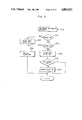
- FIGS. 2 to 4 are flowcharts for explaining an ignition control system according to a first embodiment of the present invention, in which FIG. 2 is a flowchart showing an ignition interruption routine, FIG. 3 a flowchart for deciding on engine speed conditions, and FIG. 4 a flowchart for calculating the ignition timing.
- FIGS. 5 and 6 are timing charts showing the operating conditions of an ignition timing control system according to the first embodiment.
- FIG. 7 is a flowchart similar to FIG. 3 for explaining the operation of an ignition timing control system according to a second embodiment of the present invention.
- FIG. 8 is a timing chart showing the operating conditions of the ignition timing control system according to the second embodiment.
- FIGS. 9 to 11 are flowcharts for explaining the operation of an ignition timing control system according to a third embodiment of the present invention, in which FIG. 9 is a flowchart for ignition interrruption routine, FIG. 10 a flowchart for deciding on the engine speed conditions, and FIG. 11 a flowchart for calculating the ignition timing.
- FIG. 12 is a timing chart showing the operating conditions of an ignition timing control system according to a third embodiment of the present invention.
- FIG. 13 is a timing chart showing the operating conditions of an ignition timing control system according to the third embodiment with the engine under no load.
- FIG. 14 is a flowchart for explaining the operation of an ignition timing control system according to a fourth embodiment of the present invention.
- FIG. 1 shows an embodiment of an ignition system of electronic distribution type using simultaneous ignition coils for a four-cylinder gasoline engine with carburetor.
- reference numeral 110 designates a crank angle sensor for detecting an angular position of engine rotation
- numeral 120 an ignition timing control unit
- numeral 121 a waveform shaping circuit for shaping an output signal of the crank angle sensor 110
- numeral 122 a microprocessor for computing the ignition timing, energization time, over-revolutions control, etc.
- Numeral 124 designates a power circuit for supplying power from a battery 140 to other circuits, and numeral 130 ignition coils of simultaneous starting type. The terminals of the secondary of the ignition coils 130 are connected with ignition plugs of different cylinders.
- step 201 decides whether an over-revolutions flag is on, that is, whether the present engine speed (speed of revolution) is within a range of over-revolutions control. If the decision is "Yes”, the process proceeds to step 202.
- step 202 determines whether or not the guard flag is on, and if the decision is "Yes”, the process proceeds to step 204.
- step 203 it is decided whether the count CIGC of the ignition stop counter is larger than the number of ignition stops KIGC.
- the number of ignition stops KIGC is four.
- Step 206 clears the count CIGR of the retardation ignition counter, and the process proceeds to step 208.
- step 208 the setting of an energization start timing is excluded to stop the next ignition, whereby the energization of the ignition coil 130 is stopped thereby to stop the ignition.
- step 210 the ignition stop counter is counted up by one from the count CIGC for restoration. These steps are repeated until the number of ignition stops reaches the number of cylinders involved.
- the step 203 decides "Yes", and the process proceeds to step 205.
- the count CIGR of the retardation angle ignition counter is counted up by one, followed by the step 207.
- Step 207 decides whether the number of retarded ignitions is larger than the number of retarded ignitions KIGR set above the number of cylinders.
- the number of retarded ignitions KIGR is set to a number above the number of cylinders in such a manner the ignition is not stopped successively for two or more times for a cylinder and the engine speed is not increased excessively at the same time. In the case of a four-cylinder engine, this number is at least four. Also, an abrupt torque change is dampened to prevent an excessive engine speed increase by retarding the ignition timing. According to the embodiment under consideration, the number of ignitions is set to four. If step 207 decides "No", that is, a retarded ignition is involved, the process proceeds to step 211. Step 211 calculates the energization timing, which is set and restored. This process is repeated in the case of a retarded ignition. When the retarded ignition reaches the last of a predetermined number of ignitions, step 207 branches into "Yes", followed by step 209. Step 209 sets the count CIGC of the ignition stop counter to 1, followed by step 211 for conducting similar control.
- the ignition stop and retarded ignition may be repeated alternately for each cylinder, whereby ignition stop and retarded ignition are alternated with each other for a single cylinder.
- the flowchart shown in FIG. 3 represents a routine 300 generating an interruption at the fall of an Ne signal (engine speed signal) produced from the crank angle sensor 110.
- Step 301 decides whether the engine speed is higher than a first set level Ne MIN which is a low limit of the over-revolutions range. If the engine speed is lower than the first set level Ne MIN , the process branches to "Yes", followed by the step 302.
- Step 302 clears the over-revolutions flag, followed by step 306 where the guard flag is turned off for restoration. In this case, "No” is the decision at step 201 of the flowchart of FIG. 2, and the process proceeds to step 209 for the process similar to the one described above, but no ignition stop or retarded ignition is effected.
- step 301 decides that the engine speed is higher than the first set level Ne MIN , the process branches to "No" toward step 303.
- Step 303 decides whether the engine speed is higher than the second set level Ne MAX which is higher than the first set level Ne MIN (100 rpm higher in this embodiment). If it is decided that the engine speed is lower than the second set level Ne MAX , the process branches to "Yes", followed by step 306 to clear the guard flag for restoration. As a result, previous condition is held without changing the over-revolutions flag or guard flag. In the case where step 303 decides that the engine speed is higher than the second set level Ne MAX , the process branches to "No" to the step 304 for turning on the over-revolutions flag.
- step 305 the third set engine speed level Ne guard which is set an allowable limit of engine speed is compared with the actual engine speed. If step 305 decides that the engine speed is lower than the third set engine speed level Ne guard, the process branches to "Yes", while if it is decided that the engine speed is higher than the third set level Ne guard, the process branches to "No” followed by step 307 for turning on the guard flag and returns to RTN.
- the operation with the guard flag on will be explained with reference to the flowchart to FIG. 2.
- Step 202 in FIG. 2 decides whether or not the guard flag is on, and if it is on, the process branches to "Yes” to step 204, where the number of ignition stops KIGC is set to the count CIGC of the ignition stop counter. After that, the process proceeds to step 206 for performing the ignition stop process similar to that described above.
- FIG. 4 shows an ignition timing computation section making up the main routine.
- Step 401 reads and computes the basic ignition timing ( ⁇ ig ) based on the engine speed from the ignition timing table prepared in accordance with the engine speed. After that, the process is passed to step 402 for deciding whether or not the over-revolutions flag is on, and if it is off, the process returns to route. If the over-revolutions flag is on, on the other hand, the process proceeds to step 403 where the retard angle amount ( ⁇ R) is subtracted from the basic ignition timing.
- ⁇ R retard angle amount
- the retard angle amount ( ⁇ R) is set to such a value that the result of computation is BTDC 5°CA (crank angle).
- an ignition timing value retarded in advance may be used as the basic ignition timing.
- FIGS. 5 and 6 show the conditions of the engine subjected to over-revolutions control under no load.
- (a) represents the third set engine speed Ne guard
- (b) the second set engine speed Ne MAX
- (c) the first set engine speed Ne MIN
- (d) approximate engine speed
- (e) over-revolutions flag
- (f) the count CIGC of the ignition stop counter
- (g) the count CIGR of the retard angle ignition counter
- h) and (i) an energization cut-off signals to the simultaneous ignition coil 130
- (j) the ignition timing In this embodiment using a four-cylinder for explanation, two simultaneous ignition coils 130 are used to produce energization and cut-off signals respectively.
- the over-revolutions flag (e) is turned on. With the turning on of the over-revolutions flag (e), the ignition stops first of all. Then, the count (f) of the ignition stop counter is counted up to stop both the energization signals (h) and (i). The two energization signals are stopped for two ignitions respectively, so that each cylinder stops one ignition thereof.
- the ignition timing (j) is set to a retarded ignition timing.
- the count CIGC (f) of the ignition stop counter exceeds a predetermined number of items (four in the present embodiment), the operation is switched to the retarded angle ignition.
- the energization signals (h) and (i) are applied to the ignition coil 130, thereby counting up the count CIGR of the retarded ignition counter.
- the count CIGR of the retarded angle ignition counter reaches a predetermined number (four or more ignitions in this embodiment)
- the ignition is stopped again.
- This ignition stop and retarded angle ignition are repeated alternately as long as the engine speed (d) is in the range for over-revolutions control, that is, in the range between the first set speed (c) and the third set speed (a).
- the over-revolutions flag (e) is cleared thereby to restore the ignition timing, etc. to normal condition.
- both over-revolutions and back fire can be prevented by repeating the ignition stop and retarded angle ignition alternately as many times as the number of cylinders within a predetermined range of engine speeds.
- control operation for preventing over-revolutions has been performed only by repeating the ignition stop and retardation as many times as the number of cylinders in the foregoing embodiment. This method of control may of course be applied with other methods of control.
- FIGS. 7 and 8 A method of control according to a second embodiment is shown in FIGS. 7 and 8.
- FIG. 7 is a flowchart showing an example, and FIG. 8 a timing chart thereof.
- step 308 if the decision at the engine speed decision step 303 in the Ne signal interrupt routine of FIG. 3 is "Yes”, the process proceeds to a newly added step 308 to turn on a mode 2 flag.
- this mode 2 flag is on, a combined ignition stop and retardation control is effected, while if the mode 2 flag is off with the over-revolutions flag on, only the retardation is effected. Also, step 302 turns off both the over-revolutions flag and the mode 2 flag.
- FIG. 8 is a timing chart for such a control.
- a first control section that is, where Ne MIN ⁇ Ne ⁇ Ne MAX .
- the ignition stop and the retarded ignition are repeated as many times as the number of cylinders involved (four in the case of the present embodiment).
- the ignition stop and the retarded ignition are alternated with each other. Even when the uncombusted gas is generated in the exhaust stroke by the ignition stop, such a gas, as long as it is caused by a single misfire, does not start a fire with the waste fire generated in the exhaust stroke by the simultaneous ignition coil 130 due to the effect of the residual gas or the like.
- the over-revolutions can be prevented without generating any backfire.
- the ignition is restarted at the retarded ignition timing, whereby a sudden torque change of the engine, and hence, an abrupt increase in engine speed is prevented, thereby reducing the engine vibrations or shock against running.
- the number of times by which ignition is stopped successively is not necessarily as many as the cylinders, but may be once if smaller than the number of cylinders.
- the number of times by which the ignition timing is retarded may not necessarily be the same as the number of cylinders, but may be more than the number of cylinders, to the extent that the ignition for the same cylinder is not stopped successively number of times.
- the application of the present invention is not limited to an internal combustion engine with carburetor and ignition coils, but it may be used also with an internal combustion engine with electronically-controlled fuel injection or an ignition coil for a plurality of cylinders, or a distributor with the equal effect of over-revolutions prevention.
- step 1201 decides whether or not the over-revolutions flag is on, that is, whether the engine speed is in the over-revolutions control range. If the decision is "Yes", the process proceeds to step 1202. Step 1202 decides whether the guard flag is on, and if it is on, the process is passed to the step 1209 to set the ignition stop number IGCN to the count IGCJ of the ignition stop counter.
- step 1203 for deciding whether the mode flag is on, that is, whether the ignition timing feedback mode or the ignition stop plus retarded ignition mode. If the decision is "No”, the process proceeds to step 1207, while if the answer is "Yes", that is, the ignition stop plus retarded ignition mode, the process proceeds to step 1204. Step 1204 decides whether the count IGCJ of the ignition stop counter is larger than the set number of ignition stops IGCN. Since a four-cylinder engine is involved, and IGCN is four. Therefore, if the number of ignition stop revolutions is less than four, the decision is "No", and the process branches to step 1210.
- Step 1210 clears the count IGRJ of the retarded ignition counter, followed by step 1211, and in order to stop the next ignition, the setting of the energization start time is ceased. As a result, the ignition coil 130 is de-energized thereby to stop the ignition. After that, the process is passed to the step 1212 for returning to RTN. The foregoing steps are repeated until the number of ignition stops equals the number of cylinders.
- step 1204 decides as "Yes", and branches to step 1205.
- step 1205 counts up the count IGRJ of the retarded ignition counter by one, followed by step 1206.
- Step 1206 decides whether or not the number of retarded ignitions is larger than the number IGRN of retarded ignitions set to more than the number of cylinders.
- the number of retarded ignitions is set to a number equal to or more than the number of cylinders in such a manner that two or more ignitions are not stopped for the same cylinder and that the engine speed is not increased excessively. Therefore, the number is set to four of more for a four-cylinder engine.
- step 1206 decides as "No", that is, when retarded ignitions are involved, the process branches to step 1208.
- Step 1208 computes the energization timing and returns to the route. This process is repeated for retarded angle ignition. At the last of a predetermined number of retarded ignitions, step 1206 branches to "Yes" to step 1207.
- Step 1207 sets the ignition stop counter IGCJ to zero, followed by step 1208.
- the ignition stop and retarded ignition are repeated by the number of cylinders.
- an ignition stop is alternated with a retarded ignition.
- Step 1301 detects the engine speed from the intervals of generation of Ne signal, and in order to decide whether the engine speed is increasing or decreasing, the previous detected engine speed Ne OLD is subtracted from the present detected engine speed Ne NEW thereby to determine an engine speed change amount ⁇ Ne.
- Step 1302 decides whether the engine speed is higher than the first set level Ne MIN which is a low limit of the range for the over-revolutions control, and if the engine speed is lower, the process branches to "No" to step 1303.
- Step 1303 clears the guard flag, over-revolutions flag and the mode flag and the restore the route.
- step 1201 in FIG. 9 decides as "No", followed by step 1207 but neither retardation feedback nor ignition step plus retarded angle ignition is executed.
- step 1302 branches to "Yes” to step 1304 for deciding whether the engine speed is lower than the second set level Ne MAX . If the decision at step 1304 is "No", the process proceeds to step 1305 for turning on the mode flag followed by step 1306.
- step 1304 decides as "Yes”
- step 1306 turns on the over-revolutions flag.
- step 1307 decides whether the engine speed is higher than the third set engine speed Ne guard, and if the decision is "Yes”, the process proceeds to step 1309 to turn on the guard flag. If the decision at step 1307 is "No”, on the other hand, the process is passed to step 1308 for clearing the guard flag and the process returns to the main routine.
- step 1202 in FIG. 9 The decision at step 1202 in FIG. 9 is "Yes", and the process proceeds to step 1209 where the set number of ignition stops IGCN is set in the count IGCJ of the ignition stop counter. After that, the process proceeds to step 1210 to perform the processes mentioned below. Specifically, while the guard flag is on, the ignition is kept off.
- the engine speeds Ne MIN and Ne MAX and the Ne guard are set at intervals of 100 rpm with the value of Ne MAX set to the over-revolutions preventing speed of 4600 to 5000 rpm. Nevertheless, these values may be set at any desired figures in accordance with the engine type involved. Also, each flag is not cleared unless the engine speed lowers below Ne MIN .
- Step 1401 searches for and computes a basic ignition timing ( ⁇ ig ) based on engine speed from a table of ignition timing specified for each engine speed.
- Step 1402 decides whether the over-revolutions flag is on, if the decision is "No", the route is restored. If the decision is "Yes", on the other hand, the process proceeds to step 1403.
- Step 1403 decides whether the mode flag is on, and the decision is "Yes”, the process branches to step 1407.
- Step 1407 sets a predetermined retard angle ⁇ ig 2 as a retard angle execution value ⁇ ig 1 followed by step 1408 for setting a predetermined retard ignition timing.
- step 1403 decides whether the mode of ignition timing feedback is started followed by step 1404.
- Step 1404 decides whether the value ⁇ Ne is positive, that is, whether the engine speed is on the increase or not on the basis of ⁇ Ne computed at step 1301, and if the decision at step 1404 is "Yes", the ignition timing compensation value ⁇ is added. Specifically, the retard ignition is continued, and the process proceeds to step 1408, followed by similar steps.
- step 1408 for subtracting the retard angle compensation value ⁇ 0 from ⁇ ig 1 thereby to retard by ⁇ , followed by step 1408.
- ⁇ ig 2 is set so that the result of computer is BTDC5°CA, and the learning value ⁇ is set to 2A.
- ⁇ ig 2 may be a value of ignition timing retarded in advance as a replacement of the basic ignition timing, and ⁇ may be set in accordance with engine characteristics.
- FIG. 12 shows a condition under over-revolutions prevention control for the engine under load, and FIG. 13 that under no load.
- (a) represents the second set engine speed Ne MAX
- (d) an over-revolutions flag
- the ignition timing is set to ⁇ ig - ⁇ ig 1.
- the over-revolutions flag is cleared with the ignition timing returned to the basic ignition timing ⁇ ig .
- (a) represents the third set engine speed Ne guard, (b) the second set engine speed Ne MAX , (c) the first set engine speed Ne MIN , (d) the engine speed, (e) the over-revolutions flag, (f) the mode flag, (g) the count value of the ignition stop counter, (h) the count value of the retarded angle ignition counter, and (i), (j) the energization signals of the ignition coil 130, and (k) the ignition timing.
- the over-revolutions flag With the engine speed (d) increasing beyond the first set level, the over-revolutions flag is turned on, and the ignition timing is retarded gradually. With further increase in engine speed exceeding the second set level, the mode flag is turned on, and as many ignition stops as the set ignition number is executed. In the meantime, the count value (g) of the ignition stop counters is counted up, and the energization signals (i) and (j) are stopped.
- the mode flag is turned on, the ignition timing (k) is set to a retarded ignition timing.
- the ignition stop counter (g) exceeds a set value, the ignition is retarded with the energization signals produced, and the count value (h) of the retarded ignition counter is counted up.
- ignition is stopped again. This process is repeated as long as the engine speed between the second and third engine speed settings. After that, with the engine speed decreasing to below the first set engine speed level, both the over-revolutions flag and the mode flag are cleared, so that the ignition timing is restored to normal level.
- the retarded ignition with feedback control of the ignition timing is effected in the first engine speed range, and the ignition stop and retarded angle ignition are repeated as many times as the number of cylinders involved in the second engine speed range, whereby the over-revolutions preventing control is made possible with substantially no shock, while at the same time preventing generation of a backfire.
- the engine under load when the engine speed is in the range of over-revolutions control range, the engine under load is capable of maintaining the engine speed simply by ignition timing retardation, and therefore by retarding the ignition timing slowly and with retard or advance feedback control in accordance with engine speed changes, a sudden torque change of the engine can be prevented, while at the same time preventing the over-revolutions at an ignition timing suited to the prevailing engine conditions.
- a second control method is used by repeating ignition stops and retardation of ignition timing. In the process, if the engine has a single cylinder, an ignition stop is alternated with an ignition timing retardation.
- the foregoing explanation of embodiments concerns the over-revolutions preventing control.
- a similar control method may be used for any other engine speed controls. If the engine develops a fault (such as when the engine is overheated and the engine cooling water increased in temperature beyond a setting is detected), for example, the engine speed may be controlled in a similar manner. In such a case, the set engine speed Ne MIN and Ne MAX providing an over-revolutions is lowered to a required engine speed level (such as by reducing Ne MAX to 200 rpm if the Ne MAX for normal conditions is 500 rpm), and further if the engine speed is higher than Ne MAX , the retard angle is increased until the engine speed decreases into this range (Ne MIN ⁇ Ne ⁇ Ne MAX ). When the engine speed is decreased into this range, the feedback control of ignition timing as in the present embodiment is executed. A flowchart for such an operation is shown in FIG. 14.
- step 1501 determines whether this flag is on (requiring the engine speed control) is decided at the ignition timing computation routine (step 1501), and if the flag is not on, step 1502 sets the engine speed setting Ne MIN and Ne MAX at a normal value, after which the process proceeds to step 1402 in FIG. 11 for effecting a control such as described with reference to the aforementioned embodiment. If the flag is on, on the other hand, step 1503 reduces the set engine speed Ne MIN and Ne MAX TO a required level, followed by step 1504.
- Step 1504 decides whether the engine speed is lower than the set level Ne MIN , and if it is lower, the process is returned to the main route to set the ignition timing to the basic value ⁇ ig . If step 1504 decides that the engine speed is higher than the set value Ne MIN , by contrast, the process proceeds to step 1505. Step 1505 decides whether the engine speed is higher than the set level Ne MAX , and if the decision is "Yes", step 1506 retards the retard angle ⁇ ig by ⁇ , followed by 1507 for setting the ignition timing to an angle retarded from the basic ignition timing while at the same time returning to the main route.
- step 1505 decides as "No", that is, if the engine speed is lower than Ne MAX , on the other hand, the process proceeds to step 1508.
- Step 1508 watches the engine speed change ⁇ Ne, and if ⁇ Ne is zero, the process branches to step 1507. If it is not zero, step 1509 is followed. If ⁇ Ne is positive, the retard angle ⁇ ig is increased further by ⁇ (step 1510) and the route is restored. If ⁇ Ne is negative, by contrast, the retard angle ⁇ ig is reduced by ⁇ (step 1511), and the process returns to the main route. These processes are repeated to effect feedback control of the ignition timing until ⁇ Ne becomes zero in the range Ne MIN ⁇ Ne ⁇ Ne MAX .
- the engine speed at which the over-revolutions flag is turned off is set to a first engine speed, which is identical to the set speed for turning on the over-revolutions flag.
- the set engine where the flag is turned on may be lower than the first set engine speed. This action is taken easily by inserting another step of deciding an engine speed between steps 1302 and 1303 in FIG. 10.
- the first, second and third set engine speed may take any level, and to the extent that no backfire is caused, the retard angle of the second control range may be set to any value including zero. Further, the learning amount of ignition timing in the first control range may take any value according to the engine characteristics.
- the ignition timing is advanced, and vice versa, while if the engine speed is equal to the target, the particular retardation is held to hold the target engine speed.
- the learning amount of the ignition timing may be changed in accordance with whether the difference between the target value and engine speed is large or small.
- the retardation may be held when the engine speed ceases to change.
- the control operation may be switched alternatively with the change rate of engine speed. Specifically, the rate of increase in engine speed is large, it is decided that the load is small and the second control method is executed to repeat the ignition stop and retardation, while if the engine speed increases at a smaller rate, a heavy load is decided to carry out the feedback control of the ignition timing.
- the aforementioned embodiment refers to a case of the present invention applied to a four-cylinder gasoline engine with carburetor having a simultaneous ignition coil.
- the invention may be applied with equal effect to a gasoline engine of fuel injection type or another type of gasoline engine without any simultaneous ignition coil in which a single ignition coil is used with each cylinder or the secondary voltage generated in a single ignition coil is distributed to the spark plug of each cylinder through a distributor.
- the fewer chances of backfire eliminates the need of alternate repeated control with ignition stop and ignition timing retardation at the second set engine speed, and when continuous ignition stops may be effected in the region exceeding the second set engine speed.
Landscapes
- Engineering & Computer Science (AREA)
- Chemical & Material Sciences (AREA)
- Combustion & Propulsion (AREA)
- Mechanical Engineering (AREA)
- General Engineering & Computer Science (AREA)
- Theoretical Computer Science (AREA)
- Signal Processing (AREA)
- Electrical Control Of Ignition Timing (AREA)
Abstract
Description
Claims (17)
Applications Claiming Priority (4)
| Application Number | Priority Date | Filing Date | Title |
|---|---|---|---|
| JP11643287A JPH07113351B2 (en) | 1987-05-13 | 1987-05-13 | Ignition timing control device for internal combustion engine |
| JP62-116432 | 1987-05-13 | ||
| JP62-132683 | 1987-05-28 | ||
| JP13268387A JPS63295868A (en) | 1987-05-28 | 1987-05-28 | Ignition timing control device for internal combustion engine |
Publications (1)
| Publication Number | Publication Date |
|---|---|
| US4883033A true US4883033A (en) | 1989-11-28 |
Family
ID=26454756
Family Applications (1)
| Application Number | Title | Priority Date | Filing Date |
|---|---|---|---|
| US07/189,824 Expired - Lifetime US4883033A (en) | 1987-05-13 | 1988-05-03 | Ignition timing control system for internal combustion engines |
Country Status (1)
| Country | Link |
|---|---|
| US (1) | US4883033A (en) |
Cited By (12)
| Publication number | Priority date | Publication date | Assignee | Title |
|---|---|---|---|---|
| US4951640A (en) * | 1988-09-09 | 1990-08-28 | Sanshin Kogyo Kabushiki Kaisha | Method of controlling ignition of internal combustion engine |
| US5113821A (en) * | 1990-05-15 | 1992-05-19 | Mitsubishi Denki Kabushiki Kaisha | Vehicle speed governor |
| US5117792A (en) * | 1989-07-31 | 1992-06-02 | Sanshin Kogyo Kabushiki Kaisha | Overrun preventing device for multi-cylinder engine |
| US5138996A (en) * | 1991-09-05 | 1992-08-18 | Briggs & Stratton Corporation | Microprocessor-based engine speed limiter |
| WO1999003399A1 (en) | 1997-07-17 | 1999-01-28 | Friedman, Mark, M. | Endovaginal sonography guidance of intra-uterine procedures |
| US6123063A (en) * | 1999-04-29 | 2000-09-26 | Autotronic Controls Corporation | Stacker ignition system |
| US6508230B2 (en) * | 2000-07-18 | 2003-01-21 | Honda Giken Kogyo Kabushiki Kaisha | Revolution number control system for engine |
| US20100019507A1 (en) * | 2008-07-25 | 2010-01-28 | Honda Motor Co., Ltd. | Inverter generator |
| US8584651B1 (en) | 2011-06-06 | 2013-11-19 | Laura J. Martinson | Electronic ignition module with rev limiting |
| CN105637217A (en) * | 2014-09-22 | 2016-06-01 | 胡斯华纳有限公司 | Adjustment of ignition timing at cutout |
| US20220235731A1 (en) * | 2021-01-28 | 2022-07-28 | Yamabiko Corporation | Engine working apparatus |
| EP4310316A1 (en) * | 2022-07-22 | 2024-01-24 | Yamabiko Corporation | Device for controlling engine after stopping the engine, and engine incorporated with the same |
Citations (11)
| Publication number | Priority date | Publication date | Assignee | Title |
|---|---|---|---|---|
| US4366778A (en) * | 1980-03-27 | 1983-01-04 | Paquet Thermique, S.A. | Gas boiler able to operate in a sealed combustion circuit |
| US4492197A (en) * | 1982-10-04 | 1985-01-08 | Sanshin Kogyo Kabushiki Kaisha | Over-revolution preventing apparatus for internal combustion engines |
| US4559916A (en) * | 1981-08-28 | 1985-12-24 | Mitsubishi Denki Kabushiki Kaisha | Ignition apparatus for internal combustion engine |
| US4573440A (en) * | 1982-10-22 | 1986-03-04 | Audi Nsu Auto Union Aktiengesellschaft | Method for limiting the speed of an internal combustion engine in a vehicle and device for same |
| JPS61164077A (en) * | 1985-01-11 | 1986-07-24 | Hitachi Ltd | Ignitor for internal-combustion engine |
| US4625689A (en) * | 1982-02-03 | 1986-12-02 | Mitsubishi Denki Kabushiki Kaisha | Internal combustion engine ignition systems |
| US4664080A (en) * | 1985-10-28 | 1987-05-12 | Minks Floyd M | Selective speed limiting apparatus for internal combustion engine |
| US4705001A (en) * | 1984-03-15 | 1987-11-10 | Mitsubishi Jidosha Kogyo Kabushiki Kaisha | Device for controlling engine and method thereof |
| US4712527A (en) * | 1986-05-22 | 1987-12-15 | Brunswick Corporation | Engine idle stabilization timing circuit |
| US4747382A (en) * | 1985-05-27 | 1988-05-31 | Honda Giken Kogyo Kabushiki Kaisha | Ignition timing control system for internal combustion engines |
| US4771749A (en) * | 1985-10-21 | 1988-09-20 | Honda Giken Kogyo Kabushiki Kaisha | Method and apparatus for controlling the solenoid current of a solenoid valve which controls the amount of suction of air in an internal combustion engine |
-
1988
- 1988-05-03 US US07/189,824 patent/US4883033A/en not_active Expired - Lifetime
Patent Citations (11)
| Publication number | Priority date | Publication date | Assignee | Title |
|---|---|---|---|---|
| US4366778A (en) * | 1980-03-27 | 1983-01-04 | Paquet Thermique, S.A. | Gas boiler able to operate in a sealed combustion circuit |
| US4559916A (en) * | 1981-08-28 | 1985-12-24 | Mitsubishi Denki Kabushiki Kaisha | Ignition apparatus for internal combustion engine |
| US4625689A (en) * | 1982-02-03 | 1986-12-02 | Mitsubishi Denki Kabushiki Kaisha | Internal combustion engine ignition systems |
| US4492197A (en) * | 1982-10-04 | 1985-01-08 | Sanshin Kogyo Kabushiki Kaisha | Over-revolution preventing apparatus for internal combustion engines |
| US4573440A (en) * | 1982-10-22 | 1986-03-04 | Audi Nsu Auto Union Aktiengesellschaft | Method for limiting the speed of an internal combustion engine in a vehicle and device for same |
| US4705001A (en) * | 1984-03-15 | 1987-11-10 | Mitsubishi Jidosha Kogyo Kabushiki Kaisha | Device for controlling engine and method thereof |
| JPS61164077A (en) * | 1985-01-11 | 1986-07-24 | Hitachi Ltd | Ignitor for internal-combustion engine |
| US4747382A (en) * | 1985-05-27 | 1988-05-31 | Honda Giken Kogyo Kabushiki Kaisha | Ignition timing control system for internal combustion engines |
| US4771749A (en) * | 1985-10-21 | 1988-09-20 | Honda Giken Kogyo Kabushiki Kaisha | Method and apparatus for controlling the solenoid current of a solenoid valve which controls the amount of suction of air in an internal combustion engine |
| US4664080A (en) * | 1985-10-28 | 1987-05-12 | Minks Floyd M | Selective speed limiting apparatus for internal combustion engine |
| US4712527A (en) * | 1986-05-22 | 1987-12-15 | Brunswick Corporation | Engine idle stabilization timing circuit |
Cited By (15)
| Publication number | Priority date | Publication date | Assignee | Title |
|---|---|---|---|---|
| US4951640A (en) * | 1988-09-09 | 1990-08-28 | Sanshin Kogyo Kabushiki Kaisha | Method of controlling ignition of internal combustion engine |
| US5117792A (en) * | 1989-07-31 | 1992-06-02 | Sanshin Kogyo Kabushiki Kaisha | Overrun preventing device for multi-cylinder engine |
| US5113821A (en) * | 1990-05-15 | 1992-05-19 | Mitsubishi Denki Kabushiki Kaisha | Vehicle speed governor |
| US5138996A (en) * | 1991-09-05 | 1992-08-18 | Briggs & Stratton Corporation | Microprocessor-based engine speed limiter |
| WO1999003399A1 (en) | 1997-07-17 | 1999-01-28 | Friedman, Mark, M. | Endovaginal sonography guidance of intra-uterine procedures |
| US6123063A (en) * | 1999-04-29 | 2000-09-26 | Autotronic Controls Corporation | Stacker ignition system |
| US6508230B2 (en) * | 2000-07-18 | 2003-01-21 | Honda Giken Kogyo Kabushiki Kaisha | Revolution number control system for engine |
| US20100019507A1 (en) * | 2008-07-25 | 2010-01-28 | Honda Motor Co., Ltd. | Inverter generator |
| US8584651B1 (en) | 2011-06-06 | 2013-11-19 | Laura J. Martinson | Electronic ignition module with rev limiting |
| US9938955B2 (en) | 2013-10-09 | 2018-04-10 | Husqvarna Ab | Adjustment of ignition timing at cut out |
| CN105637217A (en) * | 2014-09-22 | 2016-06-01 | 胡斯华纳有限公司 | Adjustment of ignition timing at cutout |
| CN105637217B (en) * | 2014-09-22 | 2020-05-29 | 胡斯华纳有限公司 | Adjustment of ignition timing at interruption |
| US20220235731A1 (en) * | 2021-01-28 | 2022-07-28 | Yamabiko Corporation | Engine working apparatus |
| US11835022B2 (en) * | 2021-01-28 | 2023-12-05 | Yamabiko Corporation | Engine working apparatus |
| EP4310316A1 (en) * | 2022-07-22 | 2024-01-24 | Yamabiko Corporation | Device for controlling engine after stopping the engine, and engine incorporated with the same |
Similar Documents
| Publication | Publication Date | Title |
|---|---|---|
| US5168854A (en) | Method and apparatus for detecting failure of pressure sensor in internal combustion engine | |
| US6161523A (en) | Method for determining the advance ignition angle internal combustion engines ignition systems | |
| US4448162A (en) | Optimum control for internal combustion engines | |
| US4883033A (en) | Ignition timing control system for internal combustion engines | |
| US4448171A (en) | Method and apparatus for optimum control of internal combustion engines | |
| US4690123A (en) | Control of ignition timing upon occurrence of abnormality in a reference crank angle position sensing system | |
| US4825836A (en) | Internal combustion engine with turbo-charger and knocking control system | |
| US5505176A (en) | Valve seating noise discriminating system for engine with variable valve operating system | |
| US5542389A (en) | Control system for multi-cylinder internal combustion engine | |
| JPH0814271B2 (en) | Ignition timing control device for internal combustion engine | |
| US4736719A (en) | System for limiting the maximum speed of an internal combustion engine comprising an electronic injection system | |
| US4696272A (en) | Ignition timing control method for internal combustion engines at idle | |
| JPH10141097A (en) | Control device for internal combustion engine, valve timing control device, and valve timing control method | |
| JP2929619B2 (en) | Ignition timing control device for internal combustion engine | |
| JP2621396B2 (en) | Ignition timing control device for internal combustion engine | |
| JP3131895B2 (en) | Control device for multi-cylinder internal combustion engine | |
| JPS63106365A (en) | Method of controlling ignition timing of internal combustion engine | |
| JP7423148B2 (en) | Internal combustion engine control device | |
| US7324890B2 (en) | Ignition timing control apparatus for internal combustion engine | |
| JPH0357878A (en) | Combustion controller of engine | |
| JPS6217369A (en) | Ignition timing control method under idling of internal-combustion engine | |
| JP2903848B2 (en) | Idle speed control device for internal combustion engine | |
| JP2528168B2 (en) | Ignition timing control device for internal combustion engine | |
| JP2001304028A (en) | Cooling device for internal combustion engine | |
| JPS63295868A (en) | Ignition timing control device for internal combustion engine |
Legal Events
| Date | Code | Title | Description |
|---|---|---|---|
| AS | Assignment |
Owner name: NIPPONDENSO CO., LTD., 1, 1-CHOME, SHOWA-CHO, KARI Free format text: ASSIGNMENT OF ASSIGNORS INTEREST.;ASSIGNORS:HOSOE, KATSUHARU;ITOH, TERUYOSHI;TACHI, RYOSUKE;AND OTHERS;REEL/FRAME:004881/0498 Effective date: 19880422 Owner name: NIPPONDENSO CO., LTD., A CORP. OF JAPAN,JAPAN Free format text: ASSIGNMENT OF ASSIGNORS INTEREST;ASSIGNORS:HOSOE, KATSUHARU;ITOH, TERUYOSHI;TACHI, RYOSUKE;AND OTHERS;REEL/FRAME:004881/0498 Effective date: 19880422 |
|
| STCF | Information on status: patent grant |
Free format text: PATENTED CASE |
|
| FEPP | Fee payment procedure |
Free format text: PAYOR NUMBER ASSIGNED (ORIGINAL EVENT CODE: ASPN); ENTITY STATUS OF PATENT OWNER: LARGE ENTITY |
|
| FPAY | Fee payment |
Year of fee payment: 4 |
|
| FPAY | Fee payment |
Year of fee payment: 8 |
|
| FPAY | Fee payment |
Year of fee payment: 12 |