US4883958A - Interface for coupling liquid chromatography to solid or gas phase detectors - Google Patents
Interface for coupling liquid chromatography to solid or gas phase detectors Download PDFInfo
- Publication number
- US4883958A US4883958A US07/285,516 US28551688A US4883958A US 4883958 A US4883958 A US 4883958A US 28551688 A US28551688 A US 28551688A US 4883958 A US4883958 A US 4883958A
- Authority
- US
- United States
- Prior art keywords
- solvent
- carrier gas
- desolvation chamber
- chamber
- interest
- Prior art date
- Legal status (The legal status is an assumption and is not a legal conclusion. Google has not performed a legal analysis and makes no representation as to the accuracy of the status listed.)
- Expired - Fee Related
Links
Images


Classifications
-
- H—ELECTRICITY
- H01—ELECTRIC ELEMENTS
- H01J—ELECTRIC DISCHARGE TUBES OR DISCHARGE LAMPS
- H01J49/00—Particle spectrometers or separator tubes
- H01J49/02—Details
- H01J49/04—Arrangements for introducing or extracting samples to be analysed, e.g. vacuum locks; Arrangements for external adjustment of electron- or ion-optical components
- H01J49/0468—Arrangements for introducing or extracting samples to be analysed, e.g. vacuum locks; Arrangements for external adjustment of electron- or ion-optical components with means for heating or cooling the sample
- H01J49/049—Arrangements for introducing or extracting samples to be analysed, e.g. vacuum locks; Arrangements for external adjustment of electron- or ion-optical components with means for heating or cooling the sample with means for applying heat to desorb the sample; Evaporation
-
- G—PHYSICS
- G01—MEASURING; TESTING
- G01N—INVESTIGATING OR ANALYSING MATERIALS BY DETERMINING THEIR CHEMICAL OR PHYSICAL PROPERTIES
- G01N30/00—Investigating or analysing materials by separation into components using adsorption, absorption or similar phenomena or using ion-exchange, e.g. chromatography or field flow fractionation
- G01N30/02—Column chromatography
- G01N30/62—Detectors specially adapted therefor
- G01N30/72—Mass spectrometers
- G01N30/7233—Mass spectrometers interfaced to liquid or supercritical fluid chromatograph
- G01N30/7273—Desolvation chambers
-
- H—ELECTRICITY
- H01—ELECTRIC ELEMENTS
- H01J—ELECTRIC DISCHARGE TUBES OR DISCHARGE LAMPS
- H01J49/00—Particle spectrometers or separator tubes
- H01J49/02—Details
- H01J49/04—Arrangements for introducing or extracting samples to be analysed, e.g. vacuum locks; Arrangements for external adjustment of electron- or ion-optical components
- H01J49/0431—Arrangements for introducing or extracting samples to be analysed, e.g. vacuum locks; Arrangements for external adjustment of electron- or ion-optical components for liquid samples
- H01J49/0445—Arrangements for introducing or extracting samples to be analysed, e.g. vacuum locks; Arrangements for external adjustment of electron- or ion-optical components for liquid samples with means for introducing as a spray, a jet or an aerosol
-
- G—PHYSICS
- G01—MEASURING; TESTING
- G01N—INVESTIGATING OR ANALYSING MATERIALS BY DETERMINING THEIR CHEMICAL OR PHYSICAL PROPERTIES
- G01N30/00—Investigating or analysing materials by separation into components using adsorption, absorption or similar phenomena or using ion-exchange, e.g. chromatography or field flow fractionation
- G01N30/02—Column chromatography
- G01N30/84—Preparation of the fraction to be distributed
- G01N2030/8423—Preparation of the fraction to be distributed using permeable separator tubes
-
- G—PHYSICS
- G01—MEASURING; TESTING
- G01N—INVESTIGATING OR ANALYSING MATERIALS BY DETERMINING THEIR CHEMICAL OR PHYSICAL PROPERTIES
- G01N30/00—Investigating or analysing materials by separation into components using adsorption, absorption or similar phenomena or using ion-exchange, e.g. chromatography or field flow fractionation
- G01N30/02—Column chromatography
- G01N30/26—Conditioning of the fluid carrier; Flow patterns
- G01N30/28—Control of physical parameters of the fluid carrier
- G01N30/30—Control of physical parameters of the fluid carrier of temperature
-
- G—PHYSICS
- G01—MEASURING; TESTING
- G01N—INVESTIGATING OR ANALYSING MATERIALS BY DETERMINING THEIR CHEMICAL OR PHYSICAL PROPERTIES
- G01N30/00—Investigating or analysing materials by separation into components using adsorption, absorption or similar phenomena or using ion-exchange, e.g. chromatography or field flow fractionation
- G01N30/02—Column chromatography
- G01N30/62—Detectors specially adapted therefor
- G01N30/72—Mass spectrometers
- G01N30/7206—Mass spectrometers interfaced to gas chromatograph
- G01N30/7213—Mass spectrometers interfaced to gas chromatograph splitting of the gaseous effluent
-
- G—PHYSICS
- G01—MEASURING; TESTING
- G01N—INVESTIGATING OR ANALYSING MATERIALS BY DETERMINING THEIR CHEMICAL OR PHYSICAL PROPERTIES
- G01N30/00—Investigating or analysing materials by separation into components using adsorption, absorption or similar phenomena or using ion-exchange, e.g. chromatography or field flow fractionation
- G01N30/02—Column chromatography
- G01N30/62—Detectors specially adapted therefor
- G01N30/72—Mass spectrometers
- G01N30/7233—Mass spectrometers interfaced to liquid or supercritical fluid chromatograph
- G01N30/724—Nebulising, aerosol formation or ionisation
- G01N30/7253—Nebulising, aerosol formation or ionisation by thermal means, e.g. thermospray
-
- G—PHYSICS
- G01—MEASURING; TESTING
- G01N—INVESTIGATING OR ANALYSING MATERIALS BY DETERMINING THEIR CHEMICAL OR PHYSICAL PROPERTIES
- G01N30/00—Investigating or analysing materials by separation into components using adsorption, absorption or similar phenomena or using ion-exchange, e.g. chromatography or field flow fractionation
- G01N30/02—Column chromatography
- G01N30/62—Detectors specially adapted therefor
- G01N30/72—Mass spectrometers
- G01N30/728—Intermediate storage of effluent, including condensation on surface
- G01N30/7286—Intermediate storage of effluent, including condensation on surface the store moving as a whole, e.g. moving wire
-
- G—PHYSICS
- G01—MEASURING; TESTING
- G01N—INVESTIGATING OR ANALYSING MATERIALS BY DETERMINING THEIR CHEMICAL OR PHYSICAL PROPERTIES
- G01N30/00—Investigating or analysing materials by separation into components using adsorption, absorption or similar phenomena or using ion-exchange, e.g. chromatography or field flow fractionation
- G01N30/02—Column chromatography
- G01N30/62—Detectors specially adapted therefor
- G01N30/72—Mass spectrometers
- G01N30/7293—Velocity or momentum separators
Definitions
- the present invention relates to devices which interface between liquid chromatographic units and gas phase or solid phase detectors and, more particularly, relates to an improved interface which utilizes controlled partial vaporization and nebulization of the liquid effluent to transport the sample as an aerosol while efficiently removing most of the solvent vapors.
- detectors usually involve the measurement of either (1) a bulk property of the effluent (such as the refractive index) which is sensitive to the presence of the sample, (2) a property of the sample not possessed by the mobile phase (such as optical density at a suitable wavelength), or (3) a property of the sample after elimination of the mobile phase.
- a bulk property of the effluent such as the refractive index
- a property of the sample not possessed by the mobile phase such as optical density at a suitable wavelength
- gas chromatography In gas chromatography (GC), the properties of the samples of interest are often sufficiently different from suitable mobile phases, and accordingly the second approach can generally be used with negligible interference.
- the analytical power of gas chromatography is thus widely recognized, despite the fact that less than 20% of known organic compounds are suitable for GC without chemical derivatization.
- Part of this power stems from the wide variety of detectors which are available for routine use with gas chromatography, such as flame ionization, photoionization, ICP, FTIR, flame photometric, thermal conductivity, and mass spectrometry. Certain of these detectors, e.g. flame ionization, are almost universal, i.e. can be reliably used for analysis of a wide range of GC samples.
- thermospray technique was developed primarily for coupling liquid chromatography to a particular gas phase detector, namely mass spectrometry.
- Thermospray technology provides an LC to mass spectrometry interface which has significant advantages compared to other coupling techniques.
- the LC effluent is partially vaporized and nebulized in a heated vaporizer probe to produce a supersonic jet of vapor containing a mist of fine droplets or particles. As the droplets or particles travel at a high velocity through the heated ion source, they continue to vaporize due to rapid heat input from the surrounding hot vapor.
- Thermospray thus employs controlled heating of the capillary and the ion source to convert the LC liquid stream into gas phase ions for introduction into the mass spectrometer.
- a more detailed description of the major components and function of the thermospray system are disclosed in U.S. Pat. No. 4,730,111.
- thermospray as well as other direct coupling techniques between liquid chromatographic devices and mass spectrometers, is that ionization occurs in a bath of solvent vapor at a relatively high source pressure (typically 1 torr or more). This pressure effectively precludes the use of electron impact (EI) ionization, and also limits the choice of reagents in chemical ionization (CI). Moreover, detection utilizing thermospray interface technology has heretofore been limited to a fairly narrow range of chromatographic conditions, since thermospray ionization performs best when the solvent flow rate is in excess of 1 mL/minute, and at least 20% of the mobile phase is water.
- EI electron impact
- CI chemical ionization
- a second type of liquid chromatography to gas phase detector interface is known by the acronym MAGIC, which stands for Monodisperse Aerosol Generation Interface for Chromatography.
- MAGIC Monodisperse Aerosol Generation Interface for Chromatography.
- the LC effluent is forced under pressure through a relatively small orifice (typically 5 to 10 microns in diameter, such that the liquid jet breaks up into a stream of relatively uniform droplets as a result of Rayleigh instability.
- a high velocity gas stream usually helium
- the dispersed droplets proceed at a relatively high velocity through a desolvation chamber, where vaporization occurs at atmospheric pressure and near ambient temperature.
- Heating is input to the desolvation chamber to replace the latent heat of vaporization necessary for solvent evaporation, while not raising the aerosol temperature above ambient. Ideally all the solvent is vaporized, and the sample remains as a solid particle or a less volatile liquid droplet. Further details regarding the MAGIC approach are disclosed in an article by Willoughby and Browner published in 1984 in ANALYTICAL CHEMISTRY, Vol. 56, commencing at page 2626, and in U.S. Pat. No. 4,629,478.
- Thermabeam LC/MS uses a nebulizer which may be similar to a thermospray vaporizer.
- the interface includes a nebulization stage, an expansion stage, and a momentum separation stage, each axially connected in series.
- some of the carrier gas and some of the solvent vapor is removed in the momentum separator, but no carrier gas or solvent vapor is removed from the desolvation chamber.
- the interface of the present invention may be used with various types of gas phase and solid phase detectors, and provides a substantially universal solution to detection of LC effluent.
- the LC solvent is vaporized and the solvent vapor is efficiently removed, and substantially all samples (except perhaps the most volatile) may be transferred as a particle beam and merged with a carrier gas selected for the particular detector. Pyrolysis and other uncontrolled chemical modifications of the sample may be precluded during this process, and thus thermally labile and nonvolatile components may be readily analyzed by an appropriate detector.
- the techniques of the present invention are applicable to a wide range of LC flow rates, and essentially all LC mobile phases (even those containing nonvolatile buffers) may be used with the interface of the present invention provided that the introduction of the nonvolatile material can be accommodated by the particular gas phase detector employed.
- the interface includes a thermospray vaporizer in which most but not all of the solvent is vaporized, while the remaining unvaporized material is carried along as an aerosol in the high velocity vapor jet.
- the thermospray jet is introduced into a desolvation chamber, which may be controllably heated to further vaporize the droplets in the aerosol.
- a carrier gas is added to the desolvation chamber to maintain the desired pressure and flow rate, while the heat input to the thermospray vaporizer and to the desolvation chamber is adjusted so that substantially all of the solvent is vaporized while most of the less volatile materials will be retained in the unvaporized particles.
- the aerosol then passes through one or more solvent removal chambers, where most if not substantially all of the solvent vapor is removed, either by condensation or by allowing it to diffuse through a membrane to a second counterflowing gas stream.
- the resulting dry aerosol may then be transmitted to a suitable detector, either directly or through a particle beam momentum separator to increase the concentration of particles relative to the remaining solvent vapor and carrier gas.
- the flow path through the solvent removal chamber(s) preferably has a substantially uniform cross-sectional area, such that rapid expansion or contraction of the fluid stream is minimized, and "dead spaces" are eliminated.
- a series of such chambers may be provided, with each chamber removing a portion of the solvent vapor.
- the solvent is preferably removed from the aerosol of unvaporized sample particles and inert carrier gas in a counterflow process, thereby enabling continuous operation of the system from the LC to the gas phase detectors. Since the interface allows most of the solvent to be removed while the sample is retained and transmitted as an aerosol, several significant advantages are obtained.
- the technique of the present invention is particularly well suited for use with both EI (electron impact) and CI (chemical ionization) mass spectrometry. Limitations imposed by the transmission of large amounts of solvent vapor in conventional approaches are obviated by the present invention. Also, significant service problems frequently associated with the vacuum pumps used with particle beam separators or conventional thermospray systems are avoided, since in the present invention the vapor load on the vacuum pumps is substantially reduced.
- the interface is applicable to thermospray technology, so that the controlled partial vaporization of the gas from the thermospray capillary may occur, with further vaporization occurring in the desolvation chamber downstream from the capillary.
- the interface may include a plurality of solvent removal chambers connected in series for continuously removing solvent vapor from the stream and supplying substantially dry particles to the gas phase detector.
- sample molecular ions and fragments may be detected even though the masses may coincide with major ions produced from the solvent vapor.
- Another advantage of the invention is that a substantial portion of the solvent vapor in the LC effluent is removed by the interface prior to entering a gas phase detector, such that the service life of pumps intended to maintain a desired system pressure level may be substantially prolonged.
- FIG. 1 is a block diagram illustrating the primary components of the liquid chromatographic device to gas phase detector interface according to the present invention.
- FIG. 2 is a simplified pictorial view of one embodiment of an interface according to the present invention.
- FIG. 3 is simplified pictural illustration of an alternative version of a thermospray vaporizer which provides a concentric flow of heated carrier gas.
- FIG. 4 is a partial block diagram and partial pictorial view of another embodiment of an interface according to the present invention.
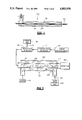
- FIG. 5 is a partial block diagram and partial pictorial view of another embodiment of an interface according to the present invention.
- FIG. 6 is a simplified pictorial illustration of a portion of an interface according to the present invention connected to a suitable gas phase detector.
- FIG. 7 is a pictorial view of a portion of an interface according to the present invention for depositing the sample on a solid surface for subsequent analysis by a solid phase or gas phase detector.
- FIG. 8 illustrates a portion of an interface according to the present invention for coupling LC to electron impact mass spectrometry analysis.
- FIG. 9 illustrates a portion of the interface according to the present invention for coupling LC to chemical ionization mass spectrometry analysis.
- FIG. 10 is a pictorial view of a portion of an interface according to the present invention for coupling LC to a temperature controlled surface for laser desorption analysis.
- the method and apparatus of the present invention are suitable for coupling LC effluent to various GC detectors.
- various conventional means may be used for vaporizing the particles even if thermal degradation of a sample occurs.
- Other detectors such as mass spectrometry and FTIR, provide information regarding molecular weight and/or molecular structure, and accordingly it is essential to avoid pyrolysis or other uncontrolled chemical modification of the sample.
- gas phase detectors which may be used with the interface of the present invention are flame ionization detectors (FID), flame photometric detectors (FPD) for specific elements (such as P and S), thermionic ionization detectors (TID), atomic absorption (AA), photoionization, thermal conductivity, mass spectrometry, inductively coupled plasma detectors (ICP), and Fourier transform infra-red (FTIR).
- FID flame ionization detectors
- FPD flame photometric detectors
- TID thermionic ionization detectors
- AA atomic absorption
- photoionization thermal conductivity
- mass spectrometry ICP
- ICP inductively coupled plasma detectors
- FTIR Fourier transform infra-red
- thermospray capillary a background discussion of vaporization and nebulization theory in a thermospray capillary is provided below.
- V v the effective vaporization velocity
- thermospray vaporizer shares many of the properties of a concentric pneumatic nebulizer used in atomic spectroscopy, in that a high velocity gas is used to shatter a liquid stream into a fine jet of droplets swept along in a gaseous stream.
- a significant feature of thermospray is that the nebulizing gas is generated in situ by partial vaporization of the liquid.
- Various attempts have been made to directly measure the droplet size distribution produced by thermospray, but these efforts have met with limited success primarily because a very large number of small, high velocity droplets are produced.
- the total number of droplets produced per second N d may be determined by the volume of the unvaporized liquid divided by the average volume of the droplets at the instant of nebulization from the bulk liquid. This relationship may be expressed as
- F is the liquid flow rate expressed in mL/min.
- f is the fraction vaporized
- d is the droplet diameter in microns.
- Equation 2 where r is the radius of the droplet, and V v is the net vaporization velocity calculated according to Equation 2. Since this rate is independent of r, the isothermal lifetime of a droplet can be expressed as a function of vaporization velocity. For water particles at 200° C. in the presence of water vapor at one atmosphere, the net velocity of vaporization is about 100 cm/sec. The isothermal lifetime of water droplets under these conditions is about 1 microsecond per micron radius. At 100° C., water droplets and its vapor at one atmosphere are in equilibrium, and the net rate of vaporization is zero. The very strong dependence of vaporization rates on temperature thus implies that the thermal environment of the droplet particles must be properly controlled for efficient vaporization and ion production.
- the parameters which affect the droplet lifetime within the interface of the invention are accordingly the thermospray vaporization parameters, namely the temperature of the jetstream from the vaporizer, the diameter of the droplets, and the temperature and pressure of the carrier gas added to the desolvation chamber, which then determines the heat transfer to the droplets. If the sample is expected to contain components only slightly less volatile than the solvent, it may be necessary to carefully adjust thermospray conditions for the interface to achieve satisfactory transmission of volatile sample components while simultaneously efficiently removing the solvent.
- FIG. 1 illustrates a block diagram of an interface according to the present invention.
- Effluent from a liquid chromatography (LC) unit 10 is directly coupled to a thermospray vaporizer 12, in which a controlled percentage of the solvent is vaporized while the remaining unvaporized solvent and sample particles are carried along as an aerosol in a high velocity vapor jet.
- the thermospray operation is carefully regulated by controller 14, which is described in detail in U.S. Pat. No. 4,730,111.
- the jet from the thermospray vaporizer 12 is introduced into a desolvation chamber 16, which may be heated sufficiently to further the vaporization process. Additional compressed and preferably inert gas, e.g.
- dry air, helium, or argon is added from source 18 to the chamber 16 in sufficient quantity to maintain the desired pressure and flow rate.
- the flow rate of carrier gas may be carefully regulated by valve 19, as described below.
- the temperature of the desolvation chamber is closely regulated by temperature controller 20, so that all or essentially all of the solvent is vaporized within the chamber 16.
- the thermospray technique of the present invention allows very precise control of vaporization, so that the solvent can be vaporized while all or substantially all of the less volatile particles of interest will be retained.
- An aerosol consisting of vaporized sample particles, solvent vapor, and inert carrier gas will exit the desolvation chamber 16 and pass through one or more solvent removal chambers 22, where most of the solvent vapor is removed and discharged to liquid waste container 24.
- the resulting dry aerosol (unvaporized sample particles and inert carrier gas) is then transmitted to the gas phase detector 28, either directly or through one or more particle beam separators.
- the gas phase detector may be responsive to the sample particles of interest or to vapor from the sample particles of interest. In the latter case, a vaporizer 27 is provided between the condensers and the detector to achieve varporization of the particles of interest.
- the temperature of the desolvation chamber 16 is closely controlled by controller 20, while the temperature of the solvent removal chamber(s) 22 is controlled by temperature controller 26 so that solvent is removed by condensation, and the dry aerosol continues to the selected detector.
- the solvent vapor is thus carefully condensed by regulating controller 26 and the condensed solvent passed to waste container 24 while the less volatile materials continue on unaffected by the condensation process.
- thermospray When thermospray is used to partially vaporize and nebulize the LC effluent, the desolvation 16 need not be controlled by a separate temperature controller 20, since the temperature of the spray in desolvation chamber 16 is sufficiently controlled by the vaporizer itself. For operation in this mode, it is preferable to operate the thermospray vaporizer close to, but below, the point of complete vaporization so that the vapor droplets exiting the vaporizer have sufficient heat content to provide the heat necessary to complete the vaporization during the expansion of the jet. Nevertheless, a separately heated desolvation chamber regulated by a controller 20 provides a convenient technique for completing the vaporization process started by the thermospray, and this temperature controlled desolvation chamber will often be required when using other types of nebulizers.
- FIG. 2 an embodiment of the interface is depicted in which the desolvation chamber employs a refrigerated condensor to remove the solvent vapor.
- the discharge end 30 of a thermospray vaporizer (which is fully described in U.S. Pat. No. 4,730,111) is installed in the desolvation chamber 34, such that a gas-tight connection is made between the vaporizer and the desolvation chamber. Controlled partial vaporization of solvent being discharged from end 30 is obtained by heater block 29 about the discharge end.
- the desolvation chamber 34 as shown in FIG.
- thermocouple 37 may thus be responsive to the temperature within chamber 34, to the temperature of the tube 40 in the heated zone of the desolvation chamber (as shown in FIG. 2), or to the temperature of the block 36.
- the output from thermocouple 37 is thus input to temperature controller 20, which regulates the heating of 36 to obtain the desired vaporization.
- the zone of the interface heated by block 36 should be sufficiently long to allow the particles to approch their thermal equilibrium with the vapor phase.
- the minimum temperature for complete vaporization of the solvent is then the temperature at which the vapor pressure of the solvent is just greater than the partial pressure of the completely vaporized solvent at the particular flow rate of the liquid employed.
- effluent from the desolvation chamber 34 consists of nearly dry particles of unvaporized sample, solvent vapor at a partial pressure somewhat less than one half of the total pressure, and carrier gas.
- An appropriate carrier gas is introduced into the desolvation chamber 34 through port 38, and preferably flows in the annulus between the chamber interior sidewalls 35 and the vaporizer probe 30 to entrain the droplets produced in the thermospray jet.
- the carrier gas is thus moving axially with and surrounds the thermospray jet.
- the flow rate of the carrier gas should be at least equal to the vapor flow produced by the complete vaporization of the liquid input to the vaporizer. If the LC sample contains volatile components, however, it may be desirable to use a higher gas flow rate so that the liquid can be vaporized at a lower temperature.
- thermospray vaporizer 128 such as that depicted in FIG. 3 may be employed.
- the liquid from the chromatograph is carried through an inner capillary tube 130 which may be conveniently made from fused silica or from stainless steel hypodermic needle tubing.
- An outer tube 132 of stainless steel is heated directly by passing a current through it, and the heat input is controlled as described in detail in U.S. Pat. No. 4,730,111.
- the carrier gas is transmitted through the annular space 134 between the inner and outer tube. With this device, both the LC effluent and the carrier gas are heated and the high velocity of heated carrier gas discharged surrounding the thermospray jet 136 assists in dispersing and vaporizing the droplets in the jet.
- a tube 40 with a circular interior cross-section of a diameter approximating one centimeter is satisfactory for flow rates obtained with LC liquid inputs up to at least 2 mL/minute.
- a uniform cross-section of the flow path throughout the desolvation chamber and condensers is preferred, and sudden changes in the cross-section which would result in rapid expansion or contraction of the flow rate should be avoided.
- the aerosol may be passed through an arcuate path, as shown in FIG. 2, sharp bends in the flow path should be avoided so that particles do not impact the interior sidewalls of the tube 40 and accordingly may pass to the selected detector.
- essentially laminar flow is maintained in tube 40, and the aerosol is carried by the higher velocity carrier gas through the center of the tube, thereby allowing the particles to be transported along comparatively long distances with negligible losses.
- diffusion of the aerosol particles to the walls is small, while diffusion of solvent molecules in the carrier gas is relatively rapid.
- the tube 40 is thus provided with a transition region or section 41 between the heated zone of the desolvation chamber and the cooled zone of the condenser.
- the transition region 41 is arranged, as shown in FIG. 2, so that the liquid condensate 44 preferably flows under the affects of gravity to the drain 46 in the transition region 41 of tube 40, where the condensate is pumped away to waste.
- a small positive displacement pump 48 such as a peristaltic tubing pump, may be used to pump away the condensate without allowing a significant amount of gas or vapor to escape from the interface.
- the drain may be equipped with a conventional check valve 50 to prevent backflow of liquid in the event that the interior pressure of the interface should drop below the outside pressure.
- the vapor exiting the condenser approaches equilibrium with the liquid at the temperature of the condenser.
- a condenser employing a straight tube approximately 30 centimeters in length has been found to be satisfactory for LC liquid input flow rates up to 0.5 Ml/minute.
- the length of the flow path from the desolvation chamber to the condensers should be at least 30 times, and preferably at least 50 times, the diameter or width of the flow path. For applications at higher liquid flow rates, the total length of the cool zone should be increased in proportion to the maximum liquid flow anticipated.
- the condenser can be configured to cool the tube 40 arranged in a helical form, thereby effectively increasing the cooled length of the tube 40 without increasing the size of the condenser.
- a helical pattern for the tube 40 would also introduce some angular momentum into the flow, which can increase the effective diffusion coefficient and correspondingly increase the efficiency of the condenser.
- a relatively simple interface as depicted in FIG. 2 may provide efficient solvent removal for some LC to gas phase detector applications.
- the detector is an electron impact mass spectrometer equipped with a two-stage particle beam separator which further reduces solvent vapor transmission
- the combination of the interface and the particular detector may result in efficient solvent removal efficiency while transmitting more than one half of the sample particles.
- the embodiment shown in FIG. 2 may thus result in good detector sensitivity for many samples, even though there is still significant contribution to the low mass portion of the mass spectrum by ionization of solvent vapor.
- the condenser as depicted in FIG.
- the condensor of the present invention is able to remove substantially all, and preferably at least 90% of the solvent in the LC effluent which is discharged into the desolvation chamber.
- Solvent removal efficiency of more than 95% can be obtained by programming the temperature of the condenser according to the composition of the LC mobile phase. The temperature of the condenser should, however, not be less than the freezing point of the liquid mixture input, or solid waste build up in the condenser may clog the interface. Since it is often desirable to detect samples separated by liquid chromatography at concentrations at the part per billion level or even lower, a further reduction in solvent concentration beyond that obtainable with the interface as shown in FIG. 2 may be required for many applications.
- FIG. 4 depicts a system which will enable a further reduction in solvent vapor concentration compared to the interface as shown in FIG. 2.
- the interface as shown in FIG. 4 includes a first stage condenser 52, which may be structurally and functionally identical to that depicted in FIG. 2.
- a second stage condenser 54 is added in series to first stage condenser 52, with the second stage unit 54 being structurally similar to that shown in FIG. 2, but with no additional carrier gas or thermospray jet provided, and thus no heated zone or block 36.
- the second stage condenser 46 comprises a U-tube in series with the U-tube of the first stage condenser, a second stage drain, and a second stage cooled zone or jacket 42 downstream from the drain.
- An cyrogenic trap 56 as shown in FIG. 4 is then added in series after the second stage condenser 54, with its effluent passing to a suitable gas phase detector, such as an EI mass spectrometer 58.
- a suitable gas phase detector
- the first stage condenser 52 is preferably operated at a temperature just above the freezing point of the input solvent composition
- the second stage condenser 54 is preferably operated at a temperature just above the freezing point of the remaining solvent vapor composition transmitted by the first condenser, so that the second stage condenses without freezing the maximum amount of solvent vapor.
- the vapor and aerosol pass through a section of tube 0 maintained at ambient temperature. This allows any solvent which may have condensed on the particles in the first stage condensers 54 to be revaporized, and subsequently condensed off the particles in the second stage condenser 56 with most of the remaining vapor.
- the effluent from the second stage condenser 54 may be transported through tube 60 which is positioned within a sealed housing 62 immersed in a suitable coolant, such as a liquid nitrogen.
- a suitable coolant such as a liquid nitrogen.
- the housing 62 may thus contain a liquid nitrogen inlet 61 and an outlet 63 which maintain the tube 60 at a sufficiently low temperature to effectively remove most of the remaining solvent vapor.
- This cyrogenic trap 56 thus will cause almost all of the remaining solvent to be trapped in solid form on the inner surface of the tube.
- cyrogenic trap 56 cannot be operated continuously. However, since only a small amount of condensable material is transmitted to the trap 56 from the second stage condenser 54, it can be operated for extended period (more than 8 hours) until sufficient solid buildup on the inside of tube 60 has occurred to require its removal. Removal of the buildup may be accomplished by closing the valve 68 connecting the output of the trap 68 to the detector, and removing the nitrogen coolant. By allowing the trap to warm to room temperature and then opening the drain valve 64, the accumulated condensate will be blow out past check valve 66 to waste.
- the performance of the interface according to the present invention depends to some extent on the size of the particles produced. Smaller particles are easily accelerated in the spray nozzle, and are also more easily deflected by flowing gas streams downstream of a nozzle. On the other hand, larger particles are more difficult to accelerate and require higher carrier gas velocities to maintain them as an aerosol, but once accelerated are not easily deflected from the particle beam. In the absence of nonvolatile material other than the sample of interest in the liquid stream, the final diameter of the dry particle will depend on the sample concentration in the unvaporized liquid.
- This feature may have the undesirable effect that the sample transfer efficiency may depend on the final particle size and hence the concentration of the sample in the unvaporized liquid, so that there is non-linearity in the detector response, particularly at low sample concentrations.
- This undesirable effect may be avoided by adding to the mobile phase a low concentration of a material, e.g., urea, having lower volatility than the solvent, so that its concentration rather than that of the sample determines the final particle size. If this added material is selected so that the detector does not respond significantly due to its presence, then the desired linear detector response to samples of interest can be achieved, and high detector sensitivity maintained.
- the selected material may be chosen to enhance gas phase detection of selected types of compounds, while surpressing detection of compounds of little or no interest.
- FIG. 5 An alternative method for accomplishing solvent vapor removal is depicted in FIG. 5.
- the refrigerated condensors are replaced by a gas diffusion cell 140.
- a "wet aerosol" mixture 142 consisting of carrier gas, solvent vapor, and sample particles from the desolvation chamber 16 enters the diffusion cell 140, and a "dry aerosol” mixture 144 consisting substantially of carrier gas and sample particles of interest passes to the detector 146.
- the sample particles passing through the diffusion cell are separated from a supplemental carrier gas flow by a diffusion membrane 146.
- Gas preferably chemically identical to the carrier gas introduced to the desolvation chamber, is input from container 148 into the diffusion cell housing 150, and flows in the annulus 152 between the housing 150 and membrane 146 in a counterflow direction to the flow of particles through the diffusion cell.
- the flow rate of the counterflowing supplemental gas must be significantly greater than the flow rate of the wet aerosol mixture, and is preferably two or more times greater, so that at each point along the membrane 146 the concentration of solvent vapor in the counterflow gas is significantly lower than that in the wet aerosol.
- the flow rate of supplemental carrier gas 154 may be closely controlled by valve 156.
- the properties of the membrane 146 are not critical, and a variety of filter media have been used successfully.
- the membrane should be sufficiently permeable that the carrier gas and vapor can diffuse freely across it, yet be a sufficient barrier to flow that any net flow of gas through the membrane is relatively small, and so that no particles of interest pass therethrough.
- a membrane formed from a fibrous porous form of PTFE has been found to be satisfactory, and such a suitable material is commercially available under the tradename "ZITEX.”
- the above approach has the advantage over the refrigerated condensors since no expensive mechanical components, such as refrigerators and pumps, are required, but has a minor disadvantage in that a higher total flow of carrier gas is required.
- the effective area of the diffusion cell i.e., the area of membrane 146 separating the particles in the primary flow from the supplemental carrier gas 154, may be easily controlled to remove the desired amount of solvent vapor.
- the gas diffusion cell 140 may be used in series with the refrigerated condensors.
- the diffusion cell 140 may replace the cryogenic trap discussed previously and shown in FIG. 4, so that a combination of first and second stage refrigerated condensors 52 and 54 followed by a diffusion cell 140 provides the desired solvent removal.
- the sample may be treated as required by the properties of the particular detection device employed in order to attain maximum detection efficiency for the sample.
- gas phase detectors such as PID or FID
- the sample particles can be extensively heated in the gas stream and caused to impact on a heated surface, since pyrolysis is not detrimental and only a portion of sample need be converted to gas so that it may be detected.
- additional conventional elements may be required to complete the coupling between the interface and the paticular detector.
- the interface of the present invention may be effectively used for coupling LC effluent to a wide variety of detectors.
- FIG. 6 a portion of an interface 70 is shown which, in accordance with the foregoing description, converts aerosol samples 72 less volatile than the LC solvent into a particle beam 73 which is efficiently transmitted to a gas phase detector 28.
- Solvent vapor is efficiently removed and replaced with a carrier gas at essentionally atmospheric pressure, the added gas being suitable as a carrier gas for use with the particular selected detector.
- the aerosol from one or more condensers 22 may be directly input at atmospheric pressure through flow tube 74 to a selected gas phase detector 28, which is vented to atmosphere.
- FIG. 6 illustrates a flow tube 74 from one or a series of condensers 22, wherein the aerosol flow (rate of from 0.5 to 2.0 L/minute) is substantially restricted at nozzle 75, which discharges a particle beam through momentum separator 76 and into tube 80. Gas or vapor may thus be vented from separator 76 through vent line 78, so that the beam 73 in tube 80 is at substantially atmospheric pressure.
- the flow rate in the tube 80 may be restricted, for example, by entrance skimmer 81, so that the detector 28 may be vented to atmosphere at 84, with vent 84 discharging a small fraction, e.g. from 10 to 100 mL/min., of the flow rate from the condensers 22.
- the tube 80 depicted in FIG. 6 is shown with a sleeve-like heating unit 82 in thermal contact with tube 80 to vaporize the sample particles passing through the tube 80, and thus transmit a sample vapor to the detector 28.
- FIG. 7 depicts a portion of a thermospray interface according to the present invention coupled to a detector 28 which is responsive to sample deposited on a solid surface. Accordingly, the flow tube 74 from the condensers is restricted by nozzle 75 to discharge a particle beam 73 which impinges a moving or movable surface 86, such as a ribbon, plate, or drum.
- the sample separated by liquid chromatography are thus deposited at different locations on the moving surface 86, and can subsequently be analyzed or detected by an appropriate surface sensitive technique, such as diffuse reflectance FTIR, secondary ion mass spectrometry (SIMS) or Cf-252 plasma desorption mass spectrometry.
- an appropriate surface sensitive technique such as diffuse reflectance FTIR, secondary ion mass spectrometry (SIMS) or Cf-252 plasma desorption mass spectrometry.
- a solid may be added in solution to the mobile phase upstream of the vaporizer, which can then serve as a solid carrier to enhance the transmission of samples of low concentration to the detector 28, and also enhance detection of the samples of interest.
- potassium chloride could be added to provide a transparent matrix for FTIR detection.
- organic solids such as nitrocellulose or tartaric acid, may be added upstream of the vaporizor to enhance the performance of a mass spectrometry detector.
- FIG. 8 illustrates a thermospray interface according to the present invention used to couple liquid chromatography to electron impact mass spectrometry. Since EI mass spectrometry requires a relatively good vacuum in the ion source and mass analyzer, additional pumping capability is provided to reduce the pressure of the carrier gas before it reaches the ion source, while simultaneously efficiently transmitting the particle beam. As illustrated in FIG. 8, tandem momentum separators are employed, and the selected carrier gas is preferably a low molecular weight inert gas, such as helium.
- the discharge from flow tube 74 passes through a first momentum separator 88, which is evacuated to a pressure of a few torr by a suitable mechanical vacuum pump 96 with the capacity of approximately 4 liters per second.
- the particle beam continues to pass through tube 92, with the flow rate further reduced by skimmer 81 as previously described, and is discharged into a second momentum separator 94 evacuated to a pressure of about 0.001 torr or less by a diffusion pump 96 with a capacity of about 400 liters per second.
- a second momentum separator 94 evacuated to a pressure of about 0.001 torr or less by a diffusion pump 96 with a capacity of about 400 liters per second.
- a small fraction of the carrier gas may, of course, reach the ion source 98, but a low mass and small ionization cross-section carrier gas (e.g. helium) in small concentration will not seriously degrade the performance of the EI mass spectrometer, e.g. when its pressure is less than about 0.0001 torr.
- the EI ion source 98 and mass analyzer 100 may be conveniently housed within chamber 102, in which vacuum is effectively controlled to the extent desired for EI mass spectrometry by pump 104.
- FIG. 9 depicts a thermospray interface for coupling liquid chromatography to chemical ionization mass spectrometry.
- This technique is similar to that employed for EI mass spectrometry, but only a single momentum separator is required, since the CI ion source 106 operates at a much higher pressure of, for example, 1 torr.
- the aerosol thus passes through a single momentum separator 88 as shown in FIG. 8, with the particle beam 73 continuing through tube 92A similar to that shown in FIG. 8. In this case, however, the particle beam is directly input to CI ion source 106, and the ions passed through baffles 108 and analyzed by mass analyzer 100A.
- the CI ion source 106 and analyzer 100A are appropriately housed in chamber 102A, with the necessary vacuum for CI mass spectrometry regulated by pump 104A.
- a desired chemical ionization reagent gas may be introduced with the carrier gas to the interface, or helium can be used as the carrier gas and the reagent introduced directly into the ion source 106 at a very low flow rate.
- FIG. 9 depicts a thermospray interface for transmitting a sample particle beam to a surface in an evacuated detection instrument.
- the detector in the particular configuration depicted is for laser desorption mass spectrometry, although secondary ion mass spectrometry, matrix isolation FTIR, or other detector requiring a high vacuum may be used.
- FTIR argon may be used as the carrier gas so that a small fraction of the transmitted gas impacts a cyrogenically cooled surface upon which both the sample and the gas are condensed and subsequently analyzed.
- the impacted surface may be either heated or cooled, and the sample contained in the particle beam 73 may be collected on the surface and simultaneously vaporized, or ionized by either focused laser radiation or by impact from high energy ions or neutrals.
- the samples may be vaporized by heating the surface, either directly or by irradiation from a laser or ion beam, and the samples then vaporized and ionized by electronic impact using auxillary electron beam techniques.
- FIG. 10 thus depicts a flow tube 92B similar to that previously described for receiving aerosol passed through a single momentum separator 88, and transmitting the particle beam 73 to a second momentum separator 94A with its vacuum maintained by vacuum pump 96A.
- the particle beam continues on to impact temperature controlled surface 118, where the sample is vaporized and ionized by laser beam 120 input to chamber 114 through port 122.
- the sample ions 126 pass through baffles 124, and thence to mass analyzer 100C. Appropriate vacuum for the analysis is maintained by pump 116.
- thermospray techniques which include the controlled partial vaporization of the effluent prior to discharge are preferred.
- thermospray techniques which include the controlled partial vaporization of the effluent prior to discharge are preferred.
- the techniques of the present invention are applicable, however, to various nebulizers for discharging LC effluent into the desolvation chamber, such as variations of the MAGIC or thermabeam concepts discussed earlier.
- a particular solvent may be selected for carrying the samples of interest (solute) through the chromatographic device which will be dependent upon the selected chromatographic unit and the samples to be separated by the process.
- a particular solvent may be selected for carrying the samples of interest (solute) through the chromatographic device which will be dependent upon the selected chromatographic unit and the samples to be separated by the process.
- gas phase and solid phase detectors may be used with the substantially universal interface of the present invention for coupling LC effluent to a desired detector.
- the same basic interface may be used with various gas phase detectors, thereby enhancing versatility of the interface and reducing manufacturing costs.
Abstract
Description
Claims (55)
Priority Applications (5)
| Application Number | Priority Date | Filing Date | Title |
|---|---|---|---|
| US07/285,516 US4883958A (en) | 1988-12-16 | 1988-12-16 | Interface for coupling liquid chromatography to solid or gas phase detectors |
| CA002002688A CA2002688A1 (en) | 1988-12-16 | 1989-11-10 | Interface for coupling liquid chromatography to solid or gas phase detectors |
| GB8927736A GB2226882B (en) | 1988-12-16 | 1989-12-07 | Interface for coupling liquid chromatography to solid or gas phase detectors |
| JP1322770A JPH02218955A (en) | 1988-12-16 | 1989-12-14 | Interface for connecting liquid chromatography to solid gaseous phase detector |
| DE3941533A DE3941533A1 (en) | 1988-12-16 | 1989-12-15 | INTERFACE FOR PAIRING LIQUID CHROMATOGRAPHY WITH SOLID OR GAS PHASE DETECTORS |
Applications Claiming Priority (1)
| Application Number | Priority Date | Filing Date | Title |
|---|---|---|---|
| US07/285,516 US4883958A (en) | 1988-12-16 | 1988-12-16 | Interface for coupling liquid chromatography to solid or gas phase detectors |
Publications (1)
| Publication Number | Publication Date |
|---|---|
| US4883958A true US4883958A (en) | 1989-11-28 |
Family
ID=23094585
Family Applications (1)
| Application Number | Title | Priority Date | Filing Date |
|---|---|---|---|
| US07/285,516 Expired - Fee Related US4883958A (en) | 1988-12-16 | 1988-12-16 | Interface for coupling liquid chromatography to solid or gas phase detectors |
Country Status (5)
| Country | Link |
|---|---|
| US (1) | US4883958A (en) |
| JP (1) | JPH02218955A (en) |
| CA (1) | CA2002688A1 (en) |
| DE (1) | DE3941533A1 (en) |
| GB (1) | GB2226882B (en) |
Cited By (77)
| Publication number | Priority date | Publication date | Assignee | Title |
|---|---|---|---|---|
| US4982089A (en) * | 1990-02-28 | 1991-01-01 | The United States Of America As Represented By The Secretary Of The Army | Method for obtaining the spectra of an unstable product |
| US5160840A (en) * | 1991-10-25 | 1992-11-03 | Vestal Marvin L | Time-of-flight analyzer and method |
| EP0512394A2 (en) * | 1991-05-02 | 1992-11-11 | Waters Investments Limited | Method and apparatus for analyzing sample solutions |
| WO1993003493A1 (en) * | 1991-08-01 | 1993-02-18 | The Dow Chemical Company | Interfacing liquid chromatograph and fourier transform |
| US5192865A (en) * | 1992-01-14 | 1993-03-09 | Cetac Technologies Inc. | Atmospheric pressure afterglow ionization system and method of use, for mass spectrometer sample analysis systems |
| US5259254A (en) * | 1991-09-25 | 1993-11-09 | Cetac Technologies, Inc. | Sample introduction system for inductively coupled plasma and other gas-phase, or particle, detectors utilizing ultrasonic nebulization, and method of use |
| US5266192A (en) * | 1991-09-12 | 1993-11-30 | General Electric Company | Apparatus for interfacing liquid chromatograph with magnetic sector spectrometer |
| GB2274940A (en) * | 1993-01-22 | 1994-08-10 | Hewlett Packard Co | Liquid chromatography/mass spectrometer adaptable for electrospray or particle beam operation |
| US5345079A (en) * | 1992-03-10 | 1994-09-06 | Mds Health Group Limited | Apparatus and method for liquid sample introduction |
| US5359196A (en) * | 1993-05-24 | 1994-10-25 | Hewlett-Packard Company | Mass spectrometry with gas counterflow for particle beam |
| US5448062A (en) * | 1993-08-30 | 1995-09-05 | Mims Technology Development Co. | Analyte separation process and apparatus |
| US5454274A (en) * | 1991-09-25 | 1995-10-03 | Cetac Technologies Inc. | Sequential combination low temperature condenser and enclosed filter solvent removal system, and method of use |
| US5538643A (en) * | 1991-08-01 | 1996-07-23 | The Dow Chemical Company | Continuous flow apparatus and method for interfacing liquid chromatograph and fourier transform infrared spectrometer |
| US5554540A (en) * | 1995-01-19 | 1996-09-10 | Hewlett-Packard Company | Method and apparatus for preserving the sensitivity of a thermionic ionization detector |
| US5559326A (en) * | 1995-07-28 | 1996-09-24 | Hewlett-Packard Company | Self generating ion device for mass spectrometry of liquids |
| US5572023A (en) * | 1995-05-30 | 1996-11-05 | Board Of Regents, The University Of Texas System | Electrospray methods and apparatus for trace analysis |
| US5625184A (en) * | 1995-05-19 | 1997-04-29 | Perseptive Biosystems, Inc. | Time-of-flight mass spectrometry analysis of biomolecules |
| US5723091A (en) * | 1995-01-23 | 1998-03-03 | Hewlett-Packard Co. | Flow modulation for facilitating detector ignition |
| WO1998023952A1 (en) * | 1996-11-26 | 1998-06-04 | Anglo American Research Laboratories (Proprietary) Limited | Nebulizer |
| US5772964A (en) * | 1996-02-08 | 1998-06-30 | Lab Connections, Inc. | Nozzle arrangement for collecting components from a fluid for analysis |
| US5853664A (en) * | 1996-06-25 | 1998-12-29 | Hewlett-Packard Company | Flow modulation for facilitating detector ignition |
| US6002127A (en) * | 1995-05-19 | 1999-12-14 | Perseptive Biosystems, Inc. | Time-of-flight mass spectrometry analysis of biomolecules |
| WO2000055600A2 (en) * | 1999-02-25 | 2000-09-21 | Clemson University | Sampling and analysis of airborne particulate matter by glow discharge atomic emission and mass spectrometries |
| EP1067379A1 (en) * | 1998-03-23 | 2001-01-10 | Alexandr Akhatovich Ganeev | Method for detecting elements in solutions and device for realising the same |
| WO2002018939A2 (en) * | 2000-09-02 | 2002-03-07 | Phlogiston Scientific Limited | Analyte detection system |
| US6358692B1 (en) | 1995-06-26 | 2002-03-19 | Perseptive Biosystems, Inc. | High speed, automated, continuous flow, multi-dimensional molecular selection and analysis |
| US6465776B1 (en) | 2000-06-02 | 2002-10-15 | Board Of Regents, The University Of Texas System | Mass spectrometer apparatus for analyzing multiple fluid samples concurrently |
| US20020166961A1 (en) * | 2001-03-29 | 2002-11-14 | Berggren William Travis | Droplet ion source for mass spectrometry |
| US6534765B1 (en) * | 1999-10-29 | 2003-03-18 | Mds Inc. | Atmospheric pressure photoionization (APPI): a new ionization method for liquid chromatography-mass spectrometry |
| US6566652B1 (en) * | 1999-09-13 | 2003-05-20 | Hitachi, Ltd. | Mass spectrometry apparatus having ion source not at negative pressure when finishing measurement |
| FR2856939A1 (en) * | 2003-07-03 | 2005-01-07 | Jobin Yvon Sas | Gas humidifier, particularly for samples entering atomic emission spectrometer, comprises receiver for liquid water, inlet port and outlet port |
| US6933496B2 (en) * | 2000-06-23 | 2005-08-23 | The Regents Of The University Of California | Ion mobility sensor |
| EP1752766A1 (en) * | 2005-08-10 | 2007-02-14 | Agilent Technologies, Inc. | Concentration techniques in chromatographic separation |
| US20070102634A1 (en) * | 2005-11-10 | 2007-05-10 | Frey Brian L | Electrospray ionization ion source with tunable charge reduction |
| US20080252886A1 (en) * | 2005-09-22 | 2008-10-16 | Avantium International B.V. | System and Method for Solubility Curve and Metastable Zone Determination |
| US20080272287A1 (en) * | 2007-05-01 | 2008-11-06 | Vestal Marvin L | High Performance Low Cost MALDI MS-MS |
| US20080272289A1 (en) * | 2007-05-01 | 2008-11-06 | Vestal Marvin L | Linear tof geometry for high sensitivity at high mass |
| US20080272286A1 (en) * | 2007-05-01 | 2008-11-06 | Vestal Marvin L | Vacuum Housing System for MALDI-TOF Mass Spectrometry |
| US20080272293A1 (en) * | 2007-05-01 | 2008-11-06 | Vestal Marvin L | Reversed Geometry MALDI TOF |
| US20080272291A1 (en) * | 2007-05-01 | 2008-11-06 | Vestal Marvin L | Tof-tof with high resolution precursor selection and multiplexed ms-ms |
| US7589319B2 (en) | 2007-05-01 | 2009-09-15 | Virgin Instruments Corporation | Reflector TOF with high resolution and mass accuracy for peptides and small molecules |
| WO2009117312A2 (en) * | 2008-03-19 | 2009-09-24 | Waters Technologies Corporation | Apparatus and methods for making analyte particles |
| US20090272204A1 (en) * | 2008-04-30 | 2009-11-05 | Symrise Gmbh & Co., Kg | Device and process for reducing an ethanol content of a liquid preparation |
| US20100000943A1 (en) * | 2006-12-08 | 2010-01-07 | Carson William W | Method and apparatus for desolvating flowing liquid |
| US20110064616A1 (en) * | 2009-09-17 | 2011-03-17 | Yury Zelechonok | Transport detector for liquid chromatography |
| US20110195519A1 (en) * | 2010-01-21 | 2011-08-11 | Ralph Sturgeon | Thin-film photochemical vapour generation |
| US8305582B2 (en) | 2009-09-01 | 2012-11-06 | Alltech Associates, Inc. | Methods and apparatus for analyzing samples and collecting sample fractions |
| US8305581B2 (en) | 2007-12-05 | 2012-11-06 | Alltech Associates, Inc. | Methods and apparatus for analyzing samples and collecting sample fractions |
| US8414684B2 (en) | 2010-06-01 | 2013-04-09 | Dionex Corporation | High pressure degas assembly for chromatography system and method |
| CN103977925A (en) * | 2014-05-23 | 2014-08-13 | 国家海洋局天津海水淡化与综合利用研究所 | Device and method for measuring and controlling sprinkle density |
| US9086422B2 (en) | 2008-12-10 | 2015-07-21 | Alltech Associates, Inc. | Chromatography systems and system components |
| US20160059249A1 (en) * | 2014-08-26 | 2016-03-03 | Tsi, Inc. | Electrospray with soft x-ray neutralizer |
| US9536725B2 (en) | 2013-02-05 | 2017-01-03 | Clemson University | Means of introducing an analyte into liquid sampling atmospheric pressure glow discharge |
| US20170148617A1 (en) * | 2015-11-20 | 2017-05-25 | Hitachi High-Tech Science Corporation | Method for analyzing evolved gas and evolved gas analyzer |
| US20170146497A1 (en) * | 2015-11-20 | 2017-05-25 | Hitachi High-Tech Science Corporation | Method for correcting evolved gas analyzer and evolved gas analyzer |
| US20170148616A1 (en) * | 2015-11-20 | 2017-05-25 | Hitachi High-Tech Science Corporation | Method for analyzing evolved gas and evolved gas analyzer |
| US9754773B1 (en) | 2016-05-12 | 2017-09-05 | Thermo Finnigan Llc | Internal solvent trap with drain |
| CN109414650A (en) * | 2016-06-30 | 2019-03-01 | 史密斯探测公司 | The air-flow assisting ion transfer system that transfer efficiency improves |
| US10777397B2 (en) | 2015-03-06 | 2020-09-15 | Micromass Uk Limited | Inlet instrumentation for ion analyser coupled to rapid evaporative ionisation mass spectrometry (“REIMS”) device |
| US10777398B2 (en) | 2015-03-06 | 2020-09-15 | Micromass Uk Limited | Spectrometric analysis |
| US10916415B2 (en) * | 2015-03-06 | 2021-02-09 | Micromass Uk Limited | Liquid trap or separator for electrosurgical applications |
| US10978284B2 (en) | 2015-03-06 | 2021-04-13 | Micromass Uk Limited | Imaging guided ambient ionisation mass spectrometry |
| US11031222B2 (en) | 2015-03-06 | 2021-06-08 | Micromass Uk Limited | Chemically guided ambient ionisation mass spectrometry |
| US11031223B2 (en) | 2015-09-29 | 2021-06-08 | Micromass Uk Limited | Capacitively coupled REIMS technique and optically transparent counter electrode |
| US11037774B2 (en) | 2015-03-06 | 2021-06-15 | Micromass Uk Limited | Physically guided rapid evaporative ionisation mass spectrometry (“REIMS”) |
| US11139156B2 (en) | 2015-03-06 | 2021-10-05 | Micromass Uk Limited | In vivo endoscopic tissue identification tool |
| US20220011201A1 (en) * | 2018-12-13 | 2022-01-13 | Elementar Analysensysteme Gmbh | Method and an apparatus for determining isotope relationships |
| US11239066B2 (en) | 2015-03-06 | 2022-02-01 | Micromass Uk Limited | Cell population analysis |
| US11264223B2 (en) | 2015-03-06 | 2022-03-01 | Micromass Uk Limited | Rapid evaporative ionisation mass spectrometry (“REIMS”) and desorption electrospray ionisation mass spectrometry (“DESI-MS”) analysis of swabs and biopsy samples |
| US11270876B2 (en) | 2015-03-06 | 2022-03-08 | Micromass Uk Limited | Ionisation of gaseous samples |
| US11282688B2 (en) | 2015-03-06 | 2022-03-22 | Micromass Uk Limited | Spectrometric analysis of microbes |
| US11289320B2 (en) | 2015-03-06 | 2022-03-29 | Micromass Uk Limited | Tissue analysis by mass spectrometry or ion mobility spectrometry |
| US11342170B2 (en) | 2015-03-06 | 2022-05-24 | Micromass Uk Limited | Collision surface for improved ionisation |
| US11367605B2 (en) | 2015-03-06 | 2022-06-21 | Micromass Uk Limited | Ambient ionization mass spectrometry imaging platform for direct mapping from bulk tissue |
| US11406916B2 (en) * | 2015-03-18 | 2022-08-09 | Francois Parmentier | Method of power-efficient chromatographic separation |
| US11454611B2 (en) | 2016-04-14 | 2022-09-27 | Micromass Uk Limited | Spectrometric analysis of plants |
| US11476105B2 (en) * | 2020-03-19 | 2022-10-18 | The Government Of The United States Of America, As Represented By The Secretary Of The Navy | Concentric permeation system for transfer of neutral gaseous material |
Families Citing this family (2)
| Publication number | Priority date | Publication date | Assignee | Title |
|---|---|---|---|---|
| DE102008022347B4 (en) | 2008-04-30 | 2018-11-22 | Symrise Ag | Apparatus, use of the apparatus and method for producing a liquid flavor condensate |
| KR20110116011A (en) * | 2008-12-10 | 2011-10-24 | 올테크 어소시에이츠, 인크. | Components suitable for use in devices such as an evaporative light scattering detector |
Citations (15)
| Publication number | Priority date | Publication date | Assignee | Title |
|---|---|---|---|---|
| US4055987A (en) * | 1976-03-04 | 1977-11-01 | Finnigan Corporation | Liquid chromatograph/mass spectrometer interface |
| US4112297A (en) * | 1976-06-30 | 1978-09-05 | Hitachi, Ltd. | Interface for use in a combined liquid chromatography - mass spectrometry system |
| US4298795A (en) * | 1978-09-08 | 1981-11-03 | Japan Spectroscopic Co. Ltd | Method and apparatus for introducing samples to a mass spectrometer |
| US4403147A (en) * | 1979-05-25 | 1983-09-06 | Hewlett-Packard Company | Apparatus for analyzing liquid samples with a mass spectrometer |
| US4531056A (en) * | 1983-04-20 | 1985-07-23 | Yale University | Method and apparatus for the mass spectrometric analysis of solutions |
| JPS61107156A (en) * | 1984-10-31 | 1986-05-26 | Jeol Ltd | Discrimination method relating to alcoholic beverage |
| US4629478A (en) * | 1984-06-22 | 1986-12-16 | Georgia Tech Research Corporation | Monodisperse aerosol generator |
| US4647772A (en) * | 1984-02-22 | 1987-03-03 | Vg Instruments Group Limited | Mass spectrometers |
| US4730111A (en) * | 1983-08-30 | 1988-03-08 | Research Corporation | Ion vapor source for mass spectrometry of liquids |
| US4731533A (en) * | 1986-10-15 | 1988-03-15 | Vestec Corporation | Method and apparatus for dissociating ions by electron impact |
| US4766312A (en) * | 1987-05-15 | 1988-08-23 | Vestec Corporation | Methods and apparatus for detecting negative ions from a mass spectrometer |
| US4791292A (en) * | 1986-04-24 | 1988-12-13 | The Dow Chemical Company | Capillary membrane interface for a mass spectrometer |
| US4814612A (en) * | 1983-08-30 | 1989-03-21 | Research Corporation | Method and means for vaporizing liquids for detection or analysis |
| US4820648A (en) * | 1985-08-21 | 1989-04-11 | Spectros Limited | Methods for use in the mass analysis of chemical samples |
| JPH102553A (en) * | 1996-06-14 | 1998-01-06 | Sanyo Electric Co Ltd | Kerosene boiler |
Family Cites Families (2)
| Publication number | Priority date | Publication date | Assignee | Title |
|---|---|---|---|---|
| GB2203241B (en) * | 1987-03-06 | 1991-12-04 | Extrel Corp | Introduction of effluent into mass spectrometers and other gas-phase or particle detectors |
| GB2240176B (en) * | 1987-03-06 | 1991-12-04 | Extrel Corp | Introduction of effluent into mass spectrometers and other gas-phase or particle detectors |
-
1988
- 1988-12-16 US US07/285,516 patent/US4883958A/en not_active Expired - Fee Related
-
1989
- 1989-11-10 CA CA002002688A patent/CA2002688A1/en not_active Abandoned
- 1989-12-07 GB GB8927736A patent/GB2226882B/en not_active Expired - Fee Related
- 1989-12-14 JP JP1322770A patent/JPH02218955A/en active Pending
- 1989-12-15 DE DE3941533A patent/DE3941533A1/en not_active Withdrawn
Patent Citations (15)
| Publication number | Priority date | Publication date | Assignee | Title |
|---|---|---|---|---|
| US4055987A (en) * | 1976-03-04 | 1977-11-01 | Finnigan Corporation | Liquid chromatograph/mass spectrometer interface |
| US4112297A (en) * | 1976-06-30 | 1978-09-05 | Hitachi, Ltd. | Interface for use in a combined liquid chromatography - mass spectrometry system |
| US4298795A (en) * | 1978-09-08 | 1981-11-03 | Japan Spectroscopic Co. Ltd | Method and apparatus for introducing samples to a mass spectrometer |
| US4403147A (en) * | 1979-05-25 | 1983-09-06 | Hewlett-Packard Company | Apparatus for analyzing liquid samples with a mass spectrometer |
| US4531056A (en) * | 1983-04-20 | 1985-07-23 | Yale University | Method and apparatus for the mass spectrometric analysis of solutions |
| US4730111A (en) * | 1983-08-30 | 1988-03-08 | Research Corporation | Ion vapor source for mass spectrometry of liquids |
| US4814612A (en) * | 1983-08-30 | 1989-03-21 | Research Corporation | Method and means for vaporizing liquids for detection or analysis |
| US4647772A (en) * | 1984-02-22 | 1987-03-03 | Vg Instruments Group Limited | Mass spectrometers |
| US4629478A (en) * | 1984-06-22 | 1986-12-16 | Georgia Tech Research Corporation | Monodisperse aerosol generator |
| JPS61107156A (en) * | 1984-10-31 | 1986-05-26 | Jeol Ltd | Discrimination method relating to alcoholic beverage |
| US4820648A (en) * | 1985-08-21 | 1989-04-11 | Spectros Limited | Methods for use in the mass analysis of chemical samples |
| US4791292A (en) * | 1986-04-24 | 1988-12-13 | The Dow Chemical Company | Capillary membrane interface for a mass spectrometer |
| US4731533A (en) * | 1986-10-15 | 1988-03-15 | Vestec Corporation | Method and apparatus for dissociating ions by electron impact |
| US4766312A (en) * | 1987-05-15 | 1988-08-23 | Vestec Corporation | Methods and apparatus for detecting negative ions from a mass spectrometer |
| JPH102553A (en) * | 1996-06-14 | 1998-01-06 | Sanyo Electric Co Ltd | Kerosene boiler |
Non-Patent Citations (62)
| Title |
|---|
| "A Comparison Between Thermospray and Particle Beam LC/MS for Environmental Applications", Apffel et al., 7/88, Symposium on Waste Testing & Quality Assurance. |
| "An Improved Thermospray LC/C1/E1 Ion Source for Structural Elucidation in Combined Liquid Chromatography/Mass Spectrometry", Vestal et al., Abst. No. 253. |
| "Analysis of Drugs of Abuse by Particle Beam LC/MS", Apffel et al., 6/88, 36th ASMS Conference on Mass Spectrometry and Allied Topics. |
| "Capillary Diameter Effects on Thermospray Sample Introduction to ICP-AES", Koropchak et al., 1/88, Winter Conference on Plasma Spectrochemical Analysis. |
| "Chromatographic Performance and Applications of the MAGIC LC/MS Interface", Harris et al., Abstract No. 250. |
| "Comparison of Different Absorbance Detection Techniques LC-UV-MS", Dourdeville et al., Abstract No. 252. |
| "Design of a New Liquid Chromatographic System for LC-UV-MS", Cassis et al., Abstract No. 256. |
| "Determination of Spent Solvent Wastes in Water By Thermospray Liquid Chromatography-Mass Spectrometry", Vestal, Abstract No. 1260. |
| "Electron Impact Ionization Mass Spectra of Polystyrene Oligomers by Thermabeam LC/MS", Jones, 6/88, 36th ASMS Conference on Mass Spectrometry and Allied. |
| "Electron Impact Mass Spectra with Thermabeam LC/MS", Willoughby et al., Abstract No. 255. |
| "Evaluation of Thermospray Liquid Chromatography-Mass Spectrometry for Drugs of Abuse", Vestal, Abstract No. 669. |
| "Fundamental Studies of High Efficiency Sputtering System for Atomic Spectroscopy", Piepmeier et al., Abstract No. 760. |
| "Improvements in a Particle Beam LC/MS Interface", Apffel, et al., 6/88, 36th ASMS Conference on Mass Spectrometry and Allied Topics. |
| "Integrated Thermospray and Thermabeam Sample Introduction for LC/MS and SFC/MS", Buchner, Abstract No. 257. |
| "Ion Spray LC/MS Determination of Neuro Peptides with Atmospheric Pressure Ionization", Lee et al., Abstract No. 251. |
| "Legally Defensible Data on Drugs of Abuse by Thermabeam LC/MS", Pizzitola et al., Abstract No. 668. |
| "LSMIS of Intact Oligosaccharides: Comparison of Sensitivity and Spectral Quality Among Selected Derivatives", Poulter et al., 6/88, 36th ASMS Conference. |
| "MAGIC: Basic Studies in Transport and Transport Efficiency", Kirk et al., Abstract No. 249. |
| "Monodisperse Aerosol Generation Interface for Combining Liquid Chromatography with Mass Spectroscopy", Willoughby et al., School of Chemistry, Georgia. |
| "New Ways to Get Excited with LC/MS and Environmentally Significant Compounds", Pizzitola et al., Abstract No. 1261. |
| "Particle Beam Liquid Chromatography Mass Spectrometry (PB/LC/MS): A New Technique Applied to Determinations of Environmental, Forensic and Defense Interest", Sauter et al., Abstract No. 759. |
| "Particle Concentration Fluorescence Immunoassay for Tissue Plasminogen Activator", Sportsman et al., Abstract No. 329. |
| "Polymeric Fluorenyl Reagent for the Derivatization of Polyamines in Biological Fluids", Chou et al., Abstract No. 247. |
| "Positive-and Negative-Ion Chemical Ionization Mass Spectrometry of Aldicarb and its Derivatives by Particle Beam HPLC/MS", Lynn, et al., 6/88, 36th ASMS Conf. |
| "Revenants in Chemical Analysis", Lodder et al., Abstract No. 258. |
| "Secondary Ion Mass Spectrometry of Solute Particle Beams by Thermabeam LC/MS", Willoughby et al., 36th ASMS Conference on Mass Spectrometry and Allied Topics. |
| "Solid Phase Extraction for Determination of Urea and Carbamate Pesticides in Ground Water", Englel et al., Abstract No. 1337. |
| "Structural Elucidation in Biomedical and Pharmaceutical Analysis via Mass Spectroscopy Using Thermabeam and Thermaspray LC/MS", Sheehan, Abstract #330. |
| "Studies of Anabolic Steroids by Thermabeam LC/MS", Dilts et al., 6/88, 36th ASMS Conference on Mass Spectrometry and Allied Topics. |
| "Supercritical Fluid Chromatographic/Mass Spectrometric Studies of Environmental Samples", Games et al., Abstract No. 248. |
| "Thermospray Interfacing for Flow Injection Analysis with Inductively Coupled Plasma Atomic Emission Spectrometry", Koropchak et al., 4/86. |
| A Comparison Between Thermospray and Particle Beam LC/MS for Environmental Applications , Apffel et al., 7/88, Symposium on Waste Testing & Quality Assurance. * |
| An Improved Thermospray LC/C1/E1 Ion Source for Structural Elucidation in Combined Liquid Chromatography/Mass Spectrometry , Vestal et al., Abst. No. 253. * |
| Analysis of Drugs of Abuse by Particle Beam LC/MS , Apffel et al., 6/88, 36th ASMS Conference on Mass Spectrometry and Allied Topics. * |
| Capillary Diameter Effects on Thermospray Sample Introduction to ICP AES , Koropchak et al., 1/88, Winter Conference on Plasma Spectrochemical Analysis. * |
| Chromatographic Performance and Applications of the MAGIC LC/MS Interface , Harris et al., Abstract No. 250. * |
| Comparison of Different Absorbance Detection Techniques LC UV MS , Dourdeville et al., Abstract No. 252. * |
| Design of a New Liquid Chromatographic System for LC UV MS , Cassis et al., Abstract No. 256. * |
| Determination of Spent Solvent Wastes in Water By Thermospray Liquid Chromatography Mass Spectrometry , Vestal, Abstract No. 1260. * |
| Electron Impact Ionization Mass Spectra of Polystyrene Oligomers by Thermabeam LC/MS , Jones, 6/88, 36th ASMS Conference on Mass Spectrometry and Allied. * |
| Electron Impact Mass Spectra with Thermabeam LC/MS , Willoughby et al., Abstract No. 255. * |
| Evaluation of Thermospray Liquid Chromatography Mass Spectrometry for Drugs of Abuse , Vestal, Abstract No. 669. * |
| Fundamental Studies of High Efficiency Sputtering System for Atomic Spectroscopy , Piepmeier et al., Abstract No. 760. * |
| Improvements in a Particle Beam LC/MS Interface , Apffel, et al., 6/88, 36th ASMS Conference on Mass Spectrometry and Allied Topics. * |
| Integrated Thermospray and Thermabeam Sample Introduction for LC/MS and SFC/MS , Buchner, Abstract No. 257. * |
| Ion Spray LC/MS Determination of Neuro Peptides with Atmospheric Pressure Ionization , Lee et al., Abstract No. 251. * |
| Legally Defensible Data on Drugs of Abuse by Thermabeam LC/MS , Pizzitola et al., Abstract No. 668. * |
| LSMIS of Intact Oligosaccharides: Comparison of Sensitivity and Spectral Quality Among Selected Derivatives , Poulter et al., 6/88, 36th ASMS Conference. * |
| MAGIC: Basic Studies in Transport and Transport Efficiency , Kirk et al., Abstract No. 249. * |
| Monodisperse Aerosol Generation Interface for Combining Liquid Chromatography with Mass Spectroscopy , Willoughby et al., School of Chemistry, Georgia. * |
| New Ways to Get Excited with LC/MS and Environmentally Significant Compounds , Pizzitola et al., Abstract No. 1261. * |
| Particle Beam Liquid Chromatography Mass Spectrometry (PB/LC/MS): A New Technique Applied to Determinations of Environmental, Forensic and Defense Interest , Sauter et al., Abstract No. 759. * |
| Particle Concentration Fluorescence Immunoassay for Tissue Plasminogen Activator , Sportsman et al., Abstract No. 329. * |
| Polymeric Fluorenyl Reagent for the Derivatization of Polyamines in Biological Fluids , Chou et al., Abstract No. 247. * |
| Positive and Negative Ion Chemical Ionization Mass Spectrometry of Aldicarb and its Derivatives by Particle Beam HPLC/MS , Lynn, et al., 6/88, 36th ASMS Conf. * |
| Revenants in Chemical Analysis , Lodder et al., Abstract No. 258. * |
| Secondary Ion Mass Spectrometry of Solute Particle Beams by Thermabeam LC/MS , Willoughby et al., 36th ASMS Conference on Mass Spectrometry and Allied Topics. * |
| Solid Phase Extraction for Determination of Urea and Carbamate Pesticides in Ground Water , Englel et al., Abstract No. 1337. * |
| Structural Elucidation in Biomedical and Pharmaceutical Analysis via Mass Spectroscopy Using Thermabeam and Thermaspray LC/MS , Sheehan, Abstract 330. * |
| Studies of Anabolic Steroids by Thermabeam LC/MS , Dilts et al., 6/88, 36th ASMS Conference on Mass Spectrometry and Allied Topics. * |
| Supercritical Fluid Chromatographic/Mass Spectrometric Studies of Environmental Samples , Games et al., Abstract No. 248. * |
| Thermospray Interfacing for Flow Injection Analysis with Inductively Coupled Plasma Atomic Emission Spectrometry , Koropchak et al., 4/86. * |
Cited By (119)
| Publication number | Priority date | Publication date | Assignee | Title |
|---|---|---|---|---|
| US4982089A (en) * | 1990-02-28 | 1991-01-01 | The United States Of America As Represented By The Secretary Of The Army | Method for obtaining the spectra of an unstable product |
| EP0512394A2 (en) * | 1991-05-02 | 1992-11-11 | Waters Investments Limited | Method and apparatus for analyzing sample solutions |
| EP0512394A3 (en) * | 1991-05-02 | 1993-01-20 | Millipore Corporation | Method and apparatus for analyzing sample solutions |
| WO1993003493A1 (en) * | 1991-08-01 | 1993-02-18 | The Dow Chemical Company | Interfacing liquid chromatograph and fourier transform |
| US5538643A (en) * | 1991-08-01 | 1996-07-23 | The Dow Chemical Company | Continuous flow apparatus and method for interfacing liquid chromatograph and fourier transform infrared spectrometer |
| US5266192A (en) * | 1991-09-12 | 1993-11-30 | General Electric Company | Apparatus for interfacing liquid chromatograph with magnetic sector spectrometer |
| US5454274A (en) * | 1991-09-25 | 1995-10-03 | Cetac Technologies Inc. | Sequential combination low temperature condenser and enclosed filter solvent removal system, and method of use |
| US5259254A (en) * | 1991-09-25 | 1993-11-09 | Cetac Technologies, Inc. | Sample introduction system for inductively coupled plasma and other gas-phase, or particle, detectors utilizing ultrasonic nebulization, and method of use |
| US5160840A (en) * | 1991-10-25 | 1992-11-03 | Vestal Marvin L | Time-of-flight analyzer and method |
| US5192865A (en) * | 1992-01-14 | 1993-03-09 | Cetac Technologies Inc. | Atmospheric pressure afterglow ionization system and method of use, for mass spectrometer sample analysis systems |
| US5345079A (en) * | 1992-03-10 | 1994-09-06 | Mds Health Group Limited | Apparatus and method for liquid sample introduction |
| GB2274940A (en) * | 1993-01-22 | 1994-08-10 | Hewlett Packard Co | Liquid chromatography/mass spectrometer adaptable for electrospray or particle beam operation |
| GB2274940B (en) * | 1993-01-22 | 1996-04-10 | Hewlett Packard Co | Combined electrospray/particle beam liquid chromatography/mass spectrometer |
| US5359196A (en) * | 1993-05-24 | 1994-10-25 | Hewlett-Packard Company | Mass spectrometry with gas counterflow for particle beam |
| US5448062A (en) * | 1993-08-30 | 1995-09-05 | Mims Technology Development Co. | Analyte separation process and apparatus |
| US5554540A (en) * | 1995-01-19 | 1996-09-10 | Hewlett-Packard Company | Method and apparatus for preserving the sensitivity of a thermionic ionization detector |
| US5723091A (en) * | 1995-01-23 | 1998-03-03 | Hewlett-Packard Co. | Flow modulation for facilitating detector ignition |
| US6057543A (en) * | 1995-05-19 | 2000-05-02 | Perseptive Biosystems, Inc. | Time-of-flight mass spectrometry analysis of biomolecules |
| US5625184A (en) * | 1995-05-19 | 1997-04-29 | Perseptive Biosystems, Inc. | Time-of-flight mass spectrometry analysis of biomolecules |
| US5627369A (en) * | 1995-05-19 | 1997-05-06 | Perseptive Biosystems, Inc. | Time-of-flight mass spectrometry analysis of biomolecules |
| US5760393A (en) * | 1995-05-19 | 1998-06-02 | Perseptive Biosystems, Inc. | Time-of-flight mass spectrometry analysis of biomolecules |
| US20040079878A1 (en) * | 1995-05-19 | 2004-04-29 | Perseptive Biosystems, Inc. | Time-of-flight mass spectrometry analysis of biomolecules |
| US6541765B1 (en) | 1995-05-19 | 2003-04-01 | Perseptive Biosystems, Inc. | Time-of-flight mass spectrometry analysis of biomolecules |
| US6281493B1 (en) | 1995-05-19 | 2001-08-28 | Perseptive Biosystems, Inc. | Time-of-flight mass spectrometry analysis of biomolecules |
| US6002127A (en) * | 1995-05-19 | 1999-12-14 | Perseptive Biosystems, Inc. | Time-of-flight mass spectrometry analysis of biomolecules |
| US5572023A (en) * | 1995-05-30 | 1996-11-05 | Board Of Regents, The University Of Texas System | Electrospray methods and apparatus for trace analysis |
| US6794148B2 (en) | 1995-06-26 | 2004-09-21 | Perseptive Biosystems, Inc. | High speed, automated, continuous flow, multi-dimensional molecular selection and analysis |
| US6358692B1 (en) | 1995-06-26 | 2002-03-19 | Perseptive Biosystems, Inc. | High speed, automated, continuous flow, multi-dimensional molecular selection and analysis |
| US20020150926A1 (en) * | 1995-06-26 | 2002-10-17 | Satish Jindal | High speed, automated, continuous flow, multi-dimensional molecular selection and analysis |
| US5559326A (en) * | 1995-07-28 | 1996-09-24 | Hewlett-Packard Company | Self generating ion device for mass spectrometry of liquids |
| US5772964A (en) * | 1996-02-08 | 1998-06-30 | Lab Connections, Inc. | Nozzle arrangement for collecting components from a fluid for analysis |
| US5853664A (en) * | 1996-06-25 | 1998-12-29 | Hewlett-Packard Company | Flow modulation for facilitating detector ignition |
| WO1998023952A1 (en) * | 1996-11-26 | 1998-06-04 | Anglo American Research Laboratories (Proprietary) Limited | Nebulizer |
| EP1067379A4 (en) * | 1998-03-23 | 2006-10-11 | Alexandr Akhatovich Ganeev | Method for detecting elements in solutions and device for realising the same |
| EP1067379A1 (en) * | 1998-03-23 | 2001-01-10 | Alexandr Akhatovich Ganeev | Method for detecting elements in solutions and device for realising the same |
| US6750449B2 (en) | 1999-02-25 | 2004-06-15 | Clemson University | Sampling and analysis of airborne particulate matter by glow discharge atomic emission and mass spectrometries |
| WO2000055600A2 (en) * | 1999-02-25 | 2000-09-21 | Clemson University | Sampling and analysis of airborne particulate matter by glow discharge atomic emission and mass spectrometries |
| US20020003210A1 (en) * | 1999-02-25 | 2002-01-10 | Marcus R. Kenneth | Sampling and analysis of airborne particulate matter by glow discharge atomic emission and mass spectrometries |
| WO2000055600A3 (en) * | 1999-02-25 | 2001-01-25 | Univ Clemson | Sampling and analysis of airborne particulate matter by glow discharge atomic emission and mass spectrometries |
| US6566652B1 (en) * | 1999-09-13 | 2003-05-20 | Hitachi, Ltd. | Mass spectrometry apparatus having ion source not at negative pressure when finishing measurement |
| US6534765B1 (en) * | 1999-10-29 | 2003-03-18 | Mds Inc. | Atmospheric pressure photoionization (APPI): a new ionization method for liquid chromatography-mass spectrometry |
| US6465776B1 (en) | 2000-06-02 | 2002-10-15 | Board Of Regents, The University Of Texas System | Mass spectrometer apparatus for analyzing multiple fluid samples concurrently |
| US6933496B2 (en) * | 2000-06-23 | 2005-08-23 | The Regents Of The University Of California | Ion mobility sensor |
| WO2002018939A2 (en) * | 2000-09-02 | 2002-03-07 | Phlogiston Scientific Limited | Analyte detection system |
| WO2002018939A3 (en) * | 2000-09-02 | 2002-05-10 | Univ Loughborough | Analyte detection system |
| US20050226765A1 (en) * | 2000-09-02 | 2005-10-13 | Phlogiston Scientific Limited | Analyte detection system |
| US6906322B2 (en) * | 2001-03-29 | 2005-06-14 | Wisconsin Alumni Research Foundation | Charged particle source with droplet control for mass spectrometry |
| US20020166961A1 (en) * | 2001-03-29 | 2002-11-14 | Berggren William Travis | Droplet ion source for mass spectrometry |
| FR2856939A1 (en) * | 2003-07-03 | 2005-01-07 | Jobin Yvon Sas | Gas humidifier, particularly for samples entering atomic emission spectrometer, comprises receiver for liquid water, inlet port and outlet port |
| EP1752766A1 (en) * | 2005-08-10 | 2007-02-14 | Agilent Technologies, Inc. | Concentration techniques in chromatographic separation |
| US20070077546A1 (en) * | 2005-08-10 | 2007-04-05 | Zhenghua Ji | Concentration techniques in chromatographic separation |
| US20080252886A1 (en) * | 2005-09-22 | 2008-10-16 | Avantium International B.V. | System and Method for Solubility Curve and Metastable Zone Determination |
| US7916294B2 (en) * | 2005-09-22 | 2011-03-29 | Avantium International B.V. | System and method for solubility curve and metastable zone determination |
| US20070102634A1 (en) * | 2005-11-10 | 2007-05-10 | Frey Brian L | Electrospray ionization ion source with tunable charge reduction |
| US7518108B2 (en) | 2005-11-10 | 2009-04-14 | Wisconsin Alumni Research Foundation | Electrospray ionization ion source with tunable charge reduction |
| US8920658B2 (en) | 2006-12-08 | 2014-12-30 | Spectra Analysis Instruments, Inc. | Method and apparatus for desolvating flowing liquid |
| US8695813B2 (en) | 2006-12-08 | 2014-04-15 | Spectra Analysis Instruments, Incorporated | Method and apparatus for desolvating flowing liquid |
| US20100000943A1 (en) * | 2006-12-08 | 2010-01-07 | Carson William W | Method and apparatus for desolvating flowing liquid |
| US20080272291A1 (en) * | 2007-05-01 | 2008-11-06 | Vestal Marvin L | Tof-tof with high resolution precursor selection and multiplexed ms-ms |
| US20080272286A1 (en) * | 2007-05-01 | 2008-11-06 | Vestal Marvin L | Vacuum Housing System for MALDI-TOF Mass Spectrometry |
| US7564026B2 (en) | 2007-05-01 | 2009-07-21 | Virgin Instruments Corporation | Linear TOF geometry for high sensitivity at high mass |
| US7589319B2 (en) | 2007-05-01 | 2009-09-15 | Virgin Instruments Corporation | Reflector TOF with high resolution and mass accuracy for peptides and small molecules |
| US20080272289A1 (en) * | 2007-05-01 | 2008-11-06 | Vestal Marvin L | Linear tof geometry for high sensitivity at high mass |
| US20080272287A1 (en) * | 2007-05-01 | 2008-11-06 | Vestal Marvin L | High Performance Low Cost MALDI MS-MS |
| US20080272293A1 (en) * | 2007-05-01 | 2008-11-06 | Vestal Marvin L | Reversed Geometry MALDI TOF |
| US7663100B2 (en) | 2007-05-01 | 2010-02-16 | Virgin Instruments Corporation | Reversed geometry MALDI TOF |
| US7667195B2 (en) | 2007-05-01 | 2010-02-23 | Virgin Instruments Corporation | High performance low cost MALDI MS-MS |
| US7838824B2 (en) | 2007-05-01 | 2010-11-23 | Virgin Instruments Corporation | TOF-TOF with high resolution precursor selection and multiplexed MS-MS |
| US7564028B2 (en) | 2007-05-01 | 2009-07-21 | Virgin Instruments Corporation | Vacuum housing system for MALDI-TOF mass spectrometry |
| US8305581B2 (en) | 2007-12-05 | 2012-11-06 | Alltech Associates, Inc. | Methods and apparatus for analyzing samples and collecting sample fractions |
| US20110121093A1 (en) * | 2008-03-19 | 2011-05-26 | Waters Technologies Corporation | Apparatus And Methods For Making Analyte Particles |
| WO2009117312A3 (en) * | 2008-03-19 | 2010-01-07 | Waters Technologies Corporation | Apparatus and methods for making analyte particles |
| WO2009117312A2 (en) * | 2008-03-19 | 2009-09-24 | Waters Technologies Corporation | Apparatus and methods for making analyte particles |
| US20090272204A1 (en) * | 2008-04-30 | 2009-11-05 | Symrise Gmbh & Co., Kg | Device and process for reducing an ethanol content of a liquid preparation |
| US9086422B2 (en) | 2008-12-10 | 2015-07-21 | Alltech Associates, Inc. | Chromatography systems and system components |
| US9322813B2 (en) | 2009-09-01 | 2016-04-26 | Alltech Associates, Inc. | Methods and apparatus for analyzing samples and collecting sample fractions |
| US8305582B2 (en) | 2009-09-01 | 2012-11-06 | Alltech Associates, Inc. | Methods and apparatus for analyzing samples and collecting sample fractions |
| US20110064616A1 (en) * | 2009-09-17 | 2011-03-17 | Yury Zelechonok | Transport detector for liquid chromatography |
| US8785209B2 (en) | 2010-01-21 | 2014-07-22 | National Research Council Of Canada | Thin-film photochemical vapour generation |
| US20110195519A1 (en) * | 2010-01-21 | 2011-08-11 | Ralph Sturgeon | Thin-film photochemical vapour generation |
| US8414684B2 (en) | 2010-06-01 | 2013-04-09 | Dionex Corporation | High pressure degas assembly for chromatography system and method |
| US9536725B2 (en) | 2013-02-05 | 2017-01-03 | Clemson University | Means of introducing an analyte into liquid sampling atmospheric pressure glow discharge |
| US10269525B2 (en) | 2013-02-05 | 2019-04-23 | Clemson University Research Foundation | Means of introducing an analyte into liquid sampling atmospheric pressure glow discharge |
| CN103977925A (en) * | 2014-05-23 | 2014-08-13 | 国家海洋局天津海水淡化与综合利用研究所 | Device and method for measuring and controlling sprinkle density |
| US9925547B2 (en) * | 2014-08-26 | 2018-03-27 | Tsi, Incorporated | Electrospray with soft X-ray neutralizer |
| US20160059249A1 (en) * | 2014-08-26 | 2016-03-03 | Tsi, Inc. | Electrospray with soft x-ray neutralizer |
| US11037774B2 (en) | 2015-03-06 | 2021-06-15 | Micromass Uk Limited | Physically guided rapid evaporative ionisation mass spectrometry (“REIMS”) |
| US11367605B2 (en) | 2015-03-06 | 2022-06-21 | Micromass Uk Limited | Ambient ionization mass spectrometry imaging platform for direct mapping from bulk tissue |
| US11289320B2 (en) | 2015-03-06 | 2022-03-29 | Micromass Uk Limited | Tissue analysis by mass spectrometry or ion mobility spectrometry |
| US11282688B2 (en) | 2015-03-06 | 2022-03-22 | Micromass Uk Limited | Spectrometric analysis of microbes |
| US11270876B2 (en) | 2015-03-06 | 2022-03-08 | Micromass Uk Limited | Ionisation of gaseous samples |
| US11264223B2 (en) | 2015-03-06 | 2022-03-01 | Micromass Uk Limited | Rapid evaporative ionisation mass spectrometry (“REIMS”) and desorption electrospray ionisation mass spectrometry (“DESI-MS”) analysis of swabs and biopsy samples |
| US11239066B2 (en) | 2015-03-06 | 2022-02-01 | Micromass Uk Limited | Cell population analysis |
| US11342170B2 (en) | 2015-03-06 | 2022-05-24 | Micromass Uk Limited | Collision surface for improved ionisation |
| US11139156B2 (en) | 2015-03-06 | 2021-10-05 | Micromass Uk Limited | In vivo endoscopic tissue identification tool |
| US11367606B2 (en) | 2015-03-06 | 2022-06-21 | Micromass Uk Limited | Rapid evaporative ionisation mass spectrometry (“REIMS”) and desorption electrospray ionisation mass spectrometry (“DESI-MS”) analysis of swabs and biopsy samples |
| US10978284B2 (en) | 2015-03-06 | 2021-04-13 | Micromass Uk Limited | Imaging guided ambient ionisation mass spectrometry |
| US11031222B2 (en) | 2015-03-06 | 2021-06-08 | Micromass Uk Limited | Chemically guided ambient ionisation mass spectrometry |
| US10777397B2 (en) | 2015-03-06 | 2020-09-15 | Micromass Uk Limited | Inlet instrumentation for ion analyser coupled to rapid evaporative ionisation mass spectrometry (“REIMS”) device |
| US10777398B2 (en) | 2015-03-06 | 2020-09-15 | Micromass Uk Limited | Spectrometric analysis |
| US10916415B2 (en) * | 2015-03-06 | 2021-02-09 | Micromass Uk Limited | Liquid trap or separator for electrosurgical applications |
| US11406916B2 (en) * | 2015-03-18 | 2022-08-09 | Francois Parmentier | Method of power-efficient chromatographic separation |
| US11031223B2 (en) | 2015-09-29 | 2021-06-08 | Micromass Uk Limited | Capacitively coupled REIMS technique and optically transparent counter electrode |
| US11133164B2 (en) | 2015-09-29 | 2021-09-28 | Micromass Uk Limited | Capacitively coupled REIMS technique and optically transparent counter electrode |
| US20170148616A1 (en) * | 2015-11-20 | 2017-05-25 | Hitachi High-Tech Science Corporation | Method for analyzing evolved gas and evolved gas analyzer |
| US20170148617A1 (en) * | 2015-11-20 | 2017-05-25 | Hitachi High-Tech Science Corporation | Method for analyzing evolved gas and evolved gas analyzer |
| US20170146497A1 (en) * | 2015-11-20 | 2017-05-25 | Hitachi High-Tech Science Corporation | Method for correcting evolved gas analyzer and evolved gas analyzer |
| US9897579B2 (en) * | 2015-11-20 | 2018-02-20 | Hitachi High-Tech Science Corporation | Method for correcting evolved gas analyzer and evolved gas analyzer |
| US9899198B2 (en) * | 2015-11-20 | 2018-02-20 | Hitachi High-Tech Science Corporation | Method for analyzing evolved gas and evolved gas analyzer |
| US9831077B2 (en) * | 2015-11-20 | 2017-11-28 | Hitachi High-Tech Science Corporation | Method for analyzing evolved gas and evolved gas analyzer |
| US11454611B2 (en) | 2016-04-14 | 2022-09-27 | Micromass Uk Limited | Spectrometric analysis of plants |
| CN107369605A (en) * | 2016-05-12 | 2017-11-21 | 萨默费尼根有限公司 | Internal solvent trap with floss hole |
| EP3244439A1 (en) * | 2016-05-12 | 2017-11-15 | Thermo Finnigan LLC | Internal solvent trap with drain |
| US9754773B1 (en) | 2016-05-12 | 2017-09-05 | Thermo Finnigan Llc | Internal solvent trap with drain |
| CN107369605B (en) * | 2016-05-12 | 2019-08-27 | 萨默费尼根有限公司 | Internal solvent trap with discharge outlet |
| EP3478396A4 (en) * | 2016-06-30 | 2020-02-19 | Smiths Detection Inc. | Gas flow assisted ion transfer system with improved transfer efficiency |
| CN109414650A (en) * | 2016-06-30 | 2019-03-01 | 史密斯探测公司 | The air-flow assisting ion transfer system that transfer efficiency improves |
| US20220011201A1 (en) * | 2018-12-13 | 2022-01-13 | Elementar Analysensysteme Gmbh | Method and an apparatus for determining isotope relationships |
| US11476105B2 (en) * | 2020-03-19 | 2022-10-18 | The Government Of The United States Of America, As Represented By The Secretary Of The Navy | Concentric permeation system for transfer of neutral gaseous material |
Also Published As
| Publication number | Publication date |
|---|---|
| GB8927736D0 (en) | 1990-02-07 |
| GB2226882A (en) | 1990-07-11 |
| DE3941533A1 (en) | 1990-06-21 |
| GB2226882B (en) | 1993-02-10 |
| JPH02218955A (en) | 1990-08-31 |
| CA2002688A1 (en) | 1990-06-16 |
Similar Documents
| Publication | Publication Date | Title |
|---|---|---|
| US4883958A (en) | Interface for coupling liquid chromatography to solid or gas phase detectors | |
| US4958529A (en) | Interface for coupling liquid chromatography to solid or gas phase detectors | |
| US4968885A (en) | Method and apparatus for introduction of liquid effluent into mass spectrometer and other gas-phase or particle detectors | |
| US5285064A (en) | Method and apparatus for introduction of liquid effluent into mass spectrometer and other gas-phase or particle detectors | |
| US4112297A (en) | Interface for use in a combined liquid chromatography - mass spectrometry system | |
| US8695813B2 (en) | Method and apparatus for desolvating flowing liquid | |
| US4999493A (en) | Electrospray ionization interface and method for mass spectrometry | |
| US5033541A (en) | Double pass tandem cooling aerosol condenser | |
| US4762995A (en) | Monodisperse aerosol generator | |
| EP0455892B1 (en) | Monodisperse aerosol generator for use with infrared spectrometry | |
| US4960992A (en) | Method and means for vaporizing liquids by means of heating a sample capillary tube for detection or analysis | |
| US4814612A (en) | Method and means for vaporizing liquids for detection or analysis | |
| CA2016129C (en) | Monodisperse aerosol generator for use with infrared spectrometry | |
| US4730111A (en) | Ion vapor source for mass spectrometry of liquids | |
| US4977785A (en) | Method and apparatus for introduction of fluid streams into mass spectrometers and other gas phase detectors | |
| US7247495B2 (en) | Mass spectrometer method and apparatus for analyzing a sample in a solution | |
| US5969352A (en) | Spray chamber with dryer | |
| CA2276018C (en) | Spray chamber with dryer | |
| US5175433A (en) | Monodisperse aerosol generator for use with infrared spectrometry | |
| US4980057A (en) | Apparatus for mass spectrometric analysis of liquid chromatographic fractions | |
| US4861989A (en) | Ion vapor source for mass spectrometry of liquids | |
| EP0627071A1 (en) | Sample nebulizer and evaporation chamber for icp and mip emission or mass spectrometry and spectrometers comprising the same. | |
| Yang et al. | Use of a multi-tube Nafion® membrane dryer for desolvation with thermospray sample introduction to inductively coupled plasma-atomic emission spectrometry | |
| JP2827010B2 (en) | Method and apparatus for introducing effluent to mass spectrometers and other gas or particle detectors | |
| US5266192A (en) | Apparatus for interfacing liquid chromatograph with magnetic sector spectrometer |
Legal Events
| Date | Code | Title | Description |
|---|---|---|---|
| AS | Assignment |
Owner name: VESTEC CORPORATION, 9299 KIRBY DR., HOUSTON, TX 77 Free format text: ASSIGNMENT OF ASSIGNORS INTEREST.;ASSIGNOR:VESTAL, MARVIN L.;REEL/FRAME:004986/0834 Effective date: 19881214 Owner name: VESTEC CORPORATION, TEXAS Free format text: ASSIGNMENT OF ASSIGNORS INTEREST;ASSIGNOR:VESTAL, MARVIN L.;REEL/FRAME:004986/0834 Effective date: 19881214 |
|
| CC | Certificate of correction | ||
| AS | Assignment |
Owner name: CATALYST FUND, LTD., THE, TEXAS Free format text: SECURITY INTEREST;ASSIGNOR:VESTEC CORPORATION;REEL/FRAME:006274/0260 Effective date: 19921007 |
|
| FPAY | Fee payment |
Year of fee payment: 4 |
|
| AS | Assignment |
Owner name: VESTEC CORPORATION, TEXAS Free format text: ASSIGNMENT OF ASSIGNORS INTEREST;ASSIGNOR:CATALYST FUND, THE;REEL/FRAME:006748/0827 Effective date: 19931029 |
|
| AS | Assignment |
Owner name: PERSEPTIVE BIOSYSTEMS, INC., MASSACHUSETTS Free format text: ASSIGNMENT OF ASSIGNORS INTEREST;ASSIGNOR:VESTEC CORPORATION;REEL/FRAME:008251/0722 Effective date: 19961111 |
|
| FEPP | Fee payment procedure |
Free format text: PAT HLDR NO LONGER CLAIMS SMALL ENT STAT AS SMALL BUSINESS (ORIGINAL EVENT CODE: LSM2); ENTITY STATUS OF PATENT OWNER: LARGE ENTITY |
|
| FPAY | Fee payment |
Year of fee payment: 8 |
|
| FEPP | Fee payment procedure |
Free format text: PAYOR NUMBER ASSIGNED (ORIGINAL EVENT CODE: ASPN); ENTITY STATUS OF PATENT OWNER: LARGE ENTITY |
|
| REMI | Maintenance fee reminder mailed | ||
| LAPS | Lapse for failure to pay maintenance fees | ||
| STCH | Information on status: patent discontinuation |
Free format text: PATENT EXPIRED DUE TO NONPAYMENT OF MAINTENANCE FEES UNDER 37 CFR 1.362 |
|
| FP | Lapsed due to failure to pay maintenance fee |
Effective date: 20011128 |