US488648A - John i - Google Patents
John i Download PDFInfo
- Publication number
- US488648A US488648A US488648DA US488648A US 488648 A US488648 A US 488648A US 488648D A US488648D A US 488648DA US 488648 A US488648 A US 488648A
- Authority
- US
- United States
- Prior art keywords
- key
- wheels
- lock
- slots
- book
- Prior art date
- Legal status (The legal status is an assumption and is not a legal conclusion. Google has not performed a legal analysis and makes no representation as to the accuracy of the status listed.)
- Expired - Lifetime
Links
- 238000010276 construction Methods 0.000 description 12
- 210000001699 lower leg Anatomy 0.000 description 8
- 230000000875 corresponding Effects 0.000 description 4
- 241001052209 Cylinder Species 0.000 description 2
- 238000003780 insertion Methods 0.000 description 2
- 239000002184 metal Substances 0.000 description 2
- 230000003014 reinforcing Effects 0.000 description 2
Images
Classifications
-
- E—FIXED CONSTRUCTIONS
- E05—LOCKS; KEYS; WINDOW OR DOOR FITTINGS; SAFES
- E05B—LOCKS; ACCESSORIES THEREFOR; HANDCUFFS
- E05B37/00—Permutation or combination locks; Puzzle locks
- E05B37/02—Permutation or combination locks; Puzzle locks with tumbler discs or rings arranged on a single axis, each disc being adjustable independently of the others
- E05B37/025—Permutation or combination locks; Puzzle locks with tumbler discs or rings arranged on a single axis, each disc being adjustable independently of the others in padlocks
-
- Y—GENERAL TAGGING OF NEW TECHNOLOGICAL DEVELOPMENTS; GENERAL TAGGING OF CROSS-SECTIONAL TECHNOLOGIES SPANNING OVER SEVERAL SECTIONS OF THE IPC; TECHNICAL SUBJECTS COVERED BY FORMER USPC CROSS-REFERENCE ART COLLECTIONS [XRACs] AND DIGESTS
- Y10—TECHNICAL SUBJECTS COVERED BY FORMER USPC
- Y10S—TECHNICAL SUBJECTS COVERED BY FORMER USPC CROSS-REFERENCE ART COLLECTIONS [XRACs] AND DIGESTS
- Y10S70/00—Locks
- Y10S70/26—Locking lug on bolt
-
- Y—GENERAL TAGGING OF NEW TECHNOLOGICAL DEVELOPMENTS; GENERAL TAGGING OF CROSS-SECTIONAL TECHNOLOGIES SPANNING OVER SEVERAL SECTIONS OF THE IPC; TECHNICAL SUBJECTS COVERED BY FORMER USPC CROSS-REFERENCE ART COLLECTIONS [XRACs] AND DIGESTS
- Y10—TECHNICAL SUBJECTS COVERED BY FORMER USPC
- Y10T—TECHNICAL SUBJECTS COVERED BY FORMER US CLASSIFICATION
- Y10T70/00—Locks
- Y10T70/40—Portable
- Y10T70/402—Fetters
-
- Y—GENERAL TAGGING OF NEW TECHNOLOGICAL DEVELOPMENTS; GENERAL TAGGING OF CROSS-SECTIONAL TECHNOLOGIES SPANNING OVER SEVERAL SECTIONS OF THE IPC; TECHNICAL SUBJECTS COVERED BY FORMER USPC CROSS-REFERENCE ART COLLECTIONS [XRACs] AND DIGESTS
- Y10—TECHNICAL SUBJECTS COVERED BY FORMER USPC
- Y10T—TECHNICAL SUBJECTS COVERED BY FORMER US CLASSIFICATION
- Y10T70/00—Locks
- Y10T70/40—Portable
- Y10T70/413—Padlocks
- Y10T70/417—Combination-controlled
- Y10T70/42—Non-shackle type
-
- Y—GENERAL TAGGING OF NEW TECHNOLOGICAL DEVELOPMENTS; GENERAL TAGGING OF CROSS-SECTIONAL TECHNOLOGIES SPANNING OVER SEVERAL SECTIONS OF THE IPC; TECHNICAL SUBJECTS COVERED BY FORMER USPC CROSS-REFERENCE ART COLLECTIONS [XRACs] AND DIGESTS
- Y10—TECHNICAL SUBJECTS COVERED BY FORMER USPC
- Y10T—TECHNICAL SUBJECTS COVERED BY FORMER US CLASSIFICATION
- Y10T70/00—Locks
- Y10T70/40—Portable
- Y10T70/413—Padlocks
- Y10T70/417—Combination-controlled
- Y10T70/422—Rigid shackle
- Y10T70/424—Sliding
- Y10T70/426—Removable
-
- Y—GENERAL TAGGING OF NEW TECHNOLOGICAL DEVELOPMENTS; GENERAL TAGGING OF CROSS-SECTIONAL TECHNOLOGIES SPANNING OVER SEVERAL SECTIONS OF THE IPC; TECHNICAL SUBJECTS COVERED BY FORMER USPC CROSS-REFERENCE ART COLLECTIONS [XRACs] AND DIGESTS
- Y10—TECHNICAL SUBJECTS COVERED BY FORMER USPC
- Y10T—TECHNICAL SUBJECTS COVERED BY FORMER US CLASSIFICATION
- Y10T70/00—Locks
- Y10T70/50—Special application
- Y10T70/5009—For portable articles
Definitions
- My invention relates to permutation locks.
- the object of my invention is to construct a cheap, eective and detachable permutation lock which can be readily applied to the thing to be locked and as readily removed therefrom, and I accomplish this object by the means hereinafter described and claimed.
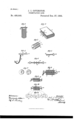
- FIG. l represents a book with my invention applied thereto.
- Fig. 2 is a perspective view of a book constructed to permit the application of the locking means thereto.
- Fig. 3 is a perspective view of the lock.
- Figs. 4 and 5 represent the two parts of the key used in connection with the lock and the means secured to the book.
- Fig. G represents the position of the two parts of the key after insertion in the lock.
- Fig. 7 represents the two constructions of wheels or disks used in the lock.
- Fig. 8 is a longitudinal cross-section of the lock, when locked with key in place.
- Fig. 9 represents a modiiied construction in which all of the wheels are alike in construction.
- Fig. l0 represents the modified construction in locked condition.
- Fig. l1 shows the varying positions of the several wheels of Fig. 10.
- Figs. 1 and 2 has each of its two covers provided with a key hole 2 protected by a metal reinforcing piece 3 irrnly rivet-ed to each cover. These key holes are preferably located where most effective in locking the covers of the book together.
- the lock which I have invented to use in connection with books so constructed consists of a series of disks or wheels 4 and 5 inclosed in a cylindrical case 6 provided with a slot 7 in its side to expose to view the numbers. or characters on the wheels and with a slot 8 in each end corresponding in form to a cross-section of the key.
- the length of the cylinder will vary according to the number of wheels contained therein, the greater the number of wheels the more difficult or impossible of course to open the lock.
- Figs. 3 and 8 I have shown seven wheels consisting of four wheels 5 provided with slots 9 and three wheels 4 having circular opening 10. These two sets of wheels are arranged alternately as shown, the wheels 5 being at the ends of the series.
- Each of the seven wheels has printed or impressed on its periphery (see Fig. 7) a series of numbers from O to 9 arranged consecutively. Instead of numbers, letters or other characters could be used, but numbers are preferred, and instead of using ten numbers on the periphery a less or greater number could be employed.
- each wheel 5 can occupy but two positions that will permitinsertion or removal of key, one being diametrically opposite the other, consequently each lock can be locked or opened on only two different combinations determined at the time of construction of the lock.
- the wheels 4 having each a circular opening sufficiently large to permit revolution of same on the key without the movement of one affecting that of the others, are, therefore, only dummies, and their relative position can be disregarded in using the lock.
- the two' part key cannot therefore be withdrawn until the four wheels are again turned to bring the combination 2469 into view and as the heads 23 of the key cannot pass through the key holes of the covers of the book itfollows that the book cannot be opened.
- the wheels 14 within the cyl inder are all alike, each having formed in it the slot 15.
- the two part key 16 and 17 used in this case has only one projection to each' part, and when the wheels have all their slots in register it is inserted so that the two.projec,
- the four intermediate Wheels can then be turned on the shank of thekey to disarrange the combination as illustrated in Figs. 10 and 1l.
- the key canbe formed like an ordinary key as shown in Figs. 4 and 5 or it may have a fiat milled head as illustrated in Figs. 9 and,10, a retaining head or enlargement being necessary to eReet the locking, said head being so located as to leave a space between the same and the end of the case, or nearest wheel, sufficient, for example, to accommodate the cover of abook.
- a lock consisting of aseries of numbered wheels provided with openings, and a two part key, each part of which is provided with a retaining head and is adapted to pass into the openings in said wheels, said retaining head being so located as to leave a space between it and the nearest wheel when the key is inserted, substantially as described.
- a lock consisting of a series of numbered 7 wheels provided with openings, and a two part key provided with projections, eachv part of said key having a retaining head and adapted to enter into the openings insaid wheels, said retaining head being so locatedas to leave a space between it'and the nearest wheel when the key is inserted, substantially as described.
- a lock consisting of a case provided with slots or key holes in its ends, a series of numbered wheels provided with openings, and a headed key adapted to be passed through the Islots of the case into said wheels, the heads of said key beingso located as to leave a space between the same and the ends of the case when the key is inserted, substantially as de- I scribed.
- a lock consistingof acase provided with slots or key holes in its ends, two sets of numbered wheels of l which one set. is provided with slots and the other set with circular openings, and a headed key adapted to lbe passed through the slots ofthe case into said wheels, the lheads of said key beingso located as to leave a space between the saine and the ends of the case when the key is inserted, substantially as described.
- a lock consisting of y.a ycase yprovided'with slots or key holes in its ends, as eries of numbered Wheels provided with openings, and a two. part'headed key Vprovided. withv projections and adapted toV be passed through the slots of the case into said wheels, the heads of said key being so located as to leave a space between the same and the ends ofthe case when the key is inserted, substantially as described.
Description
' (No M8881.)
, J. I.V COVINGTON.
PBRMUTATION LOCK E15 @www U5 UNTTED STATES PATENT OFFTCE.
JOHN I. COVINGTON, OF BROOKLYN, NEW YORK.
PERMuTATlON-LOOK.
SPECIFICATION forming part of Letters Patent No. 488,648, dated December 2'?, 1892.
Application filed January 9, 1892. Serial No. 417,478. (No model.)
To all whom it may concern..-
Beit known that I, JOHN I. Cov1NGToN,.a citizen of the United States, and a resident of Brooklyn, in the county of Kings and State of New York, have invented certain new and useful Improvements in PermntatiOn-Locks, of which the following is a specification.
My invention relates to permutation locks.
The object of my invention is to construct a cheap, eective and detachable permutation lock which can be readily applied to the thing to be locked and as readily removed therefrom, and I accomplish this object by the means hereinafter described and claimed.
In the accompanying drawingsforming part of this specification Figure l represents a book with my invention applied thereto. Fig. 2 is a perspective view of a book constructed to permit the application of the locking means thereto. Fig. 3 is a perspective view of the lock. Figs. 4 and 5 represent the two parts of the key used in connection with the lock and the means secured to the book. Fig. G represents the position of the two parts of the key after insertion in the lock. Fig. 7 represents the two constructions of wheels or disks used in the lock. Fig. 8 is a longitudinal cross-section of the lock, when locked with key in place. Fig. 9 represents a modiiied construction in which all of the wheels are alike in construction. Fig. l0 represents the modified construction in locked condition. Fig. l1 shows the varying positions of the several wheels of Fig. 10.
The lock hereinafter particularly described I have illustrated as applicable tothe locking of books, but I do not, of course, limit myself to this use of the lock as it is applicable to various other objects and things.
Referring to the drawings the book, Figs. 1 and 2 has each of its two covers provided with a key hole 2 protected by a metal reinforcing piece 3 irrnly rivet-ed to each cover. These key holes are preferably located where most effective in locking the covers of the book together. The lock which I have invented to use in connection with books so constructed consists of a series of disks or wheels 4 and 5 inclosed in a cylindrical case 6 provided with a slot 7 in its side to expose to view the numbers. or characters on the wheels and with a slot 8 in each end corresponding in form to a cross-section of the key. The length of the cylinder will vary according to the number of wheels contained therein, the greater the number of wheels the more difficult or impossible of course to open the lock. In Figs. 3 and 8 I have shown seven wheels consisting of four wheels 5 provided with slots 9 and three wheels 4 having circular opening 10. These two sets of wheels are arranged alternately as shown, the wheels 5 being at the ends of the series. Each of the seven wheels has printed or impressed on its periphery (see Fig. 7) a series of numbers from O to 9 arranged consecutively. Instead of numbers, letters or other characters could be used, but numbers are preferred, and instead of using ten numbers on the periphery a less or greater number could be employed.
I employ in connection with the lock so far described a two part device which is herein for convenience called a key, it forming a member of the lockingrmeans and consisting of the parts ll and 12, each part, if the lock embraces only three wheels as 4, being provided with three projections 13, the number of projections always corresponding to the number of wheels 4. The slots in the wheels 5 are stamped out to occupy a relative, position to the position of the numbers arranged on the periphery, so that when the proper combinations is shown through the opening in the cylinder the slots 9 of all the wheels 5 may be in line with each other and with the slots 8 in the cylinder so that the key may be inserted or withdrawn therefrom. It follows from this construction that each wheel 5 can occupy but two positions that will permitinsertion or removal of key, one being diametrically opposite the other, consequently each lock can be locked or opened on only two different combinations determined at the time of construction of the lock. The wheels 4 having each a circular opening sufficiently large to permit revolution of same on the key without the movement of one affecting that of the others, are, therefore, only dummies, and their relative position can be disregarded in using the lock.
The operation of the mechanism so far described is as follows: If, for example, the lock is constructed to open onv the combination 2469 then the four wheels 5 are turned until IOO these numbers appear opposite theslot in the cylinder. The said cylinder is then applied to the book or other thing to be locked, and the two part key is inserted through the key holes of the covers, in case of a book, into thev cylinder until it occupies the position shown `in Fig. 8 t. e. until the projections of the key are within the circular openings of the wheels 4 after which the wheels 5 are each turned more or less as may be desired to bring their slots 9 out of line with each other and with the slots in the cylinder. The two' part key cannot therefore be withdrawn until the four wheels are again turned to bring the combination 2469 into view and as the heads 23 of the key cannot pass through the key holes of the covers of the book itfollows that the book cannot be opened. In the construction shown in Figs. 9 to 11 the wheels 14 within the cyl inder are all alike, each having formed in it the slot 15. The two part key 16 and 17 used in this case has only one projection to each' part, and when the wheels have all their slots in register it is inserted so that the two.projec,
tions of thekey rest in the first andlastwheels,
in the cylinder. The four intermediate Wheels can then be turned on the shank of thekey to disarrange the combination as illustrated in Figs. 10 and 1l. The key canbe formed like an ordinary key as shown in Figs. 4 and 5 or it may have a fiat milled head as illustrated in Figs. 9 and,10, a retaining head or enlargement being necessary to eReet the locking, said head being so located as to leave a space between the same and the end of the case, or nearest wheel, sufficient, for example, to accommodate the cover of abook.
It is frequently desirable'in addition tol locking a book or other object to prevent its be-` ing stolen or displaced and to this end Ivhave constructed the key so as to not only permit the connection of a chain thereto, butso that the lock will co-operate therewith in prevent-` ing the removal of the chain. Isplit'the shank of the key so as to open the loop 2O of the handle as shown in Fig.` 4 the two separated parts 18and 19 being capable of beingpressed apart to allow a chain 21 to pass through into the loop, and in their closed condition fitting into the slot in the cylinder and thus closing the entrance to the loop 2O and preventing the withdrawal of the chain. The chain thus secured to the book may be fastened to a desk,l stand or othersuitable supportbya staple 22 as shown in Fig. 4, or in any other suitable manner. y y
I do not in this application claim the combination with a book of av separate ,locking means, as I have claimed such combination in an application tiled October 7,1891, Serial No. 407,974.
Having thus described my invention what I claim and desire to secure by United States Letters Patent is,
1. A lock consisting of aseries of numbered wheels provided with openings, and a two part key, each part of which is provided with a retaining head and is adapted to pass into the openings in said wheels, said retaining head being so located as to leave a space between it and the nearest wheel when the key is inserted, substantially as described.
2. A lock consisting of a series of numbered 7 wheels provided with openings, and a two part key provided with projections, eachv part of said key having a retaining head and adapted to enter into the openings insaid wheels, said retaining head being so locatedas to leave a space between it'and the nearest wheel when the key is inserted, substantially as described. 3. A lock consisting of a case provided with slots or key holes in its ends, a series of numbered wheels provided with openings, and a headed key adapted to be passed through the Islots of the case into said wheels, the heads of said key beingso located as to leave a space between the same and the ends of the case when the key is inserted, substantially as de- I scribed.
4. A lock consistingof acase provided with slots or key holes in its ends, two sets of numbered wheels of l which one set. is provided with slots and the other set with circular openings, and a headed key adapted to lbe passed through the slots ofthe case into said wheels, the lheads of said key beingso located as to leave a space between the saine and the ends of the case when the key is inserted, substantially as described.
, 5. A lock consisting of y.a ycase yprovided'with slots or key holes in its ends, as eries of numbered Wheels provided with openings, and a two. part'headed key Vprovided. withv projections and adapted toV be passed through the slots of the case into said wheels, the heads of said key being so located as to leave a space between the same and the ends ofthe case when the key is inserted, substantially as described. y
. 6. A lock in combination with a key having a split shank forming an/open looped handle,
the said shank passing into the lock closing the opening to the loop, substantially as described. l
Signed at New York, in the county of New York and State of New York, this 7th dayof January, A. D. 1892.
Jol-IN i. COVINGTON.
Witnesses: p
C HAs. L. WISE, RUDOLPH H. REDDIsH.
IIO
Publications (1)
| Publication Number | Publication Date |
|---|---|
| US488648A true US488648A (en) | 1892-12-27 |
Family
ID=2557494
Family Applications (1)
| Application Number | Title | Priority Date | Filing Date |
|---|---|---|---|
| US488648D Expired - Lifetime US488648A (en) | John i |
Country Status (1)
| Country | Link |
|---|---|
| US (1) | US488648A (en) |
Cited By (4)
| Publication number | Priority date | Publication date | Assignee | Title |
|---|---|---|---|---|
| US4308730A (en) * | 1980-03-17 | 1982-01-05 | Roth Donald P | Electrical plug locking device |
| US5749251A (en) * | 1995-01-31 | 1998-05-12 | Keefe; Jerome F. | Locking device and ski security system |
| US6305199B1 (en) * | 1994-04-12 | 2001-10-23 | Darrell A. Igelmund | Computer slot security adaptor |
| US6851285B1 (en) * | 2003-09-29 | 2005-02-08 | David J. Haas | Keyless locking device |
-
0
- US US488648D patent/US488648A/en not_active Expired - Lifetime
Cited By (4)
| Publication number | Priority date | Publication date | Assignee | Title |
|---|---|---|---|---|
| US4308730A (en) * | 1980-03-17 | 1982-01-05 | Roth Donald P | Electrical plug locking device |
| US6305199B1 (en) * | 1994-04-12 | 2001-10-23 | Darrell A. Igelmund | Computer slot security adaptor |
| US5749251A (en) * | 1995-01-31 | 1998-05-12 | Keefe; Jerome F. | Locking device and ski security system |
| US6851285B1 (en) * | 2003-09-29 | 2005-02-08 | David J. Haas | Keyless locking device |
Similar Documents
| Publication | Publication Date | Title |
|---|---|---|
| US924331A (en) | Lock. | |
| US488648A (en) | John i | |
| US3514981A (en) | Lock box | |
| US468512A (en) | Means for locking books | |
| US1195808A (en) | Mato gbgich | |
| US376453A (en) | Register key-ring | |
| US6997480B2 (en) | Cord lock device for books and the like | |
| US1463230A (en) | Push-key combination padlock | |
| JP4543280B2 (en) | seal | |
| US1103015A (en) | Lock for mail-bags. | |
| US2985005A (en) | Combination lock | |
| US1017313A (en) | Permutation-lock. | |
| US1253169A (en) | Lock. | |
| US1112706A (en) | Lock. | |
| US438353A (en) | Combination-lock | |
| US1186912A (en) | Book-lock. | |
| US1297025A (en) | Locking mechanism for pocket savings-banks. | |
| US1208194A (en) | Key-actuated mechanism. | |
| US213798A (en) | Improvement in padlocks | |
| US518211A (en) | Charles t | |
| US1291228A (en) | Lock. | |
| US1015908A (en) | Lock for mail-bags and the like. | |
| US766678A (en) | Locking device for umbrellas. | |
| US2635449A (en) | Combination lock | |
| US924321A (en) | Keyhole-guard. |