US4888845A - Sweeping apparatus for railway ballast regulators - Google Patents
Sweeping apparatus for railway ballast regulators Download PDFInfo
- Publication number
- US4888845A US4888845A US07/182,140 US18214088A US4888845A US 4888845 A US4888845 A US 4888845A US 18214088 A US18214088 A US 18214088A US 4888845 A US4888845 A US 4888845A
- Authority
- US
- United States
- Prior art keywords
- broom
- elements
- reel
- railway
- holder
- Prior art date
- Legal status (The legal status is an assumption and is not a legal conclusion. Google has not performed a legal analysis and makes no representation as to the accuracy of the status listed.)
- Expired - Fee Related
Links
Images
Classifications
-
- A—HUMAN NECESSITIES
- A46—BRUSHWARE
- A46B—BRUSHES
- A46B3/00—Brushes characterised by the way in which the bristles are fixed or joined in or on the brush body or carrier
- A46B3/16—Brushes characterised by the way in which the bristles are fixed or joined in or on the brush body or carrier by wires or other anchoring means, specially for U-shaped bristle tufts
-
- A—HUMAN NECESSITIES
- A46—BRUSHWARE
- A46B—BRUSHES
- A46B3/00—Brushes characterised by the way in which the bristles are fixed or joined in or on the brush body or carrier
- A46B3/08—Brushes characterised by the way in which the bristles are fixed or joined in or on the brush body or carrier by clamping
- A46B3/10—Brushes characterised by the way in which the bristles are fixed or joined in or on the brush body or carrier by clamping into rings or the like
- A46B3/14—Brushes characterised by the way in which the bristles are fixed or joined in or on the brush body or carrier by clamping into rings or the like specially adapted for street-cleaning or rail-cleaning brooms
-
- E—FIXED CONSTRUCTIONS
- E01—CONSTRUCTION OF ROADS, RAILWAYS, OR BRIDGES
- E01B—PERMANENT WAY; PERMANENT-WAY TOOLS; MACHINES FOR MAKING RAILWAYS OF ALL KINDS
- E01B27/00—Placing, renewing, working, cleaning, or taking-up the ballast, with or without concurrent work on the track; Devices therefor; Packing sleepers
- E01B27/02—Placing the ballast; Making ballastway; Redistributing ballasting material; Machines or devices therefor; Levelling means
- E01B27/023—Spreading, levelling or redistributing ballast already placed
- E01B27/026—Spreading, levelling or redistributing ballast already placed by means of driven tools, e.g. rotating brooms or digging devices
Definitions
- the present invention relates to sweeper units and, in particular, broom elements and their mounting means used on railway ballast regulators.
- Ballast regulators are employed to perform such functions as plowing and sweeping the gravel (or "ballast") surrounding and supporting railway tracks and ties.
- the broom elements presently utilized take one of three basic forms: solid cylindrical rods, solid squared isosceles trapezoid or solid horseshoe shape rods and a hollow tube or plugged hollow tubes. All of these elements have been constructed of various compounds and combinations of materials in an effort of improving element life and sweeping action.
- the hollow tube form has been the most popular due to the ability to substitute readily available used train brake hoses for the hollow tubes.
- the solid form of broom elements are more durable and perform superior sweeping function over the ballast surface.
- the construction of the holders for these elements has been such that the one side of the holder receiving the side of the broom elements upon impact is contoured but the other side of the holder (i.e. the side which receives the rebounding broom element) is a straight, non-contoured edge.
- these holders tend to prematurely damage broom elements by unduly stressing the broom elements at the impact point between the broom element and the holder upon rebound.
- Tightly clamped broom elements also present another problem of high stress in the broom element at the point where the clamp holding the broom element terminates.
- the repeated flexure of the broom element at the clamping point actually heats the broom element and very often the broom element will fail at that point before the end of the broom element has worn to the point of requiring replacement.
- a problem present with all of the aforementioned designs is that the broom elements located over the tracks, which are some 7 inchs higher than the rest of the surface being swept, tend to receive extreme punishment and deteriorate much faster than the other broom elements.
- hollow tube broom elements used with stepped nipple holders tend to be more forgiving under the stresses caused by the closer sweeping surface of the rails, the combination of the hollow tubes and the stepped nipple elements do not sweep as well or last as long as is desired with respect to the sweeping of the ballast surface.
- the present invention addresses improvements in the design, orientation and means for attaching broom elements to sweeper units of railway ballast regulators.
- the present invention employs solid cylindrical tubes as broom elements which have two opposite sides extruded to create flat striking and rebound surfaces.
- the broom elements are loosely attached to the broom reel of the sweeper unit by means of a novel broom element holder which employs a bolt or pin and cotter pin arrangement.
- This design drastically reduces when in the secured end of the broom element and simplifies the maintenance and replacement of broom elements.
- the broom element holder has contoured lateral sides which limits the stresses which can be caused by the broom element striking the sides of the broom element holder during the flex and rebound of sweeping. This significantly reduces wear on the broom elements.
- Arranging the solid broom element holders in a helical fashion around the broom reel of the sweeper unit eliminates the vibration and noise caused by all the broom elements in a row striking the ballast simultaneously. Instead, an approximately equal number of broom elements will remain in contact with the ballast at all times.
- Creating a hybrid design by arranging stepped nipple broom element holders adapted to receive hollow tube broom elements over the train rails reduces the wear and improves sweeping over the rail area.
- the present invention improves the sweeping action of the sweeping unit while reducing wear on the broom elements and the sweeper unit. Moreover, the present invention significantly reduces the time and effort which must be exerted in order to maintain the sweeper unit of a ballast regulator.
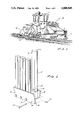
- FIG. 1 is a perspective view of a ballast regulator showing the positioning of a sweeper unit
- FIG. 2 is a three-quarter view of a four-element broom element holder of the present invention, the first broom element and its attachment means shown in exploded orientation;
- FIG. 3 is a broom reel embodying the present invention and shown as if the reel has been cut parallel to its axis and the circumference of the cylinder laid flat;
- FIG. 4 is a cross-sectional view of the broom reel of the present invention showing the orientation of five of the broom element holders around the circumference of the broom reel.
- ballast regulator 10 of known construction incorporating a plow unit 11 on one end and a sweeper unit 12 on the other end.
- the sweeper unit 12 is used to sweep the gravel and other material forming and covering the ballast for the railway track to a uniform height and consistency.
- a motor driven broom reel 13 Attached, such as by welding, to the broom reel 13 are a plurality of broom element holders 14 which each removably provide attachment for one or more broom elements 15.
- the present invention employs two forms of broom elements 15 and two forms of corresponding broom elements holders 14 and 14a.
- the primary broom elements 15 of the present invention are of a unique construction.
- Each primary broom element 15 comprises a cylindrical rod of hard rubber, such as two-inch diameter KLEENSWEEP solid round regulator tube available from T. C. Johnson Company of Chargin Falls, Ohio, which has been extruded on two opposite sides to provide two opposite flat faces 16, 16 of the broom element 15 running parallel to the axis of the broom element 15 for its entire length.
- the primary broom element holders 14 corresponding to the primary broom elements 15 are also of a unique construction.
- Each primary holder 14 contains two lateral sides 18, 18 which are each curved, or “contoured,” away from the interior of the primary holder 14.
- Each primary holder 14 contains three or four seats 17 each adapted to receive a base 19 of one of the primary broom elements 15.
- Each seat 17 has an aperture 20, 20 drilled in each of the lateral sides 18 of the primary holder 14 approximately one inch above the bottom 21 of the primary holder 14 and directly across from one another.
- the thickness of the broom elements 15 between the two opposite flat faces 16, 16 is slightly less than the distance between the two lateral sides 18, 18 of the primary holders 14. This difference in dimensions may be up to as much as 5/8 of an inch. This dimensional difference provides ease of insertion of the broom elements into the holders and also relieves stress as hereinafter discussed.
- each primary broom element has a hole 22 drilled through it between its two extruded faces 16 approximately one inch above its base 19 and corresponding with the apertures 20 in each of the lateral sides 18 of each seat 17 of the primary holder 14.
- a bolt or smooth pin 23 is provided for each primary broom element 15 adapted to pass through the apertures 20, 20 and the hole 22 in the broom element 15.
- the bolt or pin 23 is adapted to be fastened by a cotter pin 24 at the end of the bolt 23 exiting the primary holder 14.
- the primary broom elements 15 are securely but loosely fastened to the broom reel 13 without complicated and burdensome compression-type element holders which are difficult to manipulate.
- the nature of cotter pin attachment greatly eases removal of worn primary broom elements 15 and is not prone to becoming fixed or "frozen” due to adverse environmental conditions.
- this loose securing arrangment permits the secured end of the broom element to move relatively freely within the holder 14 and its seat 17. In this manner, the stress heretofore experienced in clamped broom elements is greatly reduced and the life of the broom element in this region extended up to four times that heretofore experienced.
- the flat faces 16 of the broom elements working in conjunction with the flat surfaces of the lateral sides 18 of the holder 14 absorb and transfer the energy of impact during sweeping and further reduce wear of the broom elements 15.
- the pin and cotter pin arrangement and the associated apertures in the holder and broom element are transverse to the broom reel axis. This is necessitated by the plural seat aspect of the holders. However, in the case where single seat holders may be used, the pin and apertures could be positioned parallel to the broom reel axis.
- the dual curve design of the lateral sides 18, 18 is also provided to further reduce the wear caused to the primary broom element 15 when it strikes the ballast and is flexed against a lateral side 18 of the primary holder 14 and when it rebounds back into the opposite lateral side 18 of the primary holder 14 upon leaving the ballast.
- contouring the holder 14 to receive the broom element 15 during the flex of impact against the ballast is known in the art, the inventors have found that substantial damage is also incurred upon rebound after the broom element 15 has left the ballast. Accordingly, the operational life of the primary broom elements can be significantly extended by contouring both lateral sides 18 of the holder 14.
- the use of the cotter pin-type attachment need not have a straight lateral side in order properly to receive and hold the broom element and thus is capable of employing he dual curve design herein discussed.
- the secondary broom elements (not shown) and their corresponding secondary broom element holder 14a are of known construction. It has been found that hollow tube broom elements and their corresponding stepped nipple holders 14a function very adequately when sweeping the area over the train rails. Accordingly, as seen in FIG. 3, the broom reel 13 is designed to have the stepped nipple holders 14a, 14a, arranged over the train rails so that hollow tube broom elements can be used to sweep the rails. These may be cut shorter than the primary broom elements 15 so to accommodate the higher sweeping surface of the rails. Hard rubber hollow regulator tubes, such as the approximately 2.25 inch outside diameter KLEENSWEEP hollow regulator tube available from T. C.
- the broom element holders 14, 14a are not arranged in straight rows parallel with the axis of the broom reel 13.
- the primary holders 14 are aligned on rows of an approximately three (3) degree spiral or helix around the broom reel 13.
- the secondary holders 14a over the rails are randomly staggered. In this manner, an approximately equal number of solid broom elements 15 will be contacting the ballast at an given time. This avoids the vibration and noise that occurs with the broom reels presently utilized which have the solid broom elements all aligned in straight rows and which thus have an entire row of broom elements strike the ballast surface simultaneously.
Abstract
Description
Claims (7)
Priority Applications (1)
| Application Number | Priority Date | Filing Date | Title |
|---|---|---|---|
| US07/182,140 US4888845A (en) | 1985-09-13 | 1988-04-15 | Sweeping apparatus for railway ballast regulators |
Applications Claiming Priority (2)
| Application Number | Priority Date | Filing Date | Title |
|---|---|---|---|
| US77584885A | 1985-09-13 | 1985-09-13 | |
| US07/182,140 US4888845A (en) | 1985-09-13 | 1988-04-15 | Sweeping apparatus for railway ballast regulators |
Related Parent Applications (1)
| Application Number | Title | Priority Date | Filing Date |
|---|---|---|---|
| US77584885A Continuation-In-Part | 1985-09-13 | 1985-09-13 |
Publications (1)
| Publication Number | Publication Date |
|---|---|
| US4888845A true US4888845A (en) | 1989-12-26 |
Family
ID=26877820
Family Applications (1)
| Application Number | Title | Priority Date | Filing Date |
|---|---|---|---|
| US07/182,140 Expired - Fee Related US4888845A (en) | 1985-09-13 | 1988-04-15 | Sweeping apparatus for railway ballast regulators |
Country Status (1)
| Country | Link |
|---|---|
| US (1) | US4888845A (en) |
Cited By (8)
| Publication number | Priority date | Publication date | Assignee | Title |
|---|---|---|---|---|
| US5022408A (en) * | 1990-04-23 | 1991-06-11 | Mohajer Reza S | Combination exo/endocervical sampler |
| EP0454894A1 (en) * | 1990-05-04 | 1991-11-06 | Prinoth S.P.A. | Securing element for the brush of a cleaning machine |
| US5247717A (en) * | 1989-10-23 | 1993-09-28 | Owen Smith | Debris/litter collecting apparatus |
| US5279307A (en) * | 1992-10-19 | 1994-01-18 | Mohajer Reza S | Combination exo-endocervical sampler |
| US5480099A (en) * | 1994-06-27 | 1996-01-02 | March-Southwestern Corp. | Mill sweep for pulverizers |
| WO2001011145A1 (en) * | 1999-08-09 | 2001-02-15 | Maschinen & Anlagen Service Gmbh | Shaft with brush for cleaning railway lines |
| US20050132514A1 (en) * | 2003-12-23 | 2005-06-23 | St. Godard Donald J.M. | Machine for clearing railroad flangeways |
| US8438711B1 (en) | 2010-03-03 | 2013-05-14 | Norfolk Southern Corporation | Tool and method for removing sweeper bristles from a railway track broom |
Citations (6)
| Publication number | Priority date | Publication date | Assignee | Title |
|---|---|---|---|---|
| US420640A (en) * | 1890-02-04 | Railway-track cleaner | ||
| DE864087C (en) * | 1951-06-20 | 1953-01-22 | Georg Schoenfeld | Wire brush for cleaning machines |
| US3137018A (en) * | 1962-05-29 | 1964-06-16 | Nordberg Manufacturing Co | Brushes for track and right of way |
| US4077081A (en) * | 1976-10-19 | 1978-03-07 | Drumm Arthur E | Sweeper brush section |
| US4484373A (en) * | 1983-03-29 | 1984-11-27 | Price John G | Sweeper bristle element |
| US4707875A (en) * | 1984-08-06 | 1987-11-24 | Famag Fahrzeug- Und Maschinenhandelsgesellschaft M.B.H. Nfg. Kg. | Holding member for working elements of roller brushes |
-
1988
- 1988-04-15 US US07/182,140 patent/US4888845A/en not_active Expired - Fee Related
Patent Citations (6)
| Publication number | Priority date | Publication date | Assignee | Title |
|---|---|---|---|---|
| US420640A (en) * | 1890-02-04 | Railway-track cleaner | ||
| DE864087C (en) * | 1951-06-20 | 1953-01-22 | Georg Schoenfeld | Wire brush for cleaning machines |
| US3137018A (en) * | 1962-05-29 | 1964-06-16 | Nordberg Manufacturing Co | Brushes for track and right of way |
| US4077081A (en) * | 1976-10-19 | 1978-03-07 | Drumm Arthur E | Sweeper brush section |
| US4484373A (en) * | 1983-03-29 | 1984-11-27 | Price John G | Sweeper bristle element |
| US4707875A (en) * | 1984-08-06 | 1987-11-24 | Famag Fahrzeug- Und Maschinenhandelsgesellschaft M.B.H. Nfg. Kg. | Holding member for working elements of roller brushes |
Cited By (12)
| Publication number | Priority date | Publication date | Assignee | Title |
|---|---|---|---|---|
| US5247717A (en) * | 1989-10-23 | 1993-09-28 | Owen Smith | Debris/litter collecting apparatus |
| US5329661A (en) * | 1989-10-23 | 1994-07-19 | Owen Smith | Debris/litter collection apparatus having a conveyor which intermeshes with fingers of collector roller |
| US5022408A (en) * | 1990-04-23 | 1991-06-11 | Mohajer Reza S | Combination exo/endocervical sampler |
| WO1991016004A1 (en) * | 1990-04-23 | 1991-10-31 | Mohajer Reza S | Combination exo/endocervical sampler |
| EP0454894A1 (en) * | 1990-05-04 | 1991-11-06 | Prinoth S.P.A. | Securing element for the brush of a cleaning machine |
| US5279307A (en) * | 1992-10-19 | 1994-01-18 | Mohajer Reza S | Combination exo-endocervical sampler |
| US5480099A (en) * | 1994-06-27 | 1996-01-02 | March-Southwestern Corp. | Mill sweep for pulverizers |
| WO2001011145A1 (en) * | 1999-08-09 | 2001-02-15 | Maschinen & Anlagen Service Gmbh | Shaft with brush for cleaning railway lines |
| US20050132514A1 (en) * | 2003-12-23 | 2005-06-23 | St. Godard Donald J.M. | Machine for clearing railroad flangeways |
| US20070039514A1 (en) * | 2003-12-23 | 2007-02-22 | Godard Donald J M | Machine for clearing railroad flangeways |
| US8438711B1 (en) | 2010-03-03 | 2013-05-14 | Norfolk Southern Corporation | Tool and method for removing sweeper bristles from a railway track broom |
| US9364928B2 (en) | 2010-03-03 | 2016-06-14 | Norfolk Southern Corporation | Tool and method for removing sweeper bristles from a railway track broom |
Similar Documents
| Publication | Publication Date | Title |
|---|---|---|
| US4888845A (en) | Sweeping apparatus for railway ballast regulators | |
| KR101203086B1 (en) | Toothbrush | |
| US5222588A (en) | Secondary conveyor belt cleaners | |
| US4587686A (en) | Windshield wiper | |
| KR880002460B1 (en) | Conveyor belt cleaner | |
| AU761452B2 (en) | Differential wear conveyor belt scraper blade | |
| AU660139B2 (en) | Conveyor belt cleaners | |
| US7178418B2 (en) | Segment of a sensor-supporting element for a scraper-type device | |
| SK4712002A3 (en) | Toothbrush having a bristle pattern providing enhanced cleaning | |
| CN103068336B (en) | Fracture resistant brush head | |
| US6014789A (en) | Multiple tube cleaning pig featuring replaceable disks anchoring cleaning studs | |
| US5238055A (en) | Field adjustable rapper tie bar | |
| CA2436839A1 (en) | Toothbrush with longitudinal bristle reinforcement | |
| US5315966A (en) | Hammering device for tube boilers | |
| US20120305367A1 (en) | Arrangement for stripping material from the lower run of the conveyor belt of a belt conveyor | |
| US4319378A (en) | Chimney cleaner | |
| US6401803B1 (en) | Stake for tube bundle | |
| US4480350A (en) | Sweeper bristle | |
| US4184223A (en) | Sweeper bristle element | |
| US4285737A (en) | Method of cleaning railroad track | |
| US4484373A (en) | Sweeper bristle element | |
| US4707875A (en) | Holding member for working elements of roller brushes | |
| US1168849A (en) | Rotary broom. | |
| US2056058A (en) | Brush mat | |
| EP0497324B1 (en) | Conveyor belt cleaners |
Legal Events
| Date | Code | Title | Description |
|---|---|---|---|
| AS | Assignment |
Owner name: RAILWAY TRACK-WORK COMPANY, PENNSYLVANIA Free format text: ASSIGNMENT OF ASSIGNORS INTEREST.;ASSIGNORS:RAMM, EDMUND C.;NOGAN, JOHN J. II;REEL/FRAME:005178/0698 Effective date: 19880422 |
|
| FEPP | Fee payment procedure |
Free format text: PAYOR NUMBER ASSIGNED (ORIGINAL EVENT CODE: ASPN); ENTITY STATUS OF PATENT OWNER: LARGE ENTITY |
|
| FEPP | Fee payment procedure |
Free format text: PAT HLDR NO LONGER CLAIMS SMALL ENT STAT AS INDIV INVENTOR (ORIGINAL EVENT CODE: LSM1); ENTITY STATUS OF PATENT OWNER: LARGE ENTITY |
|
| FPAY | Fee payment |
Year of fee payment: 4 |
|
| FPAY | Fee payment |
Year of fee payment: 8 |
|
| AS | Assignment |
Owner name: HARSCO TECHNOLOGIES CORPORATION, MINNESOTA Free format text: ASSIGNMENT OF ASSIGNORS INTEREST;ASSIGNOR:HARSCO CORPORATION;REEL/FRAME:009197/0680 Effective date: 19980501 |
|
| REMI | Maintenance fee reminder mailed | ||
| LAPS | Lapse for failure to pay maintenance fees | ||
| STCH | Information on status: patent discontinuation |
Free format text: PATENT EXPIRED DUE TO NONPAYMENT OF MAINTENANCE FEES UNDER 37 CFR 1.362 |
|
| FP | Lapsed due to failure to pay maintenance fee |
Effective date: 20011226 |