US4888986A - Rotational position indicator - Google Patents
Rotational position indicator Download PDFInfo
- Publication number
- US4888986A US4888986A US07/322,620 US32262089A US4888986A US 4888986 A US4888986 A US 4888986A US 32262089 A US32262089 A US 32262089A US 4888986 A US4888986 A US 4888986A
- Authority
- US
- United States
- Prior art keywords
- armature
- actuating
- angular
- relative
- position sensors
- Prior art date
- Legal status (The legal status is an assumption and is not a legal conclusion. Google has not performed a legal analysis and makes no representation as to the accuracy of the status listed.)
- Expired - Lifetime
Links
Images


Classifications
-
- H—ELECTRICITY
- H03—ELECTRONIC CIRCUITRY
- H03M—CODING; DECODING; CODE CONVERSION IN GENERAL
- H03M1/00—Analogue/digital conversion; Digital/analogue conversion
- H03M1/12—Analogue/digital converters
- H03M1/22—Analogue/digital converters pattern-reading type
- H03M1/24—Analogue/digital converters pattern-reading type using relatively movable reader and disc or strip
- H03M1/28—Analogue/digital converters pattern-reading type using relatively movable reader and disc or strip with non-weighted coding
-
- G—PHYSICS
- G01—MEASURING; TESTING
- G01D—MEASURING NOT SPECIALLY ADAPTED FOR A SPECIFIC VARIABLE; ARRANGEMENTS FOR MEASURING TWO OR MORE VARIABLES NOT COVERED IN A SINGLE OTHER SUBCLASS; TARIFF METERING APPARATUS; MEASURING OR TESTING NOT OTHERWISE PROVIDED FOR
- G01D5/00—Mechanical means for transferring the output of a sensing member; Means for converting the output of a sensing member to another variable where the form or nature of the sensing member does not constrain the means for converting; Transducers not specially adapted for a specific variable
- G01D5/12—Mechanical means for transferring the output of a sensing member; Means for converting the output of a sensing member to another variable where the form or nature of the sensing member does not constrain the means for converting; Transducers not specially adapted for a specific variable using electric or magnetic means
- G01D5/244—Mechanical means for transferring the output of a sensing member; Means for converting the output of a sensing member to another variable where the form or nature of the sensing member does not constrain the means for converting; Transducers not specially adapted for a specific variable using electric or magnetic means influencing characteristics of pulses or pulse trains; generating pulses or pulse trains
- G01D5/249—Mechanical means for transferring the output of a sensing member; Means for converting the output of a sensing member to another variable where the form or nature of the sensing member does not constrain the means for converting; Transducers not specially adapted for a specific variable using electric or magnetic means influencing characteristics of pulses or pulse trains; generating pulses or pulse trains using pulse code
- G01D5/2492—Pulse stream
-
- G—PHYSICS
- G01—MEASURING; TESTING
- G01P—MEASURING LINEAR OR ANGULAR SPEED, ACCELERATION, DECELERATION, OR SHOCK; INDICATING PRESENCE, ABSENCE, OR DIRECTION, OF MOVEMENT
- G01P13/00—Indicating or recording presence, absence, or direction, of movement
- G01P13/02—Indicating direction only, e.g. by weather vane
Definitions
- This invention relates to a new rotational position indicator useful for example for indicating wind direction or more generally for indicating the rotational position of a shaft. More specifically the invention provides an absolute rotational position indicator that generates 36 unique position codes for identifying successive 10° intervals of absolute angular positioning of a weather vane shaft or other rotating shaft.
- U.S. Pat. No. 4,287,762 describes a digital electronic weather station or weather monitor with digital display and circuitry for selecting and displaying any of a number of monitored weather functions such as indoor and outdoor temperatures, pressure, rainfall, humidity, wind speed and wind direction.
- the weather parameters are monitored by various transducers coupled to the weather center circuitry.
- the transducers generally utilize the rotational motion or other displacement of a respective parameter responsive structure and incorporate visible calibration marks for example in a digital code pattern to be read by a stationary optical reader or photo detector which provides electrical output signals for processing.
- the optical reading techniques used in U.S. Pat. No. 4,287,762 generally transform analog devices typically employing as the moveable analog element a rotatable shaft into digital read out devices and are applicable not only to weather transducers but to condition sensing instruments generally.
- the Schroeder U.S. Pat. No. 4,086,580 describes another relative rotational position shaft encoder or incremental encoder which provides a series of discrete output signals as a function of rotation. Attached to the shaft is a disk with solid portions and slots. A light source and a pair of light detectors generate a first signal related to the amount of rotation and a second signal dependent upon the direction of rotation. The determination of rotational position is dependent upon an original reference position or initial zero position and is subject to cumulative error. Another such incremental optical shaft encoder is described in the Stabler U.S. Pat. No. 2,656,106. A magnetic rotational position sensing apparatus is described in the Sullivan U.S. Pat. No. 3,268,887.
- Another object of the invention is to provide such a simplified absolute rotational position indicator applicable for use with weather vane shafts for generating unique position codes which may be processed by a digital electronic weather center or weather monitor for displaying wind direction.
- the present invention provides a new rotational position indicator with a stator or stationary reference having nine position sensors substantially equally spaced around the circumference of a circle.
- An armature is mounted for rotation on an axis located at the center of the circle.
- the armature is formed with two position sensor actuators mounted at approximately 140° relative to each other.
- Each position sensor actuator is mounted at a radial position for selectively actuating the position sensors upon rotation of the armature.
- An electric circuit is coupled to each position sensor for indicating actuation or not of the respective position sensor providing the unique position codes for successive intervals of angular positioning of the armature relative to the stator.
- the actuators are constructed and arranged to have an actuating effect on the position sensors over a selected angular interval which produces 36 unique position codes for identifying successive 10° intervals of angular positioning of the armature relative to the stator.
- the geometry of the actuator is arranged so that the actuating effect on position sensors extends over an angular interval selected to be at least as great as the angular spacing between two adjacent position sensors.
- a feature and advantage of the present invention is that the novel geometry of the stator or stationary reference of position sensors and the armature assures unique and absolute encoding for each 10° interval of angular positioning around the circle. While the circle may be of varying diameter, the equal spacing between position sensors is an equal spacing of approximately 40°. In the preferred example embodiment the actuators are constructed and arranged to have an actuating effect on position sensors over an angular interval selected to be within a range of at least as great as 40° and less than 60°.
- the magnet geometry is selected to provide fringing magnetic fields having an actuating effect over a selected angular interval within the preferred angular interval range.
- magnetic actuators magnetic read switches or Hall effect switches may be used for the position sensors.
- Optical or electrical sensors and actuators may also be used, arranged according to the geometry of the invention.
- the electrical circuit may include a parallel to serial shift register operatively coupled with nine parallel inputs from the nine position sensors and a data line output for delivering unique position codes in a serial stream of bits.
- the microprocessor of a weather center processes the unique position codes for displaying the angular position for example of a weather vane shaft corresponding to wind direction.
- the position reference sensors may rotate while the actuators in the unique angular relationship according to the invention may be stationary.
- Other arrangements for relative rotation may be used.
- the geometry and actuating range of the actuators may be varied generating other unique position codes for the position intervals.
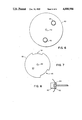
- FIG. 1 is a diagrammatic plan view of the stator or stationary reference and position sensors arranged according to the present invention.
- FIG. 2 is a diagrammatic plan view of the stationary reference and position sensors with an armature mounted for rotation over the position sensors on an axis located at the center of the circle of position sensors.
- FIG. 3 is a diagrammatic side view of a magnetic actuator showing the fringing fields and range of actuating effect.
- FIG. 4 is an enlarged diagrammatic plan view of the circle of position sensors for demonstrating the unique angular interval position encoding achieved by the two actuators at approximately 140° relative to each other according to the selected range of actuating effect of the actuators.
- FIG. 5 is a schematic block diagram of the electrical circuit coupling of the absolute rotational position encoder.
- FIG. 6 is a plan view of a disk configuration armature according to the invention.
- FIG. 7 is a plan view of an optical disk armature for an optical system embodiment according to the invention.
- FIG. 8 is a diagrammatic side view of an optical interrupter position sensor for an optical system embodiment of the invention.
- FIG. 1 The stationary position reference or “stator” for a rotational position indicator according to the present invention is illustrated in FIG. 1.
- a stationary base 12 is provided on which is mounted nine magnetically actuated reed switches 1-9 which function as the position sensors.
- the reed switch position sensors 1-9 are mounted on the base or circuit board 12 equally spaced around the circumference of an imaginary circle 14.
- the reed switches 1-9 are oriented with the elongate dimension of the reed switches in the radial direction equally spaced from the center axis 15 of the imaginary circle 14.
- the base 12 may function as a circuit board or incorporate a printed circuit board with the nine leads from reed switches 1-9 coupled to the parallel inputs of the parallel to serial shift register 16 mounted on the base 12.
- the shift register 16 is in turn coupled through leads l8a-l8e through cable 18 for example to a microprocessor as hereafter described.
- a shaft whose rotational position is to be determined and indicated is positioned at the axis 15 at the center of the imaginary circle 14.
- the moving element, armature or actuator assembly 20 is mounted for rotation on the axis 15 for example as shown in FIG. 2.
- the moving element or armature 20 may be mounted directly on a shaft who's rotational position is to be established or on a rotating axial element coupled to the shaft.
- the rotating armature 20 is constructed with two radial arms 22 and 24 that are fixed relative to each other at an angle of 140°.
- 140° A small variation on either side of 140° of no more than a few degrees may be tolerated according to the other dimensions and parameters of the system as hereafter described but the unique geometry and position coding according to the present invention requires the angular relationship between the radial arms 22 and 24 of approximately 140° and preferably 140°.
- This unique geometrical configuration according to the invention produces a unique position code from the shift register 16 for each 10° interval of rotational position of the moving element or armature 20 relative to the position reference base 12 as hereafter analyzed in further detail.
- a position sensor actuator 25 in this example a button magnet, a magnet in the configuration of a small cylinder approximately 1/2 inch (1.3 cm) in diameter and 1/4 inch (0.6 cm) in thickness.
- Typical dimensions for the rotational position indicator components may be as follows.
- the circuit board base 12 is a disk for example 5 inches (12.7 cm) in diameter.
- the reed switches 1-9 are mounted with the mid points of the elongate dimension of the reed switches lying equally spaced around the circumference of an imaginary circle for example 21/2 inches to 3 inches (6.3-7.6 cm) in diameter. In the illustrated example of a three inch diameter circle, the circumference is approximately 9.4 inches (24 cm).
- the 40° equal angular spacing between the reed switches therefore results in a spacing between mid points of the reed switches at the circumference of approximately 1.05 inches (2.6 cm).
- a magnet actuator of the dimensions illustrated in FIG. 3 is preferred.
- the magnetization of the button magnet is oriented with the north south poles lying along the axis of the small cylinder.
- the fringing fields extending from the magnet actuator result in an effective actuating dimension of approximately 11/4 inches (3.2 cm) in width or diameter with respect to the reed switches mounted on the stationary reference base or stator 12.
- the effective actuating width of the actuator 25 is therefore slightly greater than the circumferential spacing between the reed switch centers.
- each actuator may actuate two adjacent reed switches at a time in some positions, and only one reed switch at a time in other rotational positions. The result is a unique position code for each 10° interval in which either two or three unique combination of reed switches or other position sensors are actuated for each 10° interval.
- the angular dimensions establish the unique geometry according to the invention.
- the nine position sensors should be spaced at approximately 40° intervals around the circumference of the circle of selected dimension.
- the actuating width or diameter of the actuator must be at least as great as the angular spacing of adjacent position sensors that is ⁇ 40°.
- the preferred range of effective actuating width for the actuator is from ⁇ 40° to ⁇ 60°. Within this range the armature will actuate a unique combination of either two or three of the nine lead switches for each 10° interval of the circle as can be verified with reference to the 10° interval compass rose of FIG. 4.
- the code may be determined and verified by placing two circles on the compass rose of FIG. 4, each for example with an angular width or diameter of 50°, at two locations on radial arms fixed at 140° relative to each other. In each instance a unique position code is generated as set forth in Table I. For each 10° angular interval of positioning of the first actuator, Table I indicates which combination of reed switches is actuated along with the corresponding binary "on/off" code that is input in parallel to the shift register and output in serial from the shift register.
- actuators of larger effective actuating angular width or diameter may be used for generating other unique 10° interval codes.
- a unique position code is generated in which either three or four of the nine reed switches or other position sensors are actuated for each 10° interval.
- a unique position code is generated with a unique combination of either 4 or 5 reed switches actuated for each 10° interval rotational position on the circle.
- the preferred range of effective actuator width in angular intervals is >40° and ⁇ 60°.
- a magnet button is described for example in U.S. Pat. No. 4,627,277 for "Magnet Selector or Switch.”
- FIG. 5 A block diagram of the electrical couplings according to the present invention is illustrated in FIG. 5.
- the rotational shaft for example a weather vane shaft 30 places the two actuators of the armature 20 in a specified angular positioning with reference to the nine position sensors 1-9.
- the binary on/off indication of each position sensor provides one input to the nine parallel inputs to shift register 16 which in turn provides a unique position code in the form of a serial stream of bits over data line 18a to the weather station or weather center microprocessor 34.
- the serial stream position code for each interval is specified in the third column of TABLE I. As a result the wind direction is displayed on display 35 in 10° intervals for example in the format set forth in U.S. Pat. No.
- stator and armature may be reversed and that the only requirement is one of relative rotation between the two components of the rotational position indicator.
- position reference or base 12 on which the position sensors are mounted may rotate relative to a stationary actuator 20.
- brushes are required to pick up the leads from the moving element for example a five brush slipring.
- both of the elements may be mounted for rotation relative to each other.
- the electrical circuitry may of course take a variety of forms.
- the shift register may be for example a 4021 (generic number) parallel to serial shift register.
- the clock sampling of the shift register with nine pulses to a cycle may be at desired periodic intervals. For example when wind direction is selected for indication on the microprocessor indicator display, a sampling of the shift register of for example 100 times per second may be used.
- the microprocessor may be programmed with a look up table in which a desired format of wind direction display is correlated with each of the unique position codes.
- a variety of position sensors may also be used. In the case of other magnetic sensors for example Hall effect transducers as described in U.S. Pat. No. 4,667,514 for "Parameter Sensors and Monitors" may be used.
- FIG. 6 Another configuration of the armature according to the invention, a disk, circle or ring, is illustrated in FIG. 6.
- the disk armature 40 is formed with a central axis of rotation 42 and a pair of cups 44 and 45 for retaining the magnets and forming an angle of 140° relative to each other through the axis 42.
- the retaining cups are at radial positions for actuating the position sensors upon rotation of the disk.
- FIG. 7 A rotating armature for an optical system embodiment of the invention is illustrated in FIG. 7.
- the optical disk armature 50 is formed with a center axis of rotation 52 and two open actuator segments 54 and 55 centered at 140° with respect to each other through the center axis.
- the angular width of each open actuator segment 54 and 55 is approximately 50°.
- the position sensors are optical interrupters 60 as illustrated in FIG. 8.
- Each optical interrupter position sensor 60 is formed with a light source 62 such as an LED and a photo sensor 64.
- Light coupling position sensing is enabled by the open actuator segments 54 and 55 of optical disk armature 50.
- Nine optical interrupter position sensors are equally spaced in a circle on a stator or stationary position reference as described above.
Abstract
Description
              TABLE I
______________________________________
10°    Actuated    Unique
Degree        Reed        Serial
Interval      Switches    Position Code
______________________________________
0°/360°
              1,4,5       100110000
 10°   1,5         100010000
 20°   1,2,5       110010000
 30°   2,5         010010000
 40°   2,5,6       010110000
 50°   2,6         010001000
 60°   2,3,6       011001000
 70°   3,6         001001000
 80°   3,6,7       001001100
 90°   3,7         001000100
100°   3,4,7       001100100
110°   4,7         000100100
120°   4,7,8       000100110
130°   4,8         000100010
140°   4,5,8       000110010
150°   5,8         000010010
160°   5,8,9       000010011
170°   5,9         000010001
180°   5,6,9       000011001
190°   6,9         000001001
200°   1,6,9       100001001
210°   1,6         100001000
220°   1,6,7       100001100
230°   1,7         100000100
240°   1,2,7       110000100
250°   2,7         010000100
260°   2,7,8       010000110
270°   2,8         010000010
280°   2,3,8       011000010
290°   3,8         001000010
300°   3,8,9       001000011
310°   3,9         001000001
320°   3,4,9       001100001
330°   4,9         000100001
340°   1,4,9       100100001
350°   1,4         100100000
______________________________________
Claims (20)
Priority Applications (1)
| Application Number | Priority Date | Filing Date | Title |
|---|---|---|---|
| US07/322,620 US4888986A (en) | 1989-03-13 | 1989-03-13 | Rotational position indicator |
Applications Claiming Priority (1)
| Application Number | Priority Date | Filing Date | Title |
|---|---|---|---|
| US07/322,620 US4888986A (en) | 1989-03-13 | 1989-03-13 | Rotational position indicator |
Publications (1)
| Publication Number | Publication Date |
|---|---|
| US4888986A true US4888986A (en) | 1989-12-26 |
Family
ID=23255672
Family Applications (1)
| Application Number | Title | Priority Date | Filing Date |
|---|---|---|---|
| US07/322,620 Expired - Lifetime US4888986A (en) | 1989-03-13 | 1989-03-13 | Rotational position indicator |
Country Status (1)
| Country | Link |
|---|---|
| US (1) | US4888986A (en) |
Cited By (11)
| Publication number | Priority date | Publication date | Assignee | Title |
|---|---|---|---|---|
| US5421198A (en) * | 1993-12-10 | 1995-06-06 | Windrop Weather Devices | Weather monitoring apparatus and method |
| US5760712A (en) * | 1996-09-04 | 1998-06-02 | American Circuit Technology, Inc. | Fuel time indicator |
| US20020196113A1 (en) * | 2001-05-16 | 2002-12-26 | Jeffrey Rudd | Non-contact ignition switch |
| US6670874B1 (en) * | 2002-08-09 | 2003-12-30 | Robert D. Galli | Magnetic rotary switch mechanism |
| US6908310B1 (en) | 2004-03-11 | 2005-06-21 | Deepsea Power & Light | Slip ring assembly with integral position encoder |
| US20050162227A1 (en) * | 2001-12-10 | 2005-07-28 | Robert Galli | Magnetic rotary switch mechanism |
| US20060273899A1 (en) * | 2005-06-03 | 2006-12-07 | Michel Bilodeau | Motion detecting system for alarm device |
| US20070146171A1 (en) * | 2005-12-28 | 2007-06-28 | Kouhei Igarashi | Optical encoder device for small-sized motor and method of producing the same |
| US20070279167A1 (en) * | 2006-06-01 | 2007-12-06 | Elesta Relays Gmbh | Set with a position sensor and an exciter part |
| USRE43903E1 (en) | 1997-02-13 | 2013-01-01 | Richmond Ip Holdings, Llc | Severe weather detector and alarm |
| US20220381801A1 (en) * | 2021-05-27 | 2022-12-01 | Airbus Operations S.A.S. | Device for Measuring the Orientation of a Fluid Flow Relative to an Aerodynamic Surface, in Particular of an Aircraft, Using a Magnetic Sensor |
Citations (16)
| Publication number | Priority date | Publication date | Assignee | Title |
|---|---|---|---|---|
| US2656106A (en) * | 1942-08-10 | 1953-10-20 | Howard P Stabler | Shaft position indicator having reversible counting means |
| US3122735A (en) * | 1960-12-27 | 1964-02-25 | Gen Dynamics Corp | Electronic shaft position indicator having error cancelling means |
| US3123818A (en) * | 1957-01-23 | 1964-03-03 | Bidirectional quantizer | |
| US3268887A (en) * | 1959-11-12 | 1966-08-23 | Electro Mechanical Res Inc | Position sensing apparatus |
| US3364740A (en) * | 1965-03-31 | 1968-01-23 | Lan J. Wong | Wind vane position sensing device |
| US3371336A (en) * | 1964-07-02 | 1968-02-27 | Ibm | Hermetically sealed coded rotary switch |
| US3381288A (en) * | 1962-03-23 | 1968-04-30 | Philips Corp | Apparatus for the remote indication of the position of a rotary shaft |
| US3434136A (en) * | 1965-08-27 | 1969-03-18 | Berkeley Instr | Digital data system |
| US3549897A (en) * | 1968-04-04 | 1970-12-22 | Dynamics Res Corp | Absolute encoder having plurality of binarily related reticle tracks |
| US4041483A (en) * | 1975-04-18 | 1977-08-09 | Rockwell International Corporation | Absolute incremental hybrid shaft position encoder |
| US4086580A (en) * | 1975-12-18 | 1978-04-25 | Schroeder Rondon L | Digital altitude encoder |
| US4287762A (en) * | 1979-08-06 | 1981-09-08 | Rainwise, Inc. | Digital weather station |
| US4422328A (en) * | 1981-10-13 | 1983-12-27 | Sierra Misco | Liquid level sensor |
| US4544913A (en) * | 1983-09-22 | 1985-10-01 | Motorola, Inc. | Fast indexing encoder apparatus |
| US4627277A (en) * | 1985-05-17 | 1986-12-09 | Rainwise, Inc. | Magnet selector or switch |
| US4667514A (en) * | 1985-05-01 | 1987-05-26 | Baer John S | Parameter sensors and monitors |
-
1989
- 1989-03-13 US US07/322,620 patent/US4888986A/en not_active Expired - Lifetime
Patent Citations (16)
| Publication number | Priority date | Publication date | Assignee | Title |
|---|---|---|---|---|
| US2656106A (en) * | 1942-08-10 | 1953-10-20 | Howard P Stabler | Shaft position indicator having reversible counting means |
| US3123818A (en) * | 1957-01-23 | 1964-03-03 | Bidirectional quantizer | |
| US3268887A (en) * | 1959-11-12 | 1966-08-23 | Electro Mechanical Res Inc | Position sensing apparatus |
| US3122735A (en) * | 1960-12-27 | 1964-02-25 | Gen Dynamics Corp | Electronic shaft position indicator having error cancelling means |
| US3381288A (en) * | 1962-03-23 | 1968-04-30 | Philips Corp | Apparatus for the remote indication of the position of a rotary shaft |
| US3371336A (en) * | 1964-07-02 | 1968-02-27 | Ibm | Hermetically sealed coded rotary switch |
| US3364740A (en) * | 1965-03-31 | 1968-01-23 | Lan J. Wong | Wind vane position sensing device |
| US3434136A (en) * | 1965-08-27 | 1969-03-18 | Berkeley Instr | Digital data system |
| US3549897A (en) * | 1968-04-04 | 1970-12-22 | Dynamics Res Corp | Absolute encoder having plurality of binarily related reticle tracks |
| US4041483A (en) * | 1975-04-18 | 1977-08-09 | Rockwell International Corporation | Absolute incremental hybrid shaft position encoder |
| US4086580A (en) * | 1975-12-18 | 1978-04-25 | Schroeder Rondon L | Digital altitude encoder |
| US4287762A (en) * | 1979-08-06 | 1981-09-08 | Rainwise, Inc. | Digital weather station |
| US4422328A (en) * | 1981-10-13 | 1983-12-27 | Sierra Misco | Liquid level sensor |
| US4544913A (en) * | 1983-09-22 | 1985-10-01 | Motorola, Inc. | Fast indexing encoder apparatus |
| US4667514A (en) * | 1985-05-01 | 1987-05-26 | Baer John S | Parameter sensors and monitors |
| US4627277A (en) * | 1985-05-17 | 1986-12-09 | Rainwise, Inc. | Magnet selector or switch |
Cited By (16)
| Publication number | Priority date | Publication date | Assignee | Title |
|---|---|---|---|---|
| US5421198A (en) * | 1993-12-10 | 1995-06-06 | Windrop Weather Devices | Weather monitoring apparatus and method |
| US5760712A (en) * | 1996-09-04 | 1998-06-02 | American Circuit Technology, Inc. | Fuel time indicator |
| USRE45514E1 (en) | 1997-02-13 | 2015-05-12 | La Crosse Technology Ip Holdings, Llc | Severe weather detector and alarm |
| USRE43903E1 (en) | 1997-02-13 | 2013-01-01 | Richmond Ip Holdings, Llc | Severe weather detector and alarm |
| US20020196113A1 (en) * | 2001-05-16 | 2002-12-26 | Jeffrey Rudd | Non-contact ignition switch |
| US20050162227A1 (en) * | 2001-12-10 | 2005-07-28 | Robert Galli | Magnetic rotary switch mechanism |
| US6964510B2 (en) | 2001-12-10 | 2005-11-15 | Robert Galli | Magnetic rotary switch mechanism |
| US6670874B1 (en) * | 2002-08-09 | 2003-12-30 | Robert D. Galli | Magnetic rotary switch mechanism |
| US6908310B1 (en) | 2004-03-11 | 2005-06-21 | Deepsea Power & Light | Slip ring assembly with integral position encoder |
| US7385505B2 (en) * | 2005-06-03 | 2008-06-10 | Michel Bilodeau | Motion detecting system for alarm device |
| US20060273899A1 (en) * | 2005-06-03 | 2006-12-07 | Michel Bilodeau | Motion detecting system for alarm device |
| US20070146171A1 (en) * | 2005-12-28 | 2007-06-28 | Kouhei Igarashi | Optical encoder device for small-sized motor and method of producing the same |
| US7362242B2 (en) * | 2005-12-28 | 2008-04-22 | Mabuchi Motor Co. Ltd. | Optical encoder device for small-sized motor and method of producing the same |
| US7782163B2 (en) * | 2006-06-01 | 2010-08-24 | Pilz Auslandsbeteiligungen Gmbh | Set with a position sensor and an exciter part |
| US20070279167A1 (en) * | 2006-06-01 | 2007-12-06 | Elesta Relays Gmbh | Set with a position sensor and an exciter part |
| US20220381801A1 (en) * | 2021-05-27 | 2022-12-01 | Airbus Operations S.A.S. | Device for Measuring the Orientation of a Fluid Flow Relative to an Aerodynamic Surface, in Particular of an Aircraft, Using a Magnetic Sensor |
Similar Documents
| Publication | Publication Date | Title |
|---|---|---|
| CA2476464C (en) | Methods and apparatus for sensing angular position of a rotatable shaft | |
| JP4733338B2 (en) | Multi-turn code shaft encoder | |
| US5894678A (en) | Electronic linear tape measure using a low power induced current position transducer | |
| US5746005A (en) | Angular position sensor | |
| JP4464637B2 (en) | Multi-turn angle measuring instrument | |
| US5029304A (en) | Sensor with absolute digital output utilizing Hall Effect devices | |
| US6914543B2 (en) | Method for initializing position with an encoder | |
| US4888986A (en) | Rotational position indicator | |
| EP1010967B1 (en) | Encoder for providing incremental and absolute position data | |
| JPH0471444B2 (en) | ||
| JP2002513923A (en) | Multi-turn encoder | |
| US4740690A (en) | Absolute combinational encoders coupled through a fixed gear ratio | |
| US4901072A (en) | Position detector utilizing gray code format | |
| EP3091339B1 (en) | Nonvolatile rotation sensor with spiral track | |
| JP2010044055A (en) | Inductive multiturn encoder | |
| US7406772B2 (en) | Device for measuring the position, the path or the rotational angle of an object | |
| JP2001183173A (en) | Measured value transmitter and method of measuring position of sensor head | |
| CN218847244U (en) | Magneto-optical encoder and electrical equipment | |
| US7119535B2 (en) | Angular displacement encoder with two magnetic tracks | |
| JP4290281B2 (en) | Absolute sensor | |
| CA1225151A (en) | Apparatus for digital angular measurement | |
| EP1016852A1 (en) | Apparatus for measuring the position of a movable member | |
| TWI656326B (en) | Magnetic induction coding device | |
| GB2241125A (en) | Digital shaft-encoder | |
| JP2979692B2 (en) | Magnetic encoder |
Legal Events
| Date | Code | Title | Description |
|---|---|---|---|
| AS | Assignment |
Owner name: RAINWISE, INC., A CORP. OF ME, MAINE Free format text: ASSIGNMENT OF ASSIGNORS INTEREST.;ASSIGNORS:BAER, JOHN S.;VIETTI, MICHAEL A.;REEL/FRAME:005054/0109 Effective date: 19890313 |
|
| FPAY | Fee payment |
Year of fee payment: 4 |
|
| FPAY | Fee payment |
Year of fee payment: 8 |
|
| FEPP | Fee payment procedure |
Free format text: PAYOR NUMBER ASSIGNED (ORIGINAL EVENT CODE: ASPN); ENTITY STATUS OF PATENT OWNER: SMALL ENTITY |
|
| REMI | Maintenance fee reminder mailed | ||
| FPAY | Fee payment |
Year of fee payment: 12 |
|
| SULP | Surcharge for late payment |
Year of fee payment: 11 |
|
| STCF | Information on status: patent grant |
Free format text: PATENTED CASE |
|
| AS | Assignment |
Owner name: NIELSEN-KELLERMAN CO., PENNSYLVANIA Free format text: MERGER;ASSIGNOR:RAINWISE, INC.;REEL/FRAME:057260/0133 Effective date: 20210629 |