US4894664A - Monolithic thermal ink jet printhead with integral nozzle and ink feed - Google Patents
Monolithic thermal ink jet printhead with integral nozzle and ink feed Download PDFInfo
- Publication number
- US4894664A US4894664A US07/125,433 US12543387A US4894664A US 4894664 A US4894664 A US 4894664A US 12543387 A US12543387 A US 12543387A US 4894664 A US4894664 A US 4894664A
- Authority
- US
- United States
- Prior art keywords
- ink
- heater element
- resistive heater
- printhead
- orifice
- Prior art date
- Legal status (The legal status is an assumption and is not a legal conclusion. Google has not performed a legal analysis and makes no representation as to the accuracy of the status listed.)
- Expired - Fee Related
Links
- 238000000034 method Methods 0.000 claims abstract description 28
- 239000000758 substrate Substances 0.000 claims abstract description 19
- 238000007747 plating Methods 0.000 claims abstract description 10
- 229910052751 metal Inorganic materials 0.000 claims description 6
- 239000002184 metal Substances 0.000 claims description 6
- 230000004888 barrier function Effects 0.000 claims description 3
- 238000007641 inkjet printing Methods 0.000 claims description 3
- 239000010409 thin film Substances 0.000 claims 7
- 239000004020 conductor Substances 0.000 claims 1
- 230000003247 decreasing effect Effects 0.000 claims 1
- 239000000725 suspension Substances 0.000 claims 1
- 150000001875 compounds Chemical class 0.000 abstract description 2
- 239000000872 buffer Substances 0.000 abstract 1
- 239000010410 layer Substances 0.000 description 39
- PXHVJJICTQNCMI-UHFFFAOYSA-N Nickel Chemical compound [Ni] PXHVJJICTQNCMI-UHFFFAOYSA-N 0.000 description 26
- 229910052759 nickel Inorganic materials 0.000 description 13
- 238000004519 manufacturing process Methods 0.000 description 8
- 239000011241 protective layer Substances 0.000 description 7
- 239000000463 material Substances 0.000 description 5
- LYCAIKOWRPUZTN-UHFFFAOYSA-N Ethylene glycol Chemical compound OCCO LYCAIKOWRPUZTN-UHFFFAOYSA-N 0.000 description 4
- 230000015572 biosynthetic process Effects 0.000 description 4
- 238000009713 electroplating Methods 0.000 description 4
- 239000011521 glass Substances 0.000 description 4
- 238000010438 heat treatment Methods 0.000 description 4
- 238000007639 printing Methods 0.000 description 4
- XUIMIQQOPSSXEZ-UHFFFAOYSA-N Silicon Chemical compound [Si] XUIMIQQOPSSXEZ-UHFFFAOYSA-N 0.000 description 3
- 239000011810 insulating material Substances 0.000 description 3
- 238000004518 low pressure chemical vapour deposition Methods 0.000 description 3
- 229910052710 silicon Inorganic materials 0.000 description 3
- 239000010703 silicon Substances 0.000 description 3
- 238000004544 sputter deposition Methods 0.000 description 3
- 239000000126 substance Substances 0.000 description 3
- VYPSYNLAJGMNEJ-UHFFFAOYSA-N Silicium dioxide Chemical compound O=[Si]=O VYPSYNLAJGMNEJ-UHFFFAOYSA-N 0.000 description 2
- 238000001816 cooling Methods 0.000 description 2
- 239000003989 dielectric material Substances 0.000 description 2
- PCHJSUWPFVWCPO-UHFFFAOYSA-N gold Chemical compound [Au] PCHJSUWPFVWCPO-UHFFFAOYSA-N 0.000 description 2
- 229910052737 gold Inorganic materials 0.000 description 2
- 239000010931 gold Substances 0.000 description 2
- WGCNASOHLSPBMP-UHFFFAOYSA-N hydroxyacetaldehyde Natural products OCC=O WGCNASOHLSPBMP-UHFFFAOYSA-N 0.000 description 2
- 239000012212 insulator Substances 0.000 description 2
- 230000000873 masking effect Effects 0.000 description 2
- 239000002245 particle Substances 0.000 description 2
- 239000000049 pigment Substances 0.000 description 2
- HBMJWWWQQXIZIP-UHFFFAOYSA-N silicon carbide Chemical compound [Si+]#[C-] HBMJWWWQQXIZIP-UHFFFAOYSA-N 0.000 description 2
- 229910010271 silicon carbide Inorganic materials 0.000 description 2
- XLYOFNOQVPJJNP-UHFFFAOYSA-N water Chemical compound O XLYOFNOQVPJJNP-UHFFFAOYSA-N 0.000 description 2
- 229910007277 Si3 N4 Inorganic materials 0.000 description 1
- 229910052581 Si3N4 Inorganic materials 0.000 description 1
- RVSGESPTHDDNTH-UHFFFAOYSA-N alumane;tantalum Chemical compound [AlH3].[Ta] RVSGESPTHDDNTH-UHFFFAOYSA-N 0.000 description 1
- 229910052782 aluminium Inorganic materials 0.000 description 1
- XAGFODPZIPBFFR-UHFFFAOYSA-N aluminium Chemical compound [Al] XAGFODPZIPBFFR-UHFFFAOYSA-N 0.000 description 1
- 238000003491 array Methods 0.000 description 1
- BGTFCAQCKWKTRL-YDEUACAXSA-N chembl1095986 Chemical compound C1[C@@H](N)[C@@H](O)[C@H](C)O[C@H]1O[C@@H]([C@H]1C(N[C@H](C2=CC(O)=CC(O[C@@H]3[C@H]([C@@H](O)[C@H](O)[C@@H](CO)O3)O)=C2C=2C(O)=CC=C(C=2)[C@@H](NC(=O)[C@@H]2NC(=O)[C@@H]3C=4C=C(C(=C(O)C=4)C)OC=4C(O)=CC=C(C=4)[C@@H](N)C(=O)N[C@@H](C(=O)N3)[C@H](O)C=3C=CC(O4)=CC=3)C(=O)N1)C(O)=O)=O)C(C=C1)=CC=C1OC1=C(O[C@@H]3[C@H]([C@H](O)[C@@H](O)[C@H](CO[C@@H]5[C@H]([C@@H](O)[C@H](O)[C@@H](C)O5)O)O3)O[C@@H]3[C@H]([C@@H](O)[C@H](O)[C@@H](CO)O3)O[C@@H]3[C@H]([C@H](O)[C@@H](CO)O3)O)C4=CC2=C1 BGTFCAQCKWKTRL-YDEUACAXSA-N 0.000 description 1
- 229910052681 coesite Inorganic materials 0.000 description 1
- 238000010276 construction Methods 0.000 description 1
- 229910052906 cristobalite Inorganic materials 0.000 description 1
- 230000005611 electricity Effects 0.000 description 1
- 238000005323 electroforming Methods 0.000 description 1
- 238000005516 engineering process Methods 0.000 description 1
- 238000005530 etching Methods 0.000 description 1
- 238000010304 firing Methods 0.000 description 1
- 239000003292 glue Substances 0.000 description 1
- 238000009413 insulation Methods 0.000 description 1
- 229910003465 moissanite Inorganic materials 0.000 description 1
- 238000012856 packing Methods 0.000 description 1
- 229920000642 polymer Polymers 0.000 description 1
- 229920006254 polymer film Polymers 0.000 description 1
- 239000002861 polymer material Substances 0.000 description 1
- 230000001681 protective effect Effects 0.000 description 1
- 230000035040 seed growth Effects 0.000 description 1
- 239000000377 silicon dioxide Substances 0.000 description 1
- HQVNEWCFYHHQES-UHFFFAOYSA-N silicon nitride Chemical compound N12[Si]34N5[Si]62N3[Si]51N64 HQVNEWCFYHHQES-UHFFFAOYSA-N 0.000 description 1
- 239000002356 single layer Substances 0.000 description 1
- 229910052682 stishovite Inorganic materials 0.000 description 1
- 229910052905 tridymite Inorganic materials 0.000 description 1
- 238000003631 wet chemical etching Methods 0.000 description 1
- 238000001039 wet etching Methods 0.000 description 1
Images


Classifications
-
- B—PERFORMING OPERATIONS; TRANSPORTING
- B41—PRINTING; LINING MACHINES; TYPEWRITERS; STAMPS
- B41J—TYPEWRITERS; SELECTIVE PRINTING MECHANISMS, i.e. MECHANISMS PRINTING OTHERWISE THAN FROM A FORME; CORRECTION OF TYPOGRAPHICAL ERRORS
- B41J2/00—Typewriters or selective printing mechanisms characterised by the printing or marking process for which they are designed
- B41J2/005—Typewriters or selective printing mechanisms characterised by the printing or marking process for which they are designed characterised by bringing liquid or particles selectively into contact with a printing material
- B41J2/01—Ink jet
- B41J2/135—Nozzles
- B41J2/16—Production of nozzles
- B41J2/1621—Manufacturing processes
- B41J2/164—Manufacturing processes thin film formation
- B41J2/1642—Manufacturing processes thin film formation thin film formation by CVD [chemical vapor deposition]
-
- B—PERFORMING OPERATIONS; TRANSPORTING
- B41—PRINTING; LINING MACHINES; TYPEWRITERS; STAMPS
- B41J—TYPEWRITERS; SELECTIVE PRINTING MECHANISMS, i.e. MECHANISMS PRINTING OTHERWISE THAN FROM A FORME; CORRECTION OF TYPOGRAPHICAL ERRORS
- B41J2/00—Typewriters or selective printing mechanisms characterised by the printing or marking process for which they are designed
- B41J2/005—Typewriters or selective printing mechanisms characterised by the printing or marking process for which they are designed characterised by bringing liquid or particles selectively into contact with a printing material
- B41J2/01—Ink jet
- B41J2/135—Nozzles
- B41J2/14—Structure thereof only for on-demand ink jet heads
- B41J2/14016—Structure of bubble jet print heads
- B41J2/14088—Structure of heating means
- B41J2/14112—Resistive element
- B41J2/1412—Shape
-
- B—PERFORMING OPERATIONS; TRANSPORTING
- B41—PRINTING; LINING MACHINES; TYPEWRITERS; STAMPS
- B41J—TYPEWRITERS; SELECTIVE PRINTING MECHANISMS, i.e. MECHANISMS PRINTING OTHERWISE THAN FROM A FORME; CORRECTION OF TYPOGRAPHICAL ERRORS
- B41J2/00—Typewriters or selective printing mechanisms characterised by the printing or marking process for which they are designed
- B41J2/005—Typewriters or selective printing mechanisms characterised by the printing or marking process for which they are designed characterised by bringing liquid or particles selectively into contact with a printing material
- B41J2/01—Ink jet
- B41J2/135—Nozzles
- B41J2/14—Structure thereof only for on-demand ink jet heads
- B41J2/14016—Structure of bubble jet print heads
- B41J2/14088—Structure of heating means
- B41J2/14112—Resistive element
- B41J2/14129—Layer structure
-
- B—PERFORMING OPERATIONS; TRANSPORTING
- B41—PRINTING; LINING MACHINES; TYPEWRITERS; STAMPS
- B41J—TYPEWRITERS; SELECTIVE PRINTING MECHANISMS, i.e. MECHANISMS PRINTING OTHERWISE THAN FROM A FORME; CORRECTION OF TYPOGRAPHICAL ERRORS
- B41J2/00—Typewriters or selective printing mechanisms characterised by the printing or marking process for which they are designed
- B41J2/005—Typewriters or selective printing mechanisms characterised by the printing or marking process for which they are designed characterised by bringing liquid or particles selectively into contact with a printing material
- B41J2/01—Ink jet
- B41J2/135—Nozzles
- B41J2/14—Structure thereof only for on-demand ink jet heads
- B41J2/14016—Structure of bubble jet print heads
- B41J2/14145—Structure of the manifold
-
- B—PERFORMING OPERATIONS; TRANSPORTING
- B41—PRINTING; LINING MACHINES; TYPEWRITERS; STAMPS
- B41J—TYPEWRITERS; SELECTIVE PRINTING MECHANISMS, i.e. MECHANISMS PRINTING OTHERWISE THAN FROM A FORME; CORRECTION OF TYPOGRAPHICAL ERRORS
- B41J2/00—Typewriters or selective printing mechanisms characterised by the printing or marking process for which they are designed
- B41J2/005—Typewriters or selective printing mechanisms characterised by the printing or marking process for which they are designed characterised by bringing liquid or particles selectively into contact with a printing material
- B41J2/01—Ink jet
- B41J2/135—Nozzles
- B41J2/16—Production of nozzles
- B41J2/1601—Production of bubble jet print heads
- B41J2/1603—Production of bubble jet print heads of the front shooter type
-
- B—PERFORMING OPERATIONS; TRANSPORTING
- B41—PRINTING; LINING MACHINES; TYPEWRITERS; STAMPS
- B41J—TYPEWRITERS; SELECTIVE PRINTING MECHANISMS, i.e. MECHANISMS PRINTING OTHERWISE THAN FROM A FORME; CORRECTION OF TYPOGRAPHICAL ERRORS
- B41J2/00—Typewriters or selective printing mechanisms characterised by the printing or marking process for which they are designed
- B41J2/005—Typewriters or selective printing mechanisms characterised by the printing or marking process for which they are designed characterised by bringing liquid or particles selectively into contact with a printing material
- B41J2/01—Ink jet
- B41J2/135—Nozzles
- B41J2/16—Production of nozzles
- B41J2/1621—Manufacturing processes
- B41J2/1626—Manufacturing processes etching
- B41J2/1628—Manufacturing processes etching dry etching
-
- B—PERFORMING OPERATIONS; TRANSPORTING
- B41—PRINTING; LINING MACHINES; TYPEWRITERS; STAMPS
- B41J—TYPEWRITERS; SELECTIVE PRINTING MECHANISMS, i.e. MECHANISMS PRINTING OTHERWISE THAN FROM A FORME; CORRECTION OF TYPOGRAPHICAL ERRORS
- B41J2/00—Typewriters or selective printing mechanisms characterised by the printing or marking process for which they are designed
- B41J2/005—Typewriters or selective printing mechanisms characterised by the printing or marking process for which they are designed characterised by bringing liquid or particles selectively into contact with a printing material
- B41J2/01—Ink jet
- B41J2/135—Nozzles
- B41J2/16—Production of nozzles
- B41J2/1621—Manufacturing processes
- B41J2/1626—Manufacturing processes etching
- B41J2/1629—Manufacturing processes etching wet etching
-
- B—PERFORMING OPERATIONS; TRANSPORTING
- B41—PRINTING; LINING MACHINES; TYPEWRITERS; STAMPS
- B41J—TYPEWRITERS; SELECTIVE PRINTING MECHANISMS, i.e. MECHANISMS PRINTING OTHERWISE THAN FROM A FORME; CORRECTION OF TYPOGRAPHICAL ERRORS
- B41J2/00—Typewriters or selective printing mechanisms characterised by the printing or marking process for which they are designed
- B41J2/005—Typewriters or selective printing mechanisms characterised by the printing or marking process for which they are designed characterised by bringing liquid or particles selectively into contact with a printing material
- B41J2/01—Ink jet
- B41J2/135—Nozzles
- B41J2/16—Production of nozzles
- B41J2/1621—Manufacturing processes
- B41J2/1631—Manufacturing processes photolithography
-
- B—PERFORMING OPERATIONS; TRANSPORTING
- B41—PRINTING; LINING MACHINES; TYPEWRITERS; STAMPS
- B41J—TYPEWRITERS; SELECTIVE PRINTING MECHANISMS, i.e. MECHANISMS PRINTING OTHERWISE THAN FROM A FORME; CORRECTION OF TYPOGRAPHICAL ERRORS
- B41J2/00—Typewriters or selective printing mechanisms characterised by the printing or marking process for which they are designed
- B41J2/005—Typewriters or selective printing mechanisms characterised by the printing or marking process for which they are designed characterised by bringing liquid or particles selectively into contact with a printing material
- B41J2/01—Ink jet
- B41J2/135—Nozzles
- B41J2/16—Production of nozzles
- B41J2/1621—Manufacturing processes
- B41J2/1632—Manufacturing processes machining
-
- B—PERFORMING OPERATIONS; TRANSPORTING
- B41—PRINTING; LINING MACHINES; TYPEWRITERS; STAMPS
- B41J—TYPEWRITERS; SELECTIVE PRINTING MECHANISMS, i.e. MECHANISMS PRINTING OTHERWISE THAN FROM A FORME; CORRECTION OF TYPOGRAPHICAL ERRORS
- B41J2/00—Typewriters or selective printing mechanisms characterised by the printing or marking process for which they are designed
- B41J2/005—Typewriters or selective printing mechanisms characterised by the printing or marking process for which they are designed characterised by bringing liquid or particles selectively into contact with a printing material
- B41J2/01—Ink jet
- B41J2/135—Nozzles
- B41J2/16—Production of nozzles
- B41J2/1621—Manufacturing processes
- B41J2/1637—Manufacturing processes molding
-
- B—PERFORMING OPERATIONS; TRANSPORTING
- B41—PRINTING; LINING MACHINES; TYPEWRITERS; STAMPS
- B41J—TYPEWRITERS; SELECTIVE PRINTING MECHANISMS, i.e. MECHANISMS PRINTING OTHERWISE THAN FROM A FORME; CORRECTION OF TYPOGRAPHICAL ERRORS
- B41J2/00—Typewriters or selective printing mechanisms characterised by the printing or marking process for which they are designed
- B41J2/005—Typewriters or selective printing mechanisms characterised by the printing or marking process for which they are designed characterised by bringing liquid or particles selectively into contact with a printing material
- B41J2/01—Ink jet
- B41J2/135—Nozzles
- B41J2/16—Production of nozzles
- B41J2/1621—Manufacturing processes
- B41J2/164—Manufacturing processes thin film formation
- B41J2/1643—Manufacturing processes thin film formation thin film formation by plating
-
- B—PERFORMING OPERATIONS; TRANSPORTING
- B41—PRINTING; LINING MACHINES; TYPEWRITERS; STAMPS
- B41J—TYPEWRITERS; SELECTIVE PRINTING MECHANISMS, i.e. MECHANISMS PRINTING OTHERWISE THAN FROM A FORME; CORRECTION OF TYPOGRAPHICAL ERRORS
- B41J2/00—Typewriters or selective printing mechanisms characterised by the printing or marking process for which they are designed
- B41J2/005—Typewriters or selective printing mechanisms characterised by the printing or marking process for which they are designed characterised by bringing liquid or particles selectively into contact with a printing material
- B41J2/01—Ink jet
- B41J2/135—Nozzles
- B41J2/16—Production of nozzles
- B41J2/1621—Manufacturing processes
- B41J2/164—Manufacturing processes thin film formation
- B41J2/1646—Manufacturing processes thin film formation thin film formation by sputtering
-
- B—PERFORMING OPERATIONS; TRANSPORTING
- B41—PRINTING; LINING MACHINES; TYPEWRITERS; STAMPS
- B41J—TYPEWRITERS; SELECTIVE PRINTING MECHANISMS, i.e. MECHANISMS PRINTING OTHERWISE THAN FROM A FORME; CORRECTION OF TYPOGRAPHICAL ERRORS
- B41J2202/00—Embodiments of or processes related to ink-jet or thermal heads
- B41J2202/01—Embodiments of or processes related to ink-jet heads
- B41J2202/03—Specific materials used
-
- Y—GENERAL TAGGING OF NEW TECHNOLOGICAL DEVELOPMENTS; GENERAL TAGGING OF CROSS-SECTIONAL TECHNOLOGIES SPANNING OVER SEVERAL SECTIONS OF THE IPC; TECHNICAL SUBJECTS COVERED BY FORMER USPC CROSS-REFERENCE ART COLLECTIONS [XRACs] AND DIGESTS
- Y10—TECHNICAL SUBJECTS COVERED BY FORMER USPC
- Y10T—TECHNICAL SUBJECTS COVERED BY FORMER US CLASSIFICATION
- Y10T29/00—Metal working
- Y10T29/49—Method of mechanical manufacture
- Y10T29/49002—Electrical device making
- Y10T29/49082—Resistor making
- Y10T29/49083—Heater type
Definitions
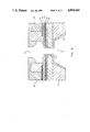
- FIG. 1 A prior-art thermal ink jet printhead 2 is shown in FIG. 1.
- the advancement of thermal ink jet (TIJ) technology falls upon an assembly problem: detachment of the nozzle plate 1.
- each nozzle plate 1 is individually attached to the resistor structure 3 as shown in FIG. 2A.
- This costly procedure is problem-prone. For example, this procedure often misaligns the nozzle plate 1.
- FIG. 2A a simplified representation of the prior art, omits many of the details.
- the differences in thermal expansion coefficients among different components of the TIJ printhead 2 tend to debond the nozzle plate 1 during the curing process of the glue. This adhesion problem limits the number of nozzles in the TIJ printhead 2.
- prior-art TIJ printhead 2 presents another problem. It limits the printing speed.
- ink reaches the nozzle 6 after traveling through high friction channels 7 which restrict the ink flow.
- the present invention a monolithic thermal ink jet printhead with integrated nozzle and ink well and a process for making it, solves the nozzle attachment and ink flow problems of prior-art printheads mentioned above. Also, the present invention reduces manufacturing costs and improves reliability. The reduced manufacturing costs are partially achieved through an automated manufacturing procedure. The increased reliability is partially achieved through longer resistor life and smoother ink flow in the printhead. Without these improvements, page-width TIJ print arrays would not be possible.
- FIG. 3 Further advantages of the present invention include the automatically-aligned nozzle 19, shown in FIG. 3.
- Prior-art processes misalign the nozzle plate 1 shown in FIG. 1. This misalignment causes dot spread and slanted printing.
- the new monolithic TIJ printhead 20 reduces resistor failure.
- prior-art TIJ printheads shown in FIG. 1 the collapsing bubble and refilling ink impact the resistor surface. The cavitation force eventually destroys the resistor.
- the collapsing bubble collides with the refilling ink. The ink absorbs most of the cavitation forces.
- printing speed is not limited by the ink refilling rate.
- the ink well 11 is directly connected to the heating elements 15 as shown in FIG. 3. This direct connection reduces resistance to ink flow.
- printing speed is not limited by the ink refilling rate.
- FIG. 1 shows a prior-art thermal ink jet printhead.
- FIG. 2A shows a cross section of a prior-art nozzle.
- FIG. 2B shows a top view of a prior-art nozzle, the cut 2--2 corresponds to the cross section of FIG. 2A.
- FIG. 3 shows a cross-section of the preferred embodiment of the invention with cantilever beams.
- FIG. 4 shows a top view of the preferred embodiment of the invention with the nozzle removed; the cut 3--3 corresponds to the cross-section of FIG. 3.
- FIGS. 5A-5F show steps in preparing the substrate for masking.
- FIGS. 6A-6C shows the formation of the cantilever beams and the well.
- FIG. 7A shows the formation of the resistor layer and a protective layer.
- FIG. 7B shows the formation of the conducting layer for the nozzle and the donut-shaped frame for the nozzle.
- FIGS. 8A, 8B, and 8C show the steps taken to construct the nozzle shown in FIG. 3.
- FIG. 9 shows an alternate embodiment of the invention without cantilever beams.
- FIG. 10 shows a top view of the alternate embodiment shown in FIG. 9.
- FIG. 11 is a cut-away isometric view of a thermal ink jet printhead showing only a single cantilevered heater resistor for sake of brevity and cut-away at the center line of the heater resistor.
- FIG. 11 is taken along lines 11--11 of FIG. 12.
- FIG. 12 is a plan view taken along lines 12--12 of FIG. 11.
- FIG. 3 shows a cross-section of the preferred embodiment of the invention, a monolithic thermal ink jet printhead with integrated nozzle 19 and ink well 11.
- FIG. 4 shows a top view of the monolithic printhead 20. Inside the substrate 10 a well 11 resides to hold ink. The heating element, a resistor layer 15, evaporates the ink. The ink (water vapor, glycol, and ink pigment particles) migrates to the nozzle area 17. The compound bore nozzle 19 directs the gaseous ink as it is expelled from the nozzle area 17 by pressure from the accumulated ink.
- a thermal barrier layer 21 prevents heat from flowing to the nickel cantilever beams 12 and nickel substrate 40. With this arrangement, heat from the resistive layer 15 heats the ink and is not wasted on the printhead 20.
- a patterned conducting layer 23 shorts out the resistive layer 15 except on the cantilever beams 12.
- a protective layer 25 prevents electrical shorts during the nickel plating process to form the nozzle 19. The protective layer 25 also protects layers from chemical and mechanical wear.
- a conducting layer 27 is deposited during the manufacturing process to provide a surface upon which the nozzle 19 can be constructed.
- the process to manufacture monolithic thermal ink jet printheads 20 involves several steps. On a substrate 10 of glass or silicon shown in FIG. 5A, a conducting layer 30 approximately 1000 ⁇ is deposited using a sputter deposition technique. By conducting electricity through the conducting layer 30, a surface is formed to which nickel plating can be attached. Next, a dry film mask 32 is laminated on the conducting layer 30 as shown in FIG. 5B. This mask 32, having a diameter of 2 to 3 mils, defines the location of the cantilever beams 12 in FIG. 3 as well as 13 in FIG. 9. FIGS. 5C, 5D, 5D, 5E and 5F show the various shapes a mask 32 can have.
- Mask 38 corresponds to the printhead 20 shown in FIGS. 3 and 4.
- Mask 34 corresponds to printhead 60 shown in FIGS. 9 and 10.
- the mask 39 corresponds to printhead shown in FIGS. 11 and 12.
- an electroplating process deposits a nickel layer 40 from 1 to 1.5 mils thick onto the exposed substrate 10.
- cantilever beams 12 are formed.
- removal of the dry film mask 38 exposes the cantilever beams 12 shown in FIG. 6B.
- the well 11 is formed through a multi-step process.
- a sputtering process deposits a protective metal layer 42. This layer is made of gold and has a thickness of 1000 ⁇ .
- a mask 44 defines the well 11.
- a wet chemical etching process such as KOH for silicon or HF for glass, forms the well 11.
- the protective layer 42 and the mask layer 44 are removed, the device appears as shown in FIG. 6C.
- the conductive layer at the bottom of the well 11 is then removed using a selected metal etchant.
- the thermal insulation layer 21 encourages the efficient operation of the resistor layer 15.
- a resistive layer 15 made of material such as tantalum-aluminum is deposited to a thickness of 1000 ⁇ to 5000 ⁇ as shown in FIGS. 3 and 7A.
- a conducting layer 23 made of gold or aluminum to a thickness of 5000 ⁇ is selectively patterned on resistive layer 15 to short out portions of the resistive layer 15.
- the conducting layer 23 is not present on the cantilever beam 12 so that the resistive layer 15 is operative there.
- a protective layer 25 made of silicon carbide, SiC, silicon nitride, Si 3 N 4 , or other dielectric material is deposited using a low pressure chemical vapor deposition (LPCVD) process. This layer protects the device from chemical and mechanical wear.
- LPCVD low pressure chemical vapor deposition
- the conducting layer 27 provides a surface upon which the nozzle 19 can be formed with an electroplating process.
- portions of the conducting layer 27 are etched away through a wet-etching process as shown in FIG. 7B, so that the only conducting layer 27 remaining is located where the nozzle will be constructed.
- donut-shaped dry film blocks 52 are laminated onto the conducting layer 27. These blocks 52 form a frame for the construction of the nozzle 19.
- the nozzle 19 is constructed in a two-step plating process. The results of the first step are shown in FIG. 8A.
- the base of nozzle 19 is formed by electroplating nickel onto the conducting layer 27 to a thickness of 1.5 mil to 2.0 mil, which equals the height of the nozzle 19.
- a glass slab or any other flat dielectric material 56 is pressed on the nozzle 19 as shown in FIG. 8B. This slab 56 acts as a nozzle 19 mold for the second part of the nickel plating process.
- FIG. 8C the electroplating process is continued to form the nozzle 19.
- the slab 56 is removed.
- the resulting product is the printhead 20 shown in FIG. 3.
- Other methods can be used to form the nozzle 19.
- the nozzle 19 could be constructed through a one-step plating process without the use of the slab 56.
- FIG. 9 shows an alternate embodiment of the printhead 20.
- a nozzle 19 having this shape is called a compound-bore nozzle 19. It controls the stream of ink ejected from the nozzle 19.
- the ink stream ejected from a compound-bore nozzle has a narrow diameter and minimum spread.
- the cantilever beams 13 protrude inward and the heating element 15 rests on top of the cantilever beam 13.
- This embodiment of the printhead 20 would be formed in the same way as the printhead 20 shown in FIG. 3.
- the primary difference in the process would be in the type of mask 32 used when layer 40 is placed onto substrate 10. Instead of mask 38 for the cantilever beams 12, a mask similar to mask 34 is used.
- FIG. 11 this view is cut-away at the center line of the cantilevered heater resistor 60 which is disposed on top of an insulator material 62.
- the insulator material 62 is shown as only a single layer in FIG. 11 for sake of brevity, but it will be understood that this insulating material 62 may be formed of multiple insulating and protective layers in the same manner as described above with reference to earlier figures.
- the insulating material 62 is formed around the cantilever beam 64 which extends from one side to the other of the ink reservoir walls 66.
- These walls 66 partially define the ink flow paths on each side of the cantilever beam 64 and these paths receive ink from the lower ink reservoir beneath the heater resistor 60 and defined by the slanted walls of insulating material 68 which cover the previously etched substrate 70. This etching step has been previously described with respect to the fabrication of the structures in FIGS. 3 and 9.
- the substrate 70 of either glass or silicon, for example, is initially covered with a flexible support layer 72 of nickel plating which of course is the same material that forms the cantilever beam 64.
- the heater resistor 60 on the top of the beam 64 is electrically interconnected to a conductive trace or strip 74 which is shown only at one side of the resistor 60, but will also exist at the other side of the resistor 60 and not shown in FIG. 11.
- a seed layer is patterned as indicated at 76 to form the necessary nickel seed growth material for the orifice plate to be formed, and a dry polymer film is patterned in a manner previously described to leave an annular ring 78 encircling the cantilevered resistor 60 and its associated ink flow port surrounding the resistor.
- This annular ring 78 serves to define the upper ink reservoir area over the heater resistor 60.
- This annular ring 78 may, for example, be fabricated of a polymer material such as RISTON or VACREL available from the DuPont Company, and is used to define the convergent orifice geometry for the upper nickel nozzle plate 80.
- the nozzle plate 80 may be formed in a two step process as described above to provide the converging orifice surfaces 82 which terminate at the output orifice opening 84 on the outer surface of the orifice plate 80.
- the preference for this convergent orifice geometry is described in more detail in U.S. Pat. No. 4,694,308 issued to C. S. Chan et al, assigned to the present assignee and incorporated herein by reference.
- the center line of the orifice opening 84 may be either precisely aligned with respect to the resistor 60, or in some structures it may be desired to provide a predetermined offset between the center line of the orifice 84 and the mid point of the heater resistor 60.
- the printhead ejects ink which contains water, glycol, and pigment particles.
- ink which contains water, glycol, and pigment particles.
- it can be used to eject other substances.
Abstract
A monolithic thermal ink jet printhead is presented. This monolithic structure makes page-width array thermal ink jet printheads possible. The monolithic structure can be manufactured by standard integrated circuit and printed circuit processing techniques. A nickel-plating process constructs a nozzle on top of resistors, thereby eliminating adhesion and alignment problems. A rigid substrate supports a flexible cantilever beam upon which the resistors are constructed. The cantilever beam, together with the ink itself, buffers the impact of cavitation forces during bubble collapsing and results in a better resistor reliablility. The monolithic printhead allows a smoother ink supply since the ink is fed directly from the backside to the resistor through an opening in the rigid substrate. The orifice structure is constructed by a self-aligned, two-step plating process which results in compound bore shape nozzles.
Description
This application is a continuation-in-part of my earlier parent application Ser. No. 856,740, filed Apr. 28, 1986, now abandoned.
A prior-art thermal ink jet printhead 2 is shown in FIG. 1. The advancement of thermal ink jet (TIJ) technology stumbles upon an assembly problem: detachment of the nozzle plate 1. Presently, each nozzle plate 1 is individually attached to the resistor structure 3 as shown in FIG. 2A. This costly procedure is problem-prone. For example, this procedure often misaligns the nozzle plate 1. FIG. 2A, a simplified representation of the prior art, omits many of the details. The differences in thermal expansion coefficients among different components of the TIJ printhead 2 tend to debond the nozzle plate 1 during the curing process of the glue. This adhesion problem limits the number of nozzles in the TIJ printhead 2.
The ink refilling rate of prior-art TIJ printhead 2 presents another problem. It limits the printing speed. In prior-art TIJ printheads 2 shown in FIG. 2B, ink reaches the nozzle 6 after traveling through high friction channels 7 which restrict the ink flow.
The invention described in U.S. Pat. No. 4,438,191, Monolithic Ink Jet Print Head, incorporated herein by reference, proposes a monolithic ink jet printhead that would solve some of the problems listed above. However, the fabrication of this device presents additional problems: formation of ink holes, removal of dry film residue from the firing chambers and other locations, proper alignment of the nozzle, and various manufacturing problems. Also, the nozzles of the monolithic printhead do not diverge.
The present invention, a monolithic thermal ink jet printhead with integrated nozzle and ink well and a process for making it, solves the nozzle attachment and ink flow problems of prior-art printheads mentioned above. Also, the present invention reduces manufacturing costs and improves reliability. The reduced manufacturing costs are partially achieved through an automated manufacturing procedure. The increased reliability is partially achieved through longer resistor life and smoother ink flow in the printhead. Without these improvements, page-width TIJ print arrays would not be possible.
Further advantages of the present invention include the automatically-aligned nozzle 19, shown in FIG. 3. Prior-art processes misalign the nozzle plate 1 shown in FIG. 1. This misalignment causes dot spread and slanted printing. The new monolithic TIJ printhead 20 reduces resistor failure. In prior-art TIJ printheads shown in FIG. 1, the collapsing bubble and refilling ink impact the resistor surface. The cavitation force eventually destroys the resistor. In the new monolithic TIJ printhead 20 shown in FIG. 3, the collapsing bubble collides with the refilling ink. The ink absorbs most of the cavitation forces. The cantilever beams 12, upon which the heating element, such as a resistor, is built, absorb the remaining cavitation force. The cantilever beams, constructed from ductile nickel, float in a reservoir of ink. The mechanical forces on resistors will be buffered by the flexibility of the cantilever beams as well as the ink itself.
Also, in the present invention printing speed is not limited by the ink refilling rate. The ink well 11 is directly connected to the heating elements 15 as shown in FIG. 3. This direct connection reduces resistance to ink flow. Thus, printing speed is not limited by the ink refilling rate.
FIG. 1 shows a prior-art thermal ink jet printhead.
FIG. 2A shows a cross section of a prior-art nozzle.
FIG. 2B shows a top view of a prior-art nozzle, the cut 2--2 corresponds to the cross section of FIG. 2A.
FIG. 3 shows a cross-section of the preferred embodiment of the invention with cantilever beams.
FIG. 4 shows a top view of the preferred embodiment of the invention with the nozzle removed; the cut 3--3 corresponds to the cross-section of FIG. 3.
FIGS. 5A-5F show steps in preparing the substrate for masking.
FIGS. 6A-6C shows the formation of the cantilever beams and the well.
FIG. 7A shows the formation of the resistor layer and a protective layer.
FIG. 7B shows the formation of the conducting layer for the nozzle and the donut-shaped frame for the nozzle.
FIGS. 8A, 8B, and 8C show the steps taken to construct the nozzle shown in FIG. 3.
FIG. 9 shows an alternate embodiment of the invention without cantilever beams.
FIG. 10 shows a top view of the alternate embodiment shown in FIG. 9.
FIG. 11 is a cut-away isometric view of a thermal ink jet printhead showing only a single cantilevered heater resistor for sake of brevity and cut-away at the center line of the heater resistor. FIG. 11 is taken along lines 11--11 of FIG. 12.
FIG. 12 is a plan view taken along lines 12--12 of FIG. 11.
FIG. 3 shows a cross-section of the preferred embodiment of the invention, a monolithic thermal ink jet printhead with integrated nozzle 19 and ink well 11. FIG. 4 shows a top view of the monolithic printhead 20. Inside the substrate 10 a well 11 resides to hold ink. The heating element, a resistor layer 15, evaporates the ink. The ink (water vapor, glycol, and ink pigment particles) migrates to the nozzle area 17. The compound bore nozzle 19 directs the gaseous ink as it is expelled from the nozzle area 17 by pressure from the accumulated ink.
A thermal barrier layer 21 prevents heat from flowing to the nickel cantilever beams 12 and nickel substrate 40. With this arrangement, heat from the resistive layer 15 heats the ink and is not wasted on the printhead 20. A patterned conducting layer 23 shorts out the resistive layer 15 except on the cantilever beams 12. A protective layer 25 prevents electrical shorts during the nickel plating process to form the nozzle 19. The protective layer 25 also protects layers from chemical and mechanical wear. A conducting layer 27 is deposited during the manufacturing process to provide a surface upon which the nozzle 19 can be constructed.
The process to manufacture monolithic thermal ink jet printheads 20 involves several steps. On a substrate 10 of glass or silicon shown in FIG. 5A, a conducting layer 30 approximately 1000 Å is deposited using a sputter deposition technique. By conducting electricity through the conducting layer 30, a surface is formed to which nickel plating can be attached. Next, a dry film mask 32 is laminated on the conducting layer 30 as shown in FIG. 5B. This mask 32, having a diameter of 2 to 3 mils, defines the location of the cantilever beams 12 in FIG. 3 as well as 13 in FIG. 9. FIGS. 5C, 5D, 5D, 5E and 5F show the various shapes a mask 32 can have. Mask 38 corresponds to the printhead 20 shown in FIGS. 3 and 4. Mask 34 corresponds to printhead 60 shown in FIGS. 9 and 10. The mask 39 corresponds to printhead shown in FIGS. 11 and 12.
Next, an electroplating process deposits a nickel layer 40 from 1 to 1.5 mils thick onto the exposed substrate 10. Thus, cantilever beams 12 are formed. After completion of the plating, removal of the dry film mask 38 exposes the cantilever beams 12 shown in FIG. 6B. The well 11 is formed through a multi-step process. First, a sputtering process deposits a protective metal layer 42. This layer is made of gold and has a thickness of 1000 Å. Next, a mask 44 defines the well 11. Then, a wet chemical etching process, such as KOH for silicon or HF for glass, forms the well 11. When the protective layer 42 and the mask layer 44 are removed, the device appears as shown in FIG. 6C. The conductive layer at the bottom of the well 11 is then removed using a selected metal etchant.
Next, a thermal insulating layer 21, made of LPCVD SiO2 or another dielectric, is deposited. It is deposited to a thickness of 1.5 microns on the inside of the well 11, on top of the plated nickel layer 40, and around the cantilever beams 12 as shown in FIGS. 3 and 7A. The thermal insulation layer 21 encourages the efficient operation of the resistor layer 15. On top of the thermal insulating layer 21, a resistive layer 15 made of material such as tantalum-aluminum is deposited to a thickness of 1000 Å to 5000 Å as shown in FIGS. 3 and 7A. Next, a conducting layer 23 made of gold or aluminum to a thickness of 5000 Å is selectively patterned on resistive layer 15 to short out portions of the resistive layer 15. The conducting layer 23 is not present on the cantilever beam 12 so that the resistive layer 15 is operative there. On top of the conducting layer 23, a protective layer 25 made of silicon carbide, SiC, silicon nitride, Si3 N4, or other dielectric material is deposited using a low pressure chemical vapor deposition (LPCVD) process. This layer protects the device from chemical and mechanical wear.
A conducting layer 27, 1000 to 5000 Å thick, is deposited on the protective layer 25. It is formed by sputtering. The conducting layer 27 provides a surface upon which the nozzle 19 can be formed with an electroplating process. Next, portions of the conducting layer 27 are etched away through a wet-etching process as shown in FIG. 7B, so that the only conducting layer 27 remaining is located where the nozzle will be constructed.
Next, donut-shaped dry film blocks 52 are laminated onto the conducting layer 27. These blocks 52 form a frame for the construction of the nozzle 19. In the preferred embodiment of the invention, the nozzle 19 is constructed in a two-step plating process. The results of the first step are shown in FIG. 8A. The base of nozzle 19 is formed by electroplating nickel onto the conducting layer 27 to a thickness of 1.5 mil to 2.0 mil, which equals the height of the nozzle 19. Next, a glass slab or any other flat dielectric material 56 is pressed on the nozzle 19 as shown in FIG. 8B. This slab 56 acts as a nozzle 19 mold for the second part of the nickel plating process. FIG. 8C, the electroplating process is continued to form the nozzle 19. Now that the nozzle 19 is completed, the slab 56 is removed. The resulting product is the printhead 20 shown in FIG. 3. Other methods can be used to form the nozzle 19. For example, the nozzle 19 could be constructed through a one-step plating process without the use of the slab 56.
FIG. 9 shows an alternate embodiment of the printhead 20. A nozzle 19 having this shape is called a compound-bore nozzle 19. It controls the stream of ink ejected from the nozzle 19. The ink stream ejected from a compound-bore nozzle has a narrow diameter and minimum spread. The cantilever beams 13 protrude inward and the heating element 15 rests on top of the cantilever beam 13. This embodiment of the printhead 20 would be formed in the same way as the printhead 20 shown in FIG. 3. The primary difference in the process would be in the type of mask 32 used when layer 40 is placed onto substrate 10. Instead of mask 38 for the cantilever beams 12, a mask similar to mask 34 is used.
Referring now to FIG. 11, this view is cut-away at the center line of the cantilevered heater resistor 60 which is disposed on top of an insulator material 62. The insulator material 62 is shown as only a single layer in FIG. 11 for sake of brevity, but it will be understood that this insulating material 62 may be formed of multiple insulating and protective layers in the same manner as described above with reference to earlier figures. The insulating material 62 is formed around the cantilever beam 64 which extends from one side to the other of the ink reservoir walls 66. These walls 66 partially define the ink flow paths on each side of the cantilever beam 64 and these paths receive ink from the lower ink reservoir beneath the heater resistor 60 and defined by the slanted walls of insulating material 68 which cover the previously etched substrate 70. This etching step has been previously described with respect to the fabrication of the structures in FIGS. 3 and 9.
The substrate 70 of either glass or silicon, for example, is initially covered with a flexible support layer 72 of nickel plating which of course is the same material that forms the cantilever beam 64. The heater resistor 60 on the top of the beam 64 is electrically interconnected to a conductive trace or strip 74 which is shown only at one side of the resistor 60, but will also exist at the other side of the resistor 60 and not shown in FIG. 11.
A seed layer is patterned as indicated at 76 to form the necessary nickel seed growth material for the orifice plate to be formed, and a dry polymer film is patterned in a manner previously described to leave an annular ring 78 encircling the cantilevered resistor 60 and its associated ink flow port surrounding the resistor. This annular ring 78 serves to define the upper ink reservoir area over the heater resistor 60. This annular ring 78 may, for example, be fabricated of a polymer material such as RISTON or VACREL available from the DuPont Company, and is used to define the convergent orifice geometry for the upper nickel nozzle plate 80. The nozzle plate 80 may be formed in a two step process as described above to provide the converging orifice surfaces 82 which terminate at the output orifice opening 84 on the outer surface of the orifice plate 80. The preference for this convergent orifice geometry is described in more detail in U.S. Pat. No. 4,694,308 issued to C. S. Chan et al, assigned to the present assignee and incorporated herein by reference.
Thus, from the cut-away isometric view in FIG. 11 and its associated plan view of FIG. 12, it is clearly seen that not only does this printhead structure provide for an improved ink flow rate to the resistive heater 60, but it simultaneously provides for the cooling of the heater resistor 60 and it simultaneously minimizes the cavitation wear received by the heater resistor 60. This is partially the result of the flexible nature of the cantilever beam 64 which allows the surrounding ink to receive and absorb cavitational forces resulting from ink ejection. During the flexing of this cantilever beam 64 during an ink jet printing operation, cavitational forces transmitted to the heater resistor 60 from the output orifice 82, 84 are retransmitted to the surrounding ink where the resistor 60 is simultaneously cooled. And, the cooling of the heater resistor 60 is a very significant feature of present invention and its ability to maximize resistor and orifice packing density within the ink jet printhead.
Finally, using the polymer masking and nickel electroforming techniques previously described to define the geometry of the orifice plate 80, the center line of the orifice opening 84 may be either precisely aligned with respect to the resistor 60, or in some structures it may be desired to provide a predetermined offset between the center line of the orifice 84 and the mid point of the heater resistor 60.
In the preferred embodiment of the invention, the printhead ejects ink which contains water, glycol, and pigment particles. However, it can be used to eject other substances.
Claims (5)
1. A process for increasing the lifetime of a resistive heater element in a thermal ink jet printhead of the type having an orifice plate mounted on a thin film substrate, including the steps of:
a. providing a flexible suspended beam containing a resistive heater element in an ink reservoir of said thin film substrate and extending from one side of said reservoir to another, and
b. providing electrical connections into said resistive heater element, whereby the utilization of said suspended beam in the ink within said reservoir allows the ink to cool said heater element and to absorb cavitational forces produced by ink ejected from said orifice plate and thereby increase printhead lifetime.
2. The process defined in claim 1 which further includes:
a. plating a metal orifice layer on said thin film substrate, and
b. controlling the radial growth of said metal orifice layer in a manner so as to leave an orifice opening in said metal orifice layer which is self aligned with respect to said resistive heater element.
3. A thermal ink jet printhead of the type having an orifice plate mounted on a thin film substrate and characterized by extended lifetimes of resistive heater elements therein, comprising:
a. a flexible suspended beam containing a resistive heater element and extending from one side of an ink reservoir to another within said substrate, and
b. electrical connections extending to each side of said resistive heater element, whereby the suspended beam in ink within said reservoir allows the ink to cool said resistive heater element and to absorb cavitational forces produced by the ejection of ink from said orifice plate, to thereby increase printhead lifetime.
4. A thermal ink jet printhead characterized by the precise alignment of an orifice plate mounted on top a thin film substrate and comprising:
a. a resistive heater element located within said substrate and having electrical conductors connected thereto for providing pulses to said resistive heater element during an ink jet printing operation,
b. a metal orifice layer plated on said thin film substrate and extending upwardly and inwardly above said resistive heater element and having a convergent orifice opening above said resistive heater element which is self aligned with respect to said resistive heater element, and
c. said resistive heater element being mounted on a flexible suspended beam extending from one side of an ink reservoir to another and aligned with said opening in said orifice plate, whereby the flow of ink is readily accessible from said reservoir to both sides of said resistive heater element during an ink jet printing operation, and the suspension of said heater resistor within said reservoir allows the ink to both cool said resistor and absorb cavitational forces produced by ink ejected from said orifice plate, thereby decreasing resistor wear and increasing printhead lifetime.
5. The printhead defined in claim 4 wherein said thin film substrate has a barrier layer thereon aligned to said resistive heater element, and an opening in said orifice plate is aligned to said barrier layer, whereby said orifice plate opening is self aligned to said resistive heater element.
Priority Applications (2)
| Application Number | Priority Date | Filing Date | Title |
|---|---|---|---|
| US07/125,433 US4894664A (en) | 1986-04-28 | 1987-11-25 | Monolithic thermal ink jet printhead with integral nozzle and ink feed |
| US07/357,915 US4922265A (en) | 1986-04-28 | 1989-05-30 | Ink jet printhead with self-aligned orifice plate and method of manufacture |
Applications Claiming Priority (2)
| Application Number | Priority Date | Filing Date | Title |
|---|---|---|---|
| US85674086A | 1986-04-28 | 1986-04-28 | |
| US07/125,433 US4894664A (en) | 1986-04-28 | 1987-11-25 | Monolithic thermal ink jet printhead with integral nozzle and ink feed |
Related Parent Applications (1)
| Application Number | Title | Priority Date | Filing Date |
|---|---|---|---|
| US85674086A Continuation-In-Part | 1986-04-28 | 1986-04-28 |
Related Child Applications (1)
| Application Number | Title | Priority Date | Filing Date |
|---|---|---|---|
| US07/357,915 Division US4922265A (en) | 1986-04-28 | 1989-05-30 | Ink jet printhead with self-aligned orifice plate and method of manufacture |
Publications (1)
| Publication Number | Publication Date |
|---|---|
| US4894664A true US4894664A (en) | 1990-01-16 |
Family
ID=26823583
Family Applications (1)
| Application Number | Title | Priority Date | Filing Date |
|---|---|---|---|
| US07/125,433 Expired - Fee Related US4894664A (en) | 1986-04-28 | 1987-11-25 | Monolithic thermal ink jet printhead with integral nozzle and ink feed |
Country Status (1)
| Country | Link |
|---|---|
| US (1) | US4894664A (en) |
Cited By (141)
| Publication number | Priority date | Publication date | Assignee | Title |
|---|---|---|---|---|
| DE4016500A1 (en) * | 1990-05-22 | 1990-10-11 | Siemens Ag | Ink jet printer - has improved jet repetition capability and uses pressure bubbles resulting from heating ink to transform into print jet |
| US5059973A (en) * | 1989-02-03 | 1991-10-22 | Canon Kabushiki Kaisha | Ink jet head formed by bonding a discharge port plate to a main body |
| DE4025619A1 (en) * | 1990-08-13 | 1992-02-20 | Siemens Ag | Line setter for ink droplet printer - has cantilever heating resistance in each nozzle chamber with electronic heating controller |
| US5148185A (en) * | 1986-06-10 | 1992-09-15 | Seiko Epson Corporation | Ink jet recording apparatus for ejecting droplets of ink through promotion of capillary action |
| US5272491A (en) * | 1990-10-31 | 1993-12-21 | Hewlett-Packard Company | Thermal ink jet print device having phase change cooling |
| US5455613A (en) * | 1990-10-31 | 1995-10-03 | Hewlett-Packard Company | Thin film resistor printhead architecture for thermal ink jet pens |
| US5706041A (en) * | 1996-03-04 | 1998-01-06 | Xerox Corporation | Thermal ink-jet printhead with a suspended heating element in each ejector |
| EP0820870A2 (en) * | 1996-07-22 | 1998-01-28 | Eastman Kodak Company | Ink printing apparatus with improved heater |
| US5751315A (en) * | 1996-04-16 | 1998-05-12 | Xerox Corporation | Thermal ink-jet printhead with a thermally isolated heating element in each ejector |
| US5847737A (en) * | 1996-06-18 | 1998-12-08 | Kaufman; Micah Abraham | Filter for ink jet printhead |
| US5871158A (en) * | 1997-01-27 | 1999-02-16 | The University Of Utah Research Foundation | Methods for preparing devices having metallic hollow microchannels on planar substrate surfaces |
| US5874974A (en) * | 1992-04-02 | 1999-02-23 | Hewlett-Packard Company | Reliable high performance drop generator for an inkjet printhead |
| US5901425A (en) | 1996-08-27 | 1999-05-11 | Topaz Technologies Inc. | Inkjet print head apparatus |
| US5984464A (en) * | 1992-04-02 | 1999-11-16 | Hewlett-Packard Company | Stable substrate structure for a wide swath nozzle array in a high resolution inkjet printer |
| US6000787A (en) * | 1996-02-07 | 1999-12-14 | Hewlett-Packard Company | Solid state ink jet print head |
| US6003977A (en) * | 1996-02-07 | 1999-12-21 | Hewlett-Packard Company | Bubble valving for ink-jet printheads |
| US6019457A (en) * | 1991-01-30 | 2000-02-01 | Canon Information Systems Research Australia Pty Ltd. | Ink jet print device and print head or print apparatus using the same |
| US6065823A (en) * | 1999-04-16 | 2000-05-23 | Hewlett-Packard Company | Heat spreader for ink-jet printhead |
| US6084615A (en) * | 1998-03-23 | 2000-07-04 | Microjet Technology Co., Ltd. | Structure of inkjet nozzle for ink cartridge |
| US6086187A (en) * | 1989-05-30 | 2000-07-11 | Canon Kabushiki Kaisha | Ink jet head having a silicon intermediate layer |
| US6093330A (en) * | 1997-06-02 | 2000-07-25 | Cornell Research Foundation, Inc. | Microfabrication process for enclosed microstructures |
| US6113221A (en) * | 1996-02-07 | 2000-09-05 | Hewlett-Packard Company | Method and apparatus for ink chamber evacuation |
| US6137443A (en) * | 1997-10-22 | 2000-10-24 | Hewlett-Packard Company | Single-side fabrication process for forming inkjet monolithic printing element array on a substrate |
| WO2001003934A1 (en) | 1999-07-12 | 2001-01-18 | Olivetti Lexikon S.P.A. | Monolithic printhead and associated manufacturing process |
| US6180536B1 (en) | 1998-06-04 | 2001-01-30 | Cornell Research Foundation, Inc. | Suspended moving channels and channel actuators for microfluidic applications and method for making |
| US6183076B1 (en) * | 1992-04-02 | 2001-02-06 | Hewlett-Packard Company | Printer having multi-chamber print cartridges and off-carriage regulator |
| WO2001008891A1 (en) * | 1999-07-30 | 2001-02-08 | Lexmark International, Inc. | Improved printhead configuration |
| EP1078755A1 (en) * | 1999-08-27 | 2001-02-28 | Hewlett-Packard Company | Fully integrated thermal inkjet printhead having multiple ink feed holes per nozzle |
| US6214192B1 (en) * | 1998-12-10 | 2001-04-10 | Eastman Kodak Company | Fabricating ink jet nozzle plate |
| WO2001034620A2 (en) * | 1999-11-10 | 2001-05-17 | Merckle Gmbh | Method and device for producing oligomers and arrays of oligomers and the use of said device |
| EP1078753A3 (en) * | 1999-08-27 | 2001-06-13 | Hewlett-Packard Company, A Delaware Corporation | Fully integrated thermal inkjet printhead having thin film layer shelf |
| EP1078754A3 (en) * | 1999-08-27 | 2001-06-13 | Hewlett-Packard Company, A Delaware Corporation | Fully integrated thermal inkjet printhead having etched back phosphosilicate glass layer |
| US6273557B1 (en) * | 1998-03-02 | 2001-08-14 | Hewlett-Packard Company | Micromachined ink feed channels for an inkjet printhead |
| US6276775B1 (en) | 1999-04-29 | 2001-08-21 | Hewlett-Packard Company | Variable drop mass inkjet drop generator |
| US6296452B1 (en) | 2000-04-28 | 2001-10-02 | Agilent Technologies, Inc. | Microfluidic pumping |
| US6299294B1 (en) | 1999-07-29 | 2001-10-09 | Hewlett-Packard Company | High efficiency printhead containing a novel oxynitride-based resistor system |
| WO2001076877A1 (en) * | 2000-04-10 | 2001-10-18 | Olivetti Tecnost S.P.A. | Monolithic printhead with multiple ink feeder channels and relative manufacturing process |
| US6310639B1 (en) | 1996-02-07 | 2001-10-30 | Hewlett-Packard Co. | Printer printhead |
| US6309054B1 (en) * | 1998-10-23 | 2001-10-30 | Hewlett-Packard Company | Pillars in a printhead |
| WO2001094117A1 (en) * | 2000-06-05 | 2001-12-13 | Olivetti Tecnost S.P.A. | Process for manufacturing a monolithic printhead with truncated cone shape nozzles |
| US6336713B1 (en) | 1999-07-29 | 2002-01-08 | Hewlett-Packard Company | High efficiency printhead containing a novel nitride-based resistor system |
| FR2811588A1 (en) * | 2000-07-13 | 2002-01-18 | Centre Nat Rech Scient | HEAT INJECTION AND DOSING HEAD, MANUFACTURING METHOD THEREOF, AND FUNCTIONALIZATION OR ADDRESSING SYSTEM COMPRISING THE SAME |
| EP1176017A1 (en) * | 2000-07-28 | 2002-01-30 | STMicroelectronics S.r.l. | Integrated semiconductor device including a heater for bringing about phase changes in microfluid systems |
| US6354695B1 (en) * | 2000-12-13 | 2002-03-12 | Samsung Electronics Co., Ltd. | Ink-jet printhead |
| US6382782B1 (en) | 2000-12-29 | 2002-05-07 | Eastman Kodak Company | CMOS/MEMS integrated ink jet print head with oxide based lateral flow nozzle architecture and method of forming same |
| US6398348B1 (en) * | 2000-09-05 | 2002-06-04 | Hewlett-Packard Company | Printing structure with insulator layer |
| US6402301B1 (en) | 2000-10-27 | 2002-06-11 | Lexmark International, Inc | Ink jet printheads and methods therefor |
| US6412928B1 (en) | 2000-12-29 | 2002-07-02 | Eastman Kodak Company | Incorporation of supplementary heaters in the ink channels of CMOS/MEMS integrated ink jet print head and method of forming same |
| EP1226947A1 (en) * | 2001-01-30 | 2002-07-31 | Hewlett-Packard Company | Thin film coating of a slotted substrate and techniques for forming slotted substrates |
| US6439703B1 (en) | 2000-12-29 | 2002-08-27 | Eastman Kodak Company | CMOS/MEMS integrated ink jet print head with silicon based lateral flow nozzle architecture and method of forming same |
| US6443557B1 (en) | 1999-10-29 | 2002-09-03 | Hewlett-Packard Company | Chip-carrier for improved drop directionality |
| US6471340B2 (en) * | 2001-02-12 | 2002-10-29 | Hewlett-Packard Company | Inkjet printhead assembly |
| US6474794B1 (en) | 2000-12-29 | 2002-11-05 | Eastman Kodak Company | Incorporation of silicon bridges in the ink channels of CMOS/MEMS integrated ink jet print head and method of forming same |
| US6481828B2 (en) * | 2000-12-16 | 2002-11-19 | Samsung Electronics Co., Ltd. | Ink-jet printhead having high nozzle density |
| US6482574B1 (en) | 2000-04-20 | 2002-11-19 | Hewlett-Packard Co. | Droplet plate architecture in ink-jet printheads |
| US6485128B1 (en) * | 1996-03-04 | 2002-11-26 | Hewlett-Packard Company | Ink jet pen with a heater element having a contoured surface |
| US6499832B2 (en) | 2000-04-26 | 2002-12-31 | Samsung Electronics Co., Ltd. | Bubble-jet type ink-jet printhead capable of preventing a backflow of ink |
| US6527378B2 (en) * | 2001-04-20 | 2003-03-04 | Hewlett-Packard Company | Thermal ink jet defect tolerant resistor design |
| US6533399B2 (en) | 2000-07-18 | 2003-03-18 | Samsung Electronics Co., Ltd. | Bubble-jet type ink-jet printhead and manufacturing method thereof |
| US6561632B2 (en) * | 2001-06-06 | 2003-05-13 | Hewlett-Packard Development Company, L.P. | Printhead with high nozzle packing density |
| US6595627B2 (en) * | 2001-11-15 | 2003-07-22 | Samsung Electronics Co., Ltd. | Inkjet printhead and manufacturing method thereof |
| US20030141277A1 (en) * | 1999-08-19 | 2003-07-31 | Christopher Beatty | Method of manufacturing a fluid ejection device with a fluid channel therethrough |
| US6626523B2 (en) * | 2001-10-31 | 2003-09-30 | Hewlett-Packard Development Company, Lp. | Printhead having a thin film membrane with a floating section |
| US6627467B2 (en) | 2001-10-31 | 2003-09-30 | Hewlett-Packard Development Company, Lp. | Fluid ejection device fabrication |
| US20030186474A1 (en) * | 2001-10-31 | 2003-10-02 | Haluzak Charles C. | Drop generator for ultra-small droplets |
| US20030193548A1 (en) * | 2002-04-15 | 2003-10-16 | Emery Timothy R. | Bonding structure and method of making |
| US20030227498A1 (en) * | 2002-06-07 | 2003-12-11 | Samii Mohammad M. | Fluid ejection system with photosensor activation of ejection element |
| US20030227495A1 (en) * | 2002-06-07 | 2003-12-11 | Samii Mohammad M. | Fluid ejection and scanning assembly with photosensor activation of ejection elements |
| US6679587B2 (en) * | 2001-10-31 | 2004-01-20 | Hewlett-Packard Development Company, L.P. | Fluid ejection device with a composite substrate |
| US6685302B2 (en) | 2001-10-31 | 2004-02-03 | Hewlett-Packard Development Company, L.P. | Flextensional transducer and method of forming a flextensional transducer |
| KR100421027B1 (en) * | 2002-04-29 | 2004-03-04 | 삼성전자주식회사 | Inkjet printhead and manufacturing method thereof |
| US6705701B2 (en) | 2002-06-07 | 2004-03-16 | Hewlett-Packard Development Company, L.P. | Fluid ejection and scanning system with photosensor activation of ejection elements |
| US6711806B2 (en) | 2001-05-14 | 2004-03-30 | Hewlett-Packard Development Company, L.P. | Method of manufacturing a thermal fluid jetting apparatus |
| US20040100535A1 (en) * | 2002-11-21 | 2004-05-27 | Hoon Song | Monolithic ink-jet printhead having a heater disposed between dual ink chambers and method for manufacturing the same |
| US6747684B2 (en) | 2002-04-10 | 2004-06-08 | Hewlett-Packard Development Company, L.P. | Laser triggered inkjet firing |
| US20040113985A1 (en) * | 2002-11-23 | 2004-06-17 | Silverbrook Research Pty Ltd | Heat dissipation within thermal ink jet printhead |
| US20040141027A1 (en) * | 2003-01-21 | 2004-07-22 | Truninger Martha A. | Substrate and method of forming substrate for fluid ejection device |
| US20040139608A1 (en) * | 2000-12-05 | 2004-07-22 | Hostetler Timothy S. | Slotted substrates and techniques for forming same |
| US20040176732A1 (en) * | 2000-06-02 | 2004-09-09 | Frazier A Bruno | Active needle devices with integrated functionality |
| US6799819B2 (en) | 2002-06-07 | 2004-10-05 | Hewlett-Packard Development Company, L.P. | Photosensor activation of an ejection element of a fluid ejection device |
| US20040246310A1 (en) * | 2003-06-05 | 2004-12-09 | Su-Ho Shin | Monolithic ink-jet printhead and method of manufacturing the same |
| US20050001886A1 (en) * | 2003-07-03 | 2005-01-06 | Scott Hock | Fluid ejection assembly |
| EP1518681A1 (en) * | 2003-09-24 | 2005-03-30 | Hewlett-Packard Development Company, L.P. | Inkjet printhead |
| US20050099466A1 (en) * | 1998-10-16 | 2005-05-12 | Kia Silverbrook | Printhead wafer with individual ink feed to each nozzle |
| US6895659B2 (en) * | 1998-10-26 | 2005-05-24 | Samsung Electronics Co., Ltd. | Process of manufacturing fluid jetting apparatuses |
| KR100506080B1 (en) * | 2000-12-15 | 2005-08-04 | 삼성전자주식회사 | Bubble-jet type ink-jet print head and manufacturing method thereof |
| US20050206679A1 (en) * | 2003-07-03 | 2005-09-22 | Rio Rivas | Fluid ejection assembly |
| US20050262691A1 (en) * | 2004-05-24 | 2005-12-01 | Seiko Epson Corporation | Manufacturing method of liquid jet head |
| US20050280670A1 (en) * | 2004-06-17 | 2005-12-22 | Industrial Technology Research Institute | Inkjet printhead |
| US20060044373A1 (en) * | 2004-08-30 | 2006-03-02 | Eastman Kodak Company | Liquid ejector having internal filters |
| US7048723B1 (en) | 1998-09-18 | 2006-05-23 | The University Of Utah Research Foundation | Surface micromachined microneedles |
| US20060119662A1 (en) * | 2004-12-02 | 2006-06-08 | Taiwan Semiconductor Manufacturing Co., Ltd. | Ink-channel wafer integrated with CMOS wafer for inkjet printhead and fabrication method thereof |
| KR100607166B1 (en) * | 2000-02-29 | 2006-08-01 | 삼성전자주식회사 | Liquid jet device and method thereof |
| US7104633B2 (en) * | 2001-11-02 | 2006-09-12 | Samsung Electronics Co., Ltd. | Monolithic ink-jet printhead and method of manufacturing the same |
| US20060238578A1 (en) * | 2005-04-26 | 2006-10-26 | Lebron Hector J | Fluid ejection assembly |
| US20060238577A1 (en) * | 2005-04-26 | 2006-10-26 | Hock Scott W | Fluid ejection assembly |
| US20070002098A1 (en) * | 2005-07-04 | 2007-01-04 | Park Yong-Shik | Inkjet printhead and method of manufacturing the same |
| KR100668295B1 (en) * | 2001-01-19 | 2007-01-12 | 삼성전자주식회사 | Ink-jet print head having semispherical ink chamber and method for manufacturing the same by using SOI wafer |
| US20070131648A1 (en) * | 2005-12-08 | 2007-06-14 | Shim Dong-Sik | Method of fabricating inkjet printhead |
| US20070261239A1 (en) * | 2006-05-11 | 2007-11-15 | Eastman Kodak Company | Electroformed integral charge plate and orifice plate for continuous ink jet printers |
| US20070261240A1 (en) * | 2006-05-11 | 2007-11-15 | Eastman Kodak Company | Charge plate and orifice plate for continuous ink jet printers |
| US20070263033A1 (en) * | 2006-05-11 | 2007-11-15 | Eastman Kodak Company | Integrated charge and orifice plates for continuous ink jet printers |
| US20070268338A1 (en) * | 2002-11-23 | 2007-11-22 | Silverbrook Research Pty Ltd | Inkjet Unit Cell With Dual Heater Elements |
| US20070268337A1 (en) * | 2002-11-23 | 2007-11-22 | Silverbrook Research Pty Ltd | Inkjet Unit Cell With Suspended Heater Element |
| US20080061341A1 (en) * | 2006-09-11 | 2008-03-13 | Macronix International Co., Ltd. | Memory Device Having Wide Area Phase Change Element and Small Electrode Contact Area |
| US20080088676A1 (en) * | 2002-11-23 | 2008-04-17 | Silverbrook Research Pty Ltd | Ink Jet Printhead With Suspended Heater Element |
| US20080088675A1 (en) * | 1997-07-15 | 2008-04-17 | Silverbrook Research Pty Ltd | Nozzle Arrangement For A Printhead Integrated Circuit Incorporating A Lever Mechanism |
| US20080111867A1 (en) * | 2005-04-04 | 2008-05-15 | Silverbrook Research Pty Ltd | Printhead unit cell incorporating a bubble generating heater element |
| US20080127471A1 (en) * | 2006-10-31 | 2008-06-05 | Seiko Epson Corporation | Method for manufacturing liquid ejecting head |
| US20090033720A1 (en) * | 2002-11-23 | 2009-02-05 | Silverbrook Research Pty Ltd | Printhead having efficient heater elements for small drop ejection |
| US20090040279A1 (en) * | 2007-07-30 | 2009-02-12 | Silverbrook Research Pty Ltd. | Inkjet printhead with non-uniform nozzle chamber inlets |
| US7568285B2 (en) | 2006-05-11 | 2009-08-04 | Eastman Kodak Company | Method of fabricating a self-aligned print head |
| US20090295870A1 (en) * | 2008-06-03 | 2009-12-03 | Richard Louis Goin | Nozzle plate for improved post-bonding symmetry |
| US20090307905A1 (en) * | 2005-12-27 | 2009-12-17 | Fuji Xerox Co., Ltd. | Droplet discharging head and manufacturing method for the same, and droplet discharging device |
| US20100067797A1 (en) * | 2002-11-05 | 2010-03-18 | Silverbrook Research Pty Ltd | Method of estimating digital ink orientation |
| US20100149278A1 (en) * | 2002-11-23 | 2010-06-17 | Silverbrook Research Pty Ltd | Printhead Having Low Energy Heating Circuitry |
| US20100214337A1 (en) * | 2007-07-30 | 2010-08-26 | Silverbrook Research Pty Ltd | Printer with resolution reduction by nozzle data sharing |
| US20100309252A1 (en) * | 1997-07-15 | 2010-12-09 | Silverbrook Research Pty Ltd | Ejection nozzle arrangement |
| US20110037796A1 (en) * | 1998-10-16 | 2011-02-17 | Silverbrook Research Pty Ltd | Compact nozzle assembly of an inkjet printhead |
| US20110049092A1 (en) * | 2009-08-26 | 2011-03-03 | Alfred I-Tsung Pan | Inkjet printhead bridge beam fabrication method |
| US20110096125A1 (en) * | 1997-07-15 | 2011-04-28 | Silverbrook Research Pty Ltd | Inkjet printhead with nozzle layer defining etchant holes |
| US20110109700A1 (en) * | 1997-07-15 | 2011-05-12 | Silverbrook Research Pty Ltd | Ink ejection mechanism with thermal actuator coil |
| US7950777B2 (en) | 1997-07-15 | 2011-05-31 | Silverbrook Research Pty Ltd | Ejection nozzle assembly |
| US20110134193A1 (en) * | 1997-07-15 | 2011-06-09 | Silverbrook Research Pty Ltd | Nozzle arrangement with an actuator having iris vanes |
| US20110157280A1 (en) * | 1997-07-15 | 2011-06-30 | Silverbrook Research Pty Ltd | Printhead nozzle arrangements with magnetic paddle actuators |
| US20110175970A1 (en) * | 1997-07-15 | 2011-07-21 | Silverbrook Research Pty Ltd | Inkjet printhead integrated circuit incorporating fulcrum assisted ink ejection actuator |
| US20110205303A1 (en) * | 2008-10-14 | 2011-08-25 | Hewlett-Packard Development Company, L.P. | Fluid ejector structure |
| US20110211025A1 (en) * | 1997-07-15 | 2011-09-01 | Silverbrook Research Pty Ltd | Printhead nozzle having heater of higher resistance than contacts |
| US20110228008A1 (en) * | 1997-07-15 | 2011-09-22 | Silverbrook Research Pty Ltd | Printhead having relatively sized fluid ducts and nozzles |
| US20110227987A1 (en) * | 2008-10-30 | 2011-09-22 | Alfred I-Tsung Pan | Thermal inkjet printhead feed transition chamber and method of cooling using same |
| US8029102B2 (en) | 1997-07-15 | 2011-10-04 | Silverbrook Research Pty Ltd | Printhead having relatively dimensioned ejection ports and arms |
| US20110261118A1 (en) * | 2010-04-27 | 2011-10-27 | Baumer Michael F | Printhead including integrated stimulator/filter device |
| US20110261117A1 (en) * | 2010-04-27 | 2011-10-27 | Yonglin Xie | Printhead stimulator/filter device printing method |
| US8061812B2 (en) | 1997-07-15 | 2011-11-22 | Silverbrook Research Pty Ltd | Ejection nozzle arrangement having dynamic and static structures |
| US20120047738A1 (en) * | 2010-09-01 | 2012-03-01 | Canon Kabushiki Kaisha | Method of manufacturing liquid discharge head |
| CN102470673A (en) * | 2009-07-31 | 2012-05-23 | 惠普开发有限公司 | Inkjet printhead and method employing central ink feed channel |
| US20130033551A1 (en) * | 2010-04-29 | 2013-02-07 | Haggai Karlinski | Fluid ejection device |
| US20130097861A1 (en) * | 2011-10-21 | 2013-04-25 | Canon Kabushiki Kaisha | Method for manufacturing inkjet recording head |
| CN104908429A (en) * | 2014-03-12 | 2015-09-16 | 精工电子打印科技有限公司 | Method of manufacturing liquid jet head, liquid jet head, and liquid jet head apparatus |
| US20160200568A1 (en) * | 2013-08-30 | 2016-07-14 | Hewlett-Packard Development Company, L.P. | Substrate Etch |
| US20230056907A1 (en) * | 2020-01-29 | 2023-02-23 | Hewlett-Packard Development Company, L.P. | Fluidic dies with thermal sensors on membrane |
Citations (12)
| Publication number | Priority date | Publication date | Assignee | Title |
|---|---|---|---|---|
| US4275290A (en) * | 1978-05-08 | 1981-06-23 | Northern Telecom Limited | Thermally activated liquid ink printing |
| US4330787A (en) * | 1978-10-31 | 1982-05-18 | Canon Kabushiki Kaisha | Liquid jet recording device |
| US4374707A (en) * | 1981-03-19 | 1983-02-22 | Xerox Corporation | Orifice plate for ink jet printing machines |
| US4438191A (en) * | 1982-11-23 | 1984-03-20 | Hewlett-Packard Company | Monolithic ink jet print head |
| US4490728A (en) * | 1981-08-14 | 1984-12-25 | Hewlett-Packard Company | Thermal ink jet printer |
| US4528574A (en) * | 1983-03-28 | 1985-07-09 | Hewlett-Packard Company | Apparatus for reducing erosion due to cavitation in ink jet printers |
| US4535343A (en) * | 1983-10-31 | 1985-08-13 | Hewlett-Packard Company | Thermal ink jet printhead with self-passivating elements |
| US4542391A (en) * | 1982-11-09 | 1985-09-17 | Canon Kabushiki Kaisha | Ink jet recording head |
| US4567493A (en) * | 1983-04-20 | 1986-01-28 | Canon Kabushiki Kaisha | Liquid jet recording head |
| US4580148A (en) * | 1985-02-19 | 1986-04-01 | Xerox Corporation | Thermal ink jet printer with droplet ejection by bubble collapse |
| US4587534A (en) * | 1983-01-28 | 1986-05-06 | Canon Kabushiki Kaisha | Liquid injection recording apparatus |
| US4701766A (en) * | 1981-06-18 | 1987-10-20 | Canon Kabushiki Kaisha | Method of making an ink jet head involving in-situ formation of an orifice plate |
-
1987
- 1987-11-25 US US07/125,433 patent/US4894664A/en not_active Expired - Fee Related
Patent Citations (12)
| Publication number | Priority date | Publication date | Assignee | Title |
|---|---|---|---|---|
| US4275290A (en) * | 1978-05-08 | 1981-06-23 | Northern Telecom Limited | Thermally activated liquid ink printing |
| US4330787A (en) * | 1978-10-31 | 1982-05-18 | Canon Kabushiki Kaisha | Liquid jet recording device |
| US4374707A (en) * | 1981-03-19 | 1983-02-22 | Xerox Corporation | Orifice plate for ink jet printing machines |
| US4701766A (en) * | 1981-06-18 | 1987-10-20 | Canon Kabushiki Kaisha | Method of making an ink jet head involving in-situ formation of an orifice plate |
| US4490728A (en) * | 1981-08-14 | 1984-12-25 | Hewlett-Packard Company | Thermal ink jet printer |
| US4542391A (en) * | 1982-11-09 | 1985-09-17 | Canon Kabushiki Kaisha | Ink jet recording head |
| US4438191A (en) * | 1982-11-23 | 1984-03-20 | Hewlett-Packard Company | Monolithic ink jet print head |
| US4587534A (en) * | 1983-01-28 | 1986-05-06 | Canon Kabushiki Kaisha | Liquid injection recording apparatus |
| US4528574A (en) * | 1983-03-28 | 1985-07-09 | Hewlett-Packard Company | Apparatus for reducing erosion due to cavitation in ink jet printers |
| US4567493A (en) * | 1983-04-20 | 1986-01-28 | Canon Kabushiki Kaisha | Liquid jet recording head |
| US4535343A (en) * | 1983-10-31 | 1985-08-13 | Hewlett-Packard Company | Thermal ink jet printhead with self-passivating elements |
| US4580148A (en) * | 1985-02-19 | 1986-04-01 | Xerox Corporation | Thermal ink jet printer with droplet ejection by bubble collapse |
Cited By (357)
| Publication number | Priority date | Publication date | Assignee | Title |
|---|---|---|---|---|
| US5367324A (en) * | 1986-06-10 | 1994-11-22 | Seiko Epson Corporation | Ink jet recording apparatus for ejecting droplets of ink through promotion of capillary action |
| US5148185A (en) * | 1986-06-10 | 1992-09-15 | Seiko Epson Corporation | Ink jet recording apparatus for ejecting droplets of ink through promotion of capillary action |
| US5650807A (en) * | 1986-06-10 | 1997-07-22 | Seiko Epson Corporation | Ink jet recording apparatus and method of manufacture |
| US5059973A (en) * | 1989-02-03 | 1991-10-22 | Canon Kabushiki Kaisha | Ink jet head formed by bonding a discharge port plate to a main body |
| US6086187A (en) * | 1989-05-30 | 2000-07-11 | Canon Kabushiki Kaisha | Ink jet head having a silicon intermediate layer |
| DE4016500A1 (en) * | 1990-05-22 | 1990-10-11 | Siemens Ag | Ink jet printer - has improved jet repetition capability and uses pressure bubbles resulting from heating ink to transform into print jet |
| DE4025619A1 (en) * | 1990-08-13 | 1992-02-20 | Siemens Ag | Line setter for ink droplet printer - has cantilever heating resistance in each nozzle chamber with electronic heating controller |
| US5455613A (en) * | 1990-10-31 | 1995-10-03 | Hewlett-Packard Company | Thin film resistor printhead architecture for thermal ink jet pens |
| US5272491A (en) * | 1990-10-31 | 1993-12-21 | Hewlett-Packard Company | Thermal ink jet print device having phase change cooling |
| US6019457A (en) * | 1991-01-30 | 2000-02-01 | Canon Information Systems Research Australia Pty Ltd. | Ink jet print device and print head or print apparatus using the same |
| US6183076B1 (en) * | 1992-04-02 | 2001-02-06 | Hewlett-Packard Company | Printer having multi-chamber print cartridges and off-carriage regulator |
| US5874974A (en) * | 1992-04-02 | 1999-02-23 | Hewlett-Packard Company | Reliable high performance drop generator for an inkjet printhead |
| US5984464A (en) * | 1992-04-02 | 1999-11-16 | Hewlett-Packard Company | Stable substrate structure for a wide swath nozzle array in a high resolution inkjet printer |
| US5946012A (en) * | 1992-04-02 | 1999-08-31 | Hewlett-Packard Co. | Reliable high performance drop generator for an inkjet printhead |
| US6543884B1 (en) | 1996-02-07 | 2003-04-08 | Hewlett-Packard Company | Fully integrated thermal inkjet printhead having etched back PSG layer |
| US6113221A (en) * | 1996-02-07 | 2000-09-05 | Hewlett-Packard Company | Method and apparatus for ink chamber evacuation |
| US6310639B1 (en) | 1996-02-07 | 2001-10-30 | Hewlett-Packard Co. | Printer printhead |
| US6336714B1 (en) | 1996-02-07 | 2002-01-08 | Hewlett-Packard Company | Fully integrated thermal inkjet printhead having thin film layer shelf |
| US6000787A (en) * | 1996-02-07 | 1999-12-14 | Hewlett-Packard Company | Solid state ink jet print head |
| US6003977A (en) * | 1996-02-07 | 1999-12-21 | Hewlett-Packard Company | Bubble valving for ink-jet printheads |
| US6305790B1 (en) | 1996-02-07 | 2001-10-23 | Hewlett-Packard Company | Fully integrated thermal inkjet printhead having multiple ink feed holes per nozzle |
| US6540325B2 (en) | 1996-02-07 | 2003-04-01 | Hewlett-Packard Company | Printer printhead |
| US5706041A (en) * | 1996-03-04 | 1998-01-06 | Xerox Corporation | Thermal ink-jet printhead with a suspended heating element in each ejector |
| US5851412A (en) * | 1996-03-04 | 1998-12-22 | Xerox Corporation | Thermal ink-jet printhead with a suspended heating element in each ejector |
| US6485128B1 (en) * | 1996-03-04 | 2002-11-26 | Hewlett-Packard Company | Ink jet pen with a heater element having a contoured surface |
| US5751315A (en) * | 1996-04-16 | 1998-05-12 | Xerox Corporation | Thermal ink-jet printhead with a thermally isolated heating element in each ejector |
| US5847737A (en) * | 1996-06-18 | 1998-12-08 | Kaufman; Micah Abraham | Filter for ink jet printhead |
| US5812159A (en) * | 1996-07-22 | 1998-09-22 | Eastman Kodak Company | Ink printing apparatus with improved heater |
| EP0820870A2 (en) * | 1996-07-22 | 1998-01-28 | Eastman Kodak Company | Ink printing apparatus with improved heater |
| EP0820870A3 (en) * | 1996-07-22 | 1999-01-27 | Eastman Kodak Company | Ink printing apparatus with improved heater |
| US5901425A (en) | 1996-08-27 | 1999-05-11 | Topaz Technologies Inc. | Inkjet print head apparatus |
| US5871158A (en) * | 1997-01-27 | 1999-02-16 | The University Of Utah Research Foundation | Methods for preparing devices having metallic hollow microchannels on planar substrate surfaces |
| US5876582A (en) * | 1997-01-27 | 1999-03-02 | The University Of Utah Research Foundation | Methods for preparing devices having metallic hollow microchannels on planar substrate surfaces |
| US6093330A (en) * | 1997-06-02 | 2000-07-25 | Cornell Research Foundation, Inc. | Microfabrication process for enclosed microstructures |
| US20110211020A1 (en) * | 1997-07-15 | 2011-09-01 | Silverbrook Research Pty Ltd | Printhead micro-electromechanical nozzle arrangement with motion-transmitting structure |
| US20110096125A1 (en) * | 1997-07-15 | 2011-04-28 | Silverbrook Research Pty Ltd | Inkjet printhead with nozzle layer defining etchant holes |
| US7611227B2 (en) * | 1997-07-15 | 2009-11-03 | Silverbrook Research Pty Ltd | Nozzle arrangement for a printhead integrated circuit |
| US8113629B2 (en) | 1997-07-15 | 2012-02-14 | Silverbrook Research Pty Ltd. | Inkjet printhead integrated circuit incorporating fulcrum assisted ink ejection actuator |
| US20100045746A1 (en) * | 1997-07-15 | 2010-02-25 | Silverbrook Research Pty Ltd | Sealed nozzle arrangement for printhead |
| US20100309252A1 (en) * | 1997-07-15 | 2010-12-09 | Silverbrook Research Pty Ltd | Ejection nozzle arrangement |
| US8083326B2 (en) | 1997-07-15 | 2011-12-27 | Silverbrook Research Pty Ltd | Nozzle arrangement with an actuator having iris vanes |
| US8075104B2 (en) | 1997-07-15 | 2011-12-13 | Sliverbrook Research Pty Ltd | Printhead nozzle having heater of higher resistance than contacts |
| US8061812B2 (en) | 1997-07-15 | 2011-11-22 | Silverbrook Research Pty Ltd | Ejection nozzle arrangement having dynamic and static structures |
| US8029102B2 (en) | 1997-07-15 | 2011-10-04 | Silverbrook Research Pty Ltd | Printhead having relatively dimensioned ejection ports and arms |
| US8029101B2 (en) | 1997-07-15 | 2011-10-04 | Silverbrook Research Pty Ltd | Ink ejection mechanism with thermal actuator coil |
| US7465027B2 (en) * | 1997-07-15 | 2008-12-16 | Silverbrook Research Pty Ltd | Nozzle arrangement for a printhead integrated circuit incorporating a lever mechanism |
| US20080088675A1 (en) * | 1997-07-15 | 2008-04-17 | Silverbrook Research Pty Ltd | Nozzle Arrangement For A Printhead Integrated Circuit Incorporating A Lever Mechanism |
| US8123336B2 (en) | 1997-07-15 | 2012-02-28 | Silverbrook Research Pty Ltd | Printhead micro-electromechanical nozzle arrangement with motion-transmitting structure |
| US8025366B2 (en) | 1997-07-15 | 2011-09-27 | Silverbrook Research Pty Ltd | Inkjet printhead with nozzle layer defining etchant holes |
| US20110109700A1 (en) * | 1997-07-15 | 2011-05-12 | Silverbrook Research Pty Ltd | Ink ejection mechanism with thermal actuator coil |
| US20110228008A1 (en) * | 1997-07-15 | 2011-09-22 | Silverbrook Research Pty Ltd | Printhead having relatively sized fluid ducts and nozzles |
| US7950777B2 (en) | 1997-07-15 | 2011-05-31 | Silverbrook Research Pty Ltd | Ejection nozzle assembly |
| US8020970B2 (en) | 1997-07-15 | 2011-09-20 | Silverbrook Research Pty Ltd | Printhead nozzle arrangements with magnetic paddle actuators |
| US20110134193A1 (en) * | 1997-07-15 | 2011-06-09 | Silverbrook Research Pty Ltd | Nozzle arrangement with an actuator having iris vanes |
| US7967416B2 (en) | 1997-07-15 | 2011-06-28 | Silverbrook Research Pty Ltd | Sealed nozzle arrangement for printhead |
| US20110157280A1 (en) * | 1997-07-15 | 2011-06-30 | Silverbrook Research Pty Ltd | Printhead nozzle arrangements with magnetic paddle actuators |
| US20110175970A1 (en) * | 1997-07-15 | 2011-07-21 | Silverbrook Research Pty Ltd | Inkjet printhead integrated circuit incorporating fulcrum assisted ink ejection actuator |
| US20090073239A1 (en) * | 1997-07-15 | 2009-03-19 | Sliverbrook Research Pty Ltd | Nozzle arrangement for a printhead integrated circuit |
| US20110211023A1 (en) * | 1997-07-15 | 2011-09-01 | Silverbrook Research Pty Ltd | Printhead ejection nozzle |
| US20110211025A1 (en) * | 1997-07-15 | 2011-09-01 | Silverbrook Research Pty Ltd | Printhead nozzle having heater of higher resistance than contacts |
| US6365058B1 (en) | 1997-10-22 | 2002-04-02 | Hewlett-Packard Company | Method of manufacturing a fluid ejection device with a fluid channel therethrough |
| US6322201B1 (en) | 1997-10-22 | 2001-11-27 | Hewlett-Packard Company | Printhead with a fluid channel therethrough |
| US6137443A (en) * | 1997-10-22 | 2000-10-24 | Hewlett-Packard Company | Single-side fabrication process for forming inkjet monolithic printing element array on a substrate |
| KR100595081B1 (en) * | 1997-10-22 | 2006-09-22 | 휴렛-팩커드 컴퍼니(델라웨어주법인) | Single-side fabrication process for forming inkjet monolithic printing element array on a substrate |
| US6273557B1 (en) * | 1998-03-02 | 2001-08-14 | Hewlett-Packard Company | Micromachined ink feed channels for an inkjet printhead |
| US6534247B2 (en) | 1998-03-02 | 2003-03-18 | Hewlett-Packard Company | Method of fabricating micromachined ink feed channels for an inkjet printhead |
| US6084615A (en) * | 1998-03-23 | 2000-07-04 | Microjet Technology Co., Ltd. | Structure of inkjet nozzle for ink cartridge |
| US6462391B1 (en) | 1998-06-04 | 2002-10-08 | Cornell Research Foundation, Inc. | Suspended moving channels and channel actuators for microfluidic applications and method for making |
| US6180536B1 (en) | 1998-06-04 | 2001-01-30 | Cornell Research Foundation, Inc. | Suspended moving channels and channel actuators for microfluidic applications and method for making |
| US7048723B1 (en) | 1998-09-18 | 2006-05-23 | The University Of Utah Research Foundation | Surface micromachined microneedles |
| US8047633B2 (en) | 1998-10-16 | 2011-11-01 | Silverbrook Research Pty Ltd | Control of a nozzle of an inkjet printhead |
| US20110037797A1 (en) * | 1998-10-16 | 2011-02-17 | Silverbrook Research Pty Ltd | Control of a nozzle of an inkjet printhead |
| US8066355B2 (en) | 1998-10-16 | 2011-11-29 | Silverbrook Research Pty Ltd | Compact nozzle assembly of an inkjet printhead |
| US20110037796A1 (en) * | 1998-10-16 | 2011-02-17 | Silverbrook Research Pty Ltd | Compact nozzle assembly of an inkjet printhead |
| US8057014B2 (en) | 1998-10-16 | 2011-11-15 | Silverbrook Research Pty Ltd | Nozzle assembly for an inkjet printhead |
| US20110037809A1 (en) * | 1998-10-16 | 2011-02-17 | Silverbrook Research Pty Ltd | Nozzle assembly for an inkjet printhead |
| US20110090288A1 (en) * | 1998-10-16 | 2011-04-21 | Silverbrook Research Pty Ltd | Nozzle assembly of an inkjet printhead |
| US8087757B2 (en) | 1998-10-16 | 2012-01-03 | Silverbrook Research Pty Ltd | Energy control of a nozzle of an inkjet printhead |
| US20050099466A1 (en) * | 1998-10-16 | 2005-05-12 | Kia Silverbrook | Printhead wafer with individual ink feed to each nozzle |
| US8061795B2 (en) | 1998-10-16 | 2011-11-22 | Silverbrook Research Pty Ltd | Nozzle assembly of an inkjet printhead |
| US7188935B2 (en) * | 1998-10-16 | 2007-03-13 | Silverbrook Research Pty Ltd | Printhead wafer with individual ink feed to each nozzle |
| US6783689B2 (en) | 1998-10-23 | 2004-08-31 | Hewlett-Packard Development Company, L.P. | Method of forming pillars in a fully integrated thermal inkjet printhead |
| US6641744B1 (en) | 1998-10-23 | 2003-11-04 | Hewlett-Packard Development Company, L.P. | Method of forming pillars in a fully integrated thermal inkjet printhead |
| US20040016109A1 (en) * | 1998-10-23 | 2004-01-29 | Naoto Kawamura | Method of forming pillars in a fully integrated thermal inkjet printhead |
| US20060131264A1 (en) * | 1998-10-23 | 2006-06-22 | Naoto Kawamura | Method of forming pillars in a fully integrated thermal inkjet printhead |
| US6905619B2 (en) * | 1998-10-23 | 2005-06-14 | Hewlett-Packard Development Company, L.P. | Method of forming pillars in a fully integrated thermal inkjet printhead |
| US7056444B2 (en) | 1998-10-23 | 2006-06-06 | Hewlett-Packard Development Company, L.P. | Method of forming pillars in a fully integrated thermal inkjet printhead |
| US6660175B2 (en) | 1998-10-23 | 2003-12-09 | Hewlett-Packard Development Company, L.P. | Method of forming pillars in a fully integrated thermal inkjet printhead |
| US7204933B2 (en) * | 1998-10-23 | 2007-04-17 | Hewlett-Packard Development Company, L.P. | Method of forming pillars in a fully integrated thermal inkjet printhead |
| US6309054B1 (en) * | 1998-10-23 | 2001-10-30 | Hewlett-Packard Company | Pillars in a printhead |
| US6895659B2 (en) * | 1998-10-26 | 2005-05-24 | Samsung Electronics Co., Ltd. | Process of manufacturing fluid jetting apparatuses |
| US6214192B1 (en) * | 1998-12-10 | 2001-04-10 | Eastman Kodak Company | Fabricating ink jet nozzle plate |
| US6065823A (en) * | 1999-04-16 | 2000-05-23 | Hewlett-Packard Company | Heat spreader for ink-jet printhead |
| US6402283B2 (en) | 1999-04-29 | 2002-06-11 | Hewlett-Packard Company | Variable drop mass inkjet drop generator |
| US6276775B1 (en) | 1999-04-29 | 2001-08-21 | Hewlett-Packard Company | Variable drop mass inkjet drop generator |
| WO2001003934A1 (en) | 1999-07-12 | 2001-01-18 | Olivetti Lexikon S.P.A. | Monolithic printhead and associated manufacturing process |
| US6299294B1 (en) | 1999-07-29 | 2001-10-09 | Hewlett-Packard Company | High efficiency printhead containing a novel oxynitride-based resistor system |
| US6336713B1 (en) | 1999-07-29 | 2002-01-08 | Hewlett-Packard Company | High efficiency printhead containing a novel nitride-based resistor system |
| US6247779B1 (en) * | 1999-07-30 | 2001-06-19 | Lexmark International, Inc. | Printhead configuration |
| WO2001008891A1 (en) * | 1999-07-30 | 2001-02-08 | Lexmark International, Inc. | Improved printhead configuration |
| US20030141277A1 (en) * | 1999-08-19 | 2003-07-31 | Christopher Beatty | Method of manufacturing a fluid ejection device with a fluid channel therethrough |
| US6776915B2 (en) * | 1999-08-19 | 2004-08-17 | Hewlett-Packard Development Company, Lp | Method of manufacturing a fluid ejection device with a fluid channel therethrough |
| CN1304199C (en) * | 1999-08-27 | 2007-03-14 | 惠普公司 | Full-integrated hot ink-jet print head having silicophosphate glass layer with etched back |
| EP1078753A3 (en) * | 1999-08-27 | 2001-06-13 | Hewlett-Packard Company, A Delaware Corporation | Fully integrated thermal inkjet printhead having thin film layer shelf |
| EP1078755A1 (en) * | 1999-08-27 | 2001-02-28 | Hewlett-Packard Company | Fully integrated thermal inkjet printhead having multiple ink feed holes per nozzle |
| SG97146A1 (en) * | 1999-08-27 | 2003-07-18 | Hewlett Packard Co | Fully integrated thermal inkjet printhead having etched back psg layer |
| EP1078754A3 (en) * | 1999-08-27 | 2001-06-13 | Hewlett-Packard Company, A Delaware Corporation | Fully integrated thermal inkjet printhead having etched back phosphosilicate glass layer |
| US6443557B1 (en) | 1999-10-29 | 2002-09-03 | Hewlett-Packard Company | Chip-carrier for improved drop directionality |
| WO2001034620A3 (en) * | 1999-11-10 | 2002-03-21 | Merckle Gmbh | Method and device for producing oligomers and arrays of oligomers and the use of said device |
| WO2001034620A2 (en) * | 1999-11-10 | 2001-05-17 | Merckle Gmbh | Method and device for producing oligomers and arrays of oligomers and the use of said device |
| KR100607166B1 (en) * | 2000-02-29 | 2006-08-01 | 삼성전자주식회사 | Liquid jet device and method thereof |
| US20050024444A1 (en) * | 2000-04-10 | 2005-02-03 | Olivetti Tecnost S.P.A. | Monolithic printhead with multiple ink feeder channels and relative manufacturing process |
| US7275814B2 (en) | 2000-04-10 | 2007-10-02 | Telecom Italia S.P.A. | Monolithic printhead with multiple ink feeder channels and relative manufacturing process |
| US20030137561A1 (en) * | 2000-04-10 | 2003-07-24 | Renato Conta | Monolithic printhead with multiple ink feeder channels and relative manufacturing process |
| US7338580B2 (en) | 2000-04-10 | 2008-03-04 | Telecom Italia S.P.A. | Monolithic printhead with multiple ink feeder channels and relative manufacturing process |
| WO2001076877A1 (en) * | 2000-04-10 | 2001-10-18 | Olivetti Tecnost S.P.A. | Monolithic printhead with multiple ink feeder channels and relative manufacturing process |
| US6482574B1 (en) | 2000-04-20 | 2002-11-19 | Hewlett-Packard Co. | Droplet plate architecture in ink-jet printheads |
| US6682874B2 (en) | 2000-04-20 | 2004-01-27 | Hewlett-Packard Development Company L.P. | Droplet plate architecture |
| US20040032456A1 (en) * | 2000-04-20 | 2004-02-19 | Ravi Ramaswami | Droplet plate architecture |
| US6837572B2 (en) | 2000-04-20 | 2005-01-04 | Hewlett-Packard Development Company, L.P. | Droplet plate architecture |
| US6499832B2 (en) | 2000-04-26 | 2002-12-31 | Samsung Electronics Co., Ltd. | Bubble-jet type ink-jet printhead capable of preventing a backflow of ink |
| US6685846B2 (en) | 2000-04-26 | 2004-02-03 | Samsung Electronics Co., Ltd. | Bubble-jet type ink-jet printhead, manufacturing method thereof, and ink ejection method |
| US6533553B2 (en) | 2000-04-28 | 2003-03-18 | Agilent Technologies, Inc. | Microfluidic pumping |
| US6296452B1 (en) | 2000-04-28 | 2001-10-02 | Agilent Technologies, Inc. | Microfluidic pumping |
| US20040176732A1 (en) * | 2000-06-02 | 2004-09-09 | Frazier A Bruno | Active needle devices with integrated functionality |
| US20090069697A1 (en) * | 2000-06-02 | 2009-03-12 | The University Of Utah Research Foundation | Active microneedles and microneedle arrays |
| US7473244B2 (en) | 2000-06-02 | 2009-01-06 | The University Of Utah Research Foundation | Active needle devices with integrated functionality |
| WO2001094117A1 (en) * | 2000-06-05 | 2001-12-13 | Olivetti Tecnost S.P.A. | Process for manufacturing a monolithic printhead with truncated cone shape nozzles |
| US20030107618A1 (en) * | 2000-06-05 | 2003-06-12 | Renato Conta | Process for manufacturing a monolithic printhead with truncated cone shape nozzles |
| US7533463B2 (en) | 2000-06-05 | 2009-05-19 | Telecom Italia S.P.A. | Process for manufacturing a monolithic printhead with truncated cone shape nozzles |
| US20050150107A1 (en) * | 2000-06-05 | 2005-07-14 | Olivetti Tecnost S.P.A. | Process for manufacturing a monolithic printhead with truncated cone shape nozzles |
| US6949201B2 (en) | 2000-06-05 | 2005-09-27 | Olivetti Tecnost S.P.A. | Process for manufacturing a monolithic printhead with truncated cone shape nozzles |
| WO2002005946A1 (en) * | 2000-07-13 | 2002-01-24 | Centre National De La Recherche Scientifique | Thermal injection and proportioning head, method for making same and functionalising or addressing system comprising same |
| FR2811588A1 (en) * | 2000-07-13 | 2002-01-18 | Centre Nat Rech Scient | HEAT INJECTION AND DOSING HEAD, MANUFACTURING METHOD THEREOF, AND FUNCTIONALIZATION OR ADDRESSING SYSTEM COMPRISING THE SAME |
| US6533399B2 (en) | 2000-07-18 | 2003-03-18 | Samsung Electronics Co., Ltd. | Bubble-jet type ink-jet printhead and manufacturing method thereof |
| US6749762B2 (en) | 2000-07-18 | 2004-06-15 | Samsung Electronics Co., Ltd. | Bubble-jet type ink-jet printhead and manufacturing method thereof |
| EP1176017A1 (en) * | 2000-07-28 | 2002-01-30 | STMicroelectronics S.r.l. | Integrated semiconductor device including a heater for bringing about phase changes in microfluid systems |
| US6398348B1 (en) * | 2000-09-05 | 2002-06-04 | Hewlett-Packard Company | Printing structure with insulator layer |
| US6938340B2 (en) | 2000-09-05 | 2005-09-06 | Hewlett-Packard Development Company, L.P. | Method of forming a printhead using a silicon on insulator substrate |
| US20030058309A1 (en) * | 2000-09-05 | 2003-03-27 | Haluzak Charles C. | Fully integrated printhead using silicon on insulator wafer |
| US6402301B1 (en) | 2000-10-27 | 2002-06-11 | Lexmark International, Inc | Ink jet printheads and methods therefor |
| US20060016073A1 (en) * | 2000-12-05 | 2006-01-26 | Hostetler Timothy S | Slotted substrates and techniques for forming same |
| US20040139608A1 (en) * | 2000-12-05 | 2004-07-22 | Hostetler Timothy S. | Slotted substrates and techniques for forming same |
| US6968617B2 (en) * | 2000-12-05 | 2005-11-29 | Hewlett-Packard Development Company, L.P. | Methods of fabricating fluid ejection devices |
| US6354695B1 (en) * | 2000-12-13 | 2002-03-12 | Samsung Electronics Co., Ltd. | Ink-jet printhead |
| KR100506080B1 (en) * | 2000-12-15 | 2005-08-04 | 삼성전자주식회사 | Bubble-jet type ink-jet print head and manufacturing method thereof |
| US6481828B2 (en) * | 2000-12-16 | 2002-11-19 | Samsung Electronics Co., Ltd. | Ink-jet printhead having high nozzle density |
| US6382782B1 (en) | 2000-12-29 | 2002-05-07 | Eastman Kodak Company | CMOS/MEMS integrated ink jet print head with oxide based lateral flow nozzle architecture and method of forming same |
| EP1219425A3 (en) * | 2000-12-29 | 2003-03-26 | Eastman Kodak Company | Cmos/mems integrated ink jet print head with oxide based lateral flow nozzle architecture and method of forming same |
| US6412928B1 (en) | 2000-12-29 | 2002-07-02 | Eastman Kodak Company | Incorporation of supplementary heaters in the ink channels of CMOS/MEMS integrated ink jet print head and method of forming same |
| US6439703B1 (en) | 2000-12-29 | 2002-08-27 | Eastman Kodak Company | CMOS/MEMS integrated ink jet print head with silicon based lateral flow nozzle architecture and method of forming same |
| US6474794B1 (en) | 2000-12-29 | 2002-11-05 | Eastman Kodak Company | Incorporation of silicon bridges in the ink channels of CMOS/MEMS integrated ink jet print head and method of forming same |
| KR100668295B1 (en) * | 2001-01-19 | 2007-01-12 | 삼성전자주식회사 | Ink-jet print head having semispherical ink chamber and method for manufacturing the same by using SOI wafer |
| US6648732B2 (en) | 2001-01-30 | 2003-11-18 | Hewlett-Packard Development Company, L.P. | Thin film coating of a slotted substrate and techniques for forming slotted substrates |
| EP1226947A1 (en) * | 2001-01-30 | 2002-07-31 | Hewlett-Packard Company | Thin film coating of a slotted substrate and techniques for forming slotted substrates |
| EP2000309A3 (en) * | 2001-01-30 | 2009-12-16 | Hewlett-Packard Company | Thin film coating of a slotted substrate and techniques for forming slotted substrates |
| US6471340B2 (en) * | 2001-02-12 | 2002-10-29 | Hewlett-Packard Company | Inkjet printhead assembly |
| US6527378B2 (en) * | 2001-04-20 | 2003-03-04 | Hewlett-Packard Company | Thermal ink jet defect tolerant resistor design |
| US6832434B2 (en) | 2001-04-20 | 2004-12-21 | Hewlett-Packard Development Company, L.P. | Methods of forming thermal ink jet resistor structures for use in nucleating ink |
| US20030132989A1 (en) * | 2001-04-20 | 2003-07-17 | Rausch John B. | Methods of forming thermal ink jet resistor structures for use in nucleating ink |
| US6711806B2 (en) | 2001-05-14 | 2004-03-30 | Hewlett-Packard Development Company, L.P. | Method of manufacturing a thermal fluid jetting apparatus |
| US6561632B2 (en) * | 2001-06-06 | 2003-05-13 | Hewlett-Packard Development Company, L.P. | Printhead with high nozzle packing density |
| US6627467B2 (en) | 2001-10-31 | 2003-09-30 | Hewlett-Packard Development Company, Lp. | Fluid ejection device fabrication |
| US20030186474A1 (en) * | 2001-10-31 | 2003-10-02 | Haluzak Charles C. | Drop generator for ultra-small droplets |
| US6685302B2 (en) | 2001-10-31 | 2004-02-03 | Hewlett-Packard Development Company, L.P. | Flextensional transducer and method of forming a flextensional transducer |
| US7103972B2 (en) | 2001-10-31 | 2006-09-12 | Hewlett-Packard Development Company, L.P. | Method of fabricating a fluid ejection device |
| US6679587B2 (en) * | 2001-10-31 | 2004-01-20 | Hewlett-Packard Development Company, L.P. | Fluid ejection device with a composite substrate |
| US20040104198A1 (en) * | 2001-10-31 | 2004-06-03 | Chien-Hua Chen | Fluid ejection device with a composite substrate |
| US7125731B2 (en) | 2001-10-31 | 2006-10-24 | Hewlett-Packard Development Company, L.P. | Drop generator for ultra-small droplets |
| US7490924B2 (en) | 2001-10-31 | 2009-02-17 | Hewlett-Packard Development Company, L.P. | Drop generator for ultra-small droplets |
| US6626523B2 (en) * | 2001-10-31 | 2003-09-30 | Hewlett-Packard Development Company, Lp. | Printhead having a thin film membrane with a floating section |
| US7549225B2 (en) | 2001-10-31 | 2009-06-23 | Hewlett-Packard Development Company, L.P. | Method of forming a printhead |
| US20070188551A1 (en) * | 2001-10-31 | 2007-08-16 | Chien-Hua Chen | Method of forming a printhead |
| US7104633B2 (en) * | 2001-11-02 | 2006-09-12 | Samsung Electronics Co., Ltd. | Monolithic ink-jet printhead and method of manufacturing the same |
| US6595627B2 (en) * | 2001-11-15 | 2003-07-22 | Samsung Electronics Co., Ltd. | Inkjet printhead and manufacturing method thereof |
| US6964743B2 (en) * | 2001-11-15 | 2005-11-15 | Samsung Electronics Co., Ltd. | Inkjet printhead and manufacturing method thereof |
| US20030160842A1 (en) * | 2001-11-15 | 2003-08-28 | Samsung Electronics Co., Ltd. | Inkjet printhead and manufacturing method thereof |
| US6747684B2 (en) | 2002-04-10 | 2004-06-08 | Hewlett-Packard Development Company, L.P. | Laser triggered inkjet firing |
| DE10315511B4 (en) * | 2002-04-10 | 2017-12-14 | Hewlett-Packard Development Company, L.P. | Printhead and printing system for laser-controlled ink-jet firing |
| US7550365B2 (en) | 2002-04-15 | 2009-06-23 | Hewlett-Packard Development Company, L.P. | Bonding structure and method of making |
| US6871942B2 (en) | 2002-04-15 | 2005-03-29 | Timothy R. Emery | Bonding structure and method of making |
| US20050146565A1 (en) * | 2002-04-15 | 2005-07-07 | Emery Timothy R. | Bonding structure and method of making |
| US20050151766A1 (en) * | 2002-04-15 | 2005-07-14 | Emery Timothy R. | Printheads and printhead cartridges using a printhead |
| US20030193548A1 (en) * | 2002-04-15 | 2003-10-16 | Emery Timothy R. | Bonding structure and method of making |
| US7758169B2 (en) | 2002-04-15 | 2010-07-20 | Hewlett-Packard Development Company, L.P. | Printheads and printhead cartridges using a printhead |
| KR100421027B1 (en) * | 2002-04-29 | 2004-03-04 | 삼성전자주식회사 | Inkjet printhead and manufacturing method thereof |
| US6893113B2 (en) | 2002-06-07 | 2005-05-17 | Hewlett-Packard Development Company, L.P. | Fluid ejection and scanning system with photosensor activation of ejection elements |
| US7104623B2 (en) | 2002-06-07 | 2006-09-12 | Hewlett-Packard Development Company, L.P. | Fluid ejection system with photosensor activation of ejection element |
| US7083250B2 (en) | 2002-06-07 | 2006-08-01 | Hewlett-Packard Development Company, L.P. | Fluid ejection and scanning assembly with photosensor activation of ejection elements |
| US20040066423A1 (en) * | 2002-06-07 | 2004-04-08 | Samii Mohammad M. | Fluid ejection and scanning system with photosensor activation of ejection elements |
| US20030227495A1 (en) * | 2002-06-07 | 2003-12-11 | Samii Mohammad M. | Fluid ejection and scanning assembly with photosensor activation of ejection elements |
| US6705701B2 (en) | 2002-06-07 | 2004-03-16 | Hewlett-Packard Development Company, L.P. | Fluid ejection and scanning system with photosensor activation of ejection elements |
| US6799819B2 (en) | 2002-06-07 | 2004-10-05 | Hewlett-Packard Development Company, L.P. | Photosensor activation of an ejection element of a fluid ejection device |
| US20030227498A1 (en) * | 2002-06-07 | 2003-12-11 | Samii Mohammad M. | Fluid ejection system with photosensor activation of ejection element |
| US20110103690A1 (en) * | 2002-11-05 | 2011-05-05 | Silverbrook Research Pty Ltd | System for determining digital ink orientation |
| US7894672B2 (en) | 2002-11-05 | 2011-02-22 | Silverbrook Research Pty Ltd | Method of estimating digital ink orientation |
| US20100067797A1 (en) * | 2002-11-05 | 2010-03-18 | Silverbrook Research Pty Ltd | Method of estimating digital ink orientation |
| US8090203B2 (en) | 2002-11-05 | 2012-01-03 | Silverbrook Research Pty Ltd | System for determining digital ink orientation |
| US20040100535A1 (en) * | 2002-11-21 | 2004-05-27 | Hoon Song | Monolithic ink-jet printhead having a heater disposed between dual ink chambers and method for manufacturing the same |
| US20060146093A1 (en) * | 2002-11-21 | 2006-07-06 | Samsung Electronics Co., Ltd. | Method for manufacturing monolithic ink-jet printhead having heater disposed between dual ink chambers |
| US7487590B2 (en) | 2002-11-21 | 2009-02-10 | Samsung Electronics Co., Ltd. | Method for manufacturing monolithic ink-jet printhead having heater disposed between dual ink chambers |
| US7018017B2 (en) * | 2002-11-21 | 2006-03-28 | Samsung Electronics Co., Ltd. | Monolithic ink-jet printhead having a heater disposed between dual ink chambers and method for manufacturing the same |
| US20090033720A1 (en) * | 2002-11-23 | 2009-02-05 | Silverbrook Research Pty Ltd | Printhead having efficient heater elements for small drop ejection |
| US7967417B2 (en) | 2002-11-23 | 2011-06-28 | Silverbrook Research Pty Ltd | Inkjet printhead with symetrical heater and nozzle sharing common plane of symmetry |
| US20080088676A1 (en) * | 2002-11-23 | 2008-04-17 | Silverbrook Research Pty Ltd | Ink Jet Printhead With Suspended Heater Element |
| US7111926B2 (en) * | 2002-11-23 | 2006-09-26 | Silverbrook Research Pty Ltd | Thermal ink jet printhead with rotatable heater element |
| US20070268339A1 (en) * | 2002-11-23 | 2007-11-22 | Silverbrook Research Pty Ltd. | Inkjet Printhead With Suspended Heater Mounted To Opposing Sides Of The Chamber |
| US7401903B2 (en) * | 2002-11-23 | 2008-07-22 | Silverbrook Research Pty Ltd | Inkjet unit cell with suspended heater element |
| US20070268337A1 (en) * | 2002-11-23 | 2007-11-22 | Silverbrook Research Pty Ltd | Inkjet Unit Cell With Suspended Heater Element |
| US7416284B2 (en) * | 2002-11-23 | 2008-08-26 | Silverbrook Research Pty Ltd | Inkjet unit cell with dual heater elements |
| US20070268338A1 (en) * | 2002-11-23 | 2007-11-22 | Silverbrook Research Pty Ltd | Inkjet Unit Cell With Dual Heater Elements |
| US7431433B2 (en) * | 2002-11-23 | 2008-10-07 | Silverbrook Research Pty Ltd | Thermal ink jet printhead with heater element current flow around nozzle axis |
| US7293858B2 (en) * | 2002-11-23 | 2007-11-13 | Silverbrook Research Pty Ltd | Inkjet printhead integrated circuit with rotatable heater element |
| US20080266363A1 (en) * | 2002-11-23 | 2008-10-30 | Silverbrook Research Pty Ltd | Printer system having planar bubble nucleating heater elements |
| US20080273062A1 (en) * | 2002-11-23 | 2008-11-06 | Silverbrook Research Pty Ltd | Pagewidth printhead with nozzle arrangements for weighted ink drop ejection |
| US20080284824A1 (en) * | 2002-11-23 | 2008-11-20 | Silverbrook Research Pty Ltd | Thermal inkjet with multiple drop volumes per nozzle |
| US20080303864A1 (en) * | 2002-11-23 | 2008-12-11 | Silverbrook Research Pty Ltd | Printhead assembly with sheltered ink distribution arrangement |
| US7465035B2 (en) * | 2002-11-23 | 2008-12-16 | Silverbrook Research Pty Ltd | Thermal ink jet printhead with drive circuitry on opposing sides of chamber |
| US20040113985A1 (en) * | 2002-11-23 | 2004-06-17 | Silverbrook Research Pty Ltd | Heat dissipation within thermal ink jet printhead |
| US7467856B2 (en) * | 2002-11-23 | 2008-12-23 | Silverbrook Research Pty Ltd | Inkjet printhead with common plane of symmetry for heater element and nozzle |
| US7469996B2 (en) | 2002-11-23 | 2008-12-30 | Silverbrook Research Pty Ltd | Inkjet printhead with ink inlet offset from nozzle axis |
| US8721049B2 (en) | 2002-11-23 | 2014-05-13 | Zamtec Ltd | Inkjet printhead having suspended heater element and ink inlet laterally offset from nozzle aperture |
| US20070211116A1 (en) * | 2002-11-23 | 2007-09-13 | Silverbrook Research Pty Ltd | Nozzle Arrangement With Heater Element Terminating In Oppositely Disposed Electrical Contacts |
| US20040155940A1 (en) * | 2002-11-23 | 2004-08-12 | Kia Silverbrook | Thermal ink jet printhead with bubble nucleation offset from ink supply passage |
| US7891777B2 (en) | 2002-11-23 | 2011-02-22 | Silverbrook Research Pty Ltd | Inkjet printhead with heaters mounted proximate thin nozzle layer |
| US7258427B2 (en) | 2002-11-23 | 2007-08-21 | Silverbrook Research Pty Ltd | Inkjet printhead with suspended heater mounted to opposing sides of the chamber |
| US20110197443A1 (en) * | 2002-11-23 | 2011-08-18 | Silverbrook Research Pty Ltd | Inkjet printhead production method |
| US8100512B2 (en) | 2002-11-23 | 2012-01-24 | Silverbrook Research Pty Ltd | Printhead having planar bubble nucleating heaters |
| US20040155929A1 (en) * | 2002-11-23 | 2004-08-12 | Kia Silverbrook | Thermal ink jet printhead with drive circuitry on opposing sides of chamber |
| US7980673B2 (en) | 2002-11-23 | 2011-07-19 | Silverbrook Research Pty Ltd | Inkjet nozzle assembly with low density suspended heater element |
| US7874637B2 (en) | 2002-11-23 | 2011-01-25 | Silverbrook Research Pty Ltd | Pagewidth printhead assembly having air channels for purging unnecessary ink |
| US20090066762A1 (en) * | 2002-11-23 | 2009-03-12 | Silverbrook Research Pty Ltd | Thermal Printhead With Heater Element And Nozzle Sharing Common Plane Of Symmetry |
| US20070115330A1 (en) * | 2002-11-23 | 2007-05-24 | Silverbrook Research Pty Ltd | Inkjet printhead with common plane of symmetry for heater element and nozzle |
| US20090073235A1 (en) * | 2002-11-23 | 2009-03-19 | Silverbrook Research Pty Ltd | Printer system having printhead with arcuate heater elements |
| US7980664B2 (en) | 2002-11-23 | 2011-07-19 | Silverbrook Research Pty Ltd | Inkjet printhead incorporating multiple heater elements for weighted ink drop ejection |
| US20090079789A1 (en) * | 2002-11-23 | 2009-03-26 | Silverbrook Research Pty Ltd | Pagewidth printhead assembly having air channels for purging unnecessary ink |
| US7510269B2 (en) * | 2002-11-23 | 2009-03-31 | Silverbrook Research Pty Ltd | Thermal ink jet printhead with heater element having non-uniform resistance |
| US7524030B2 (en) | 2002-11-23 | 2009-04-28 | Silverbrook Research Pty Ltd | Nozzle arrangement with heater element terminating in oppositely disposed electrical contacts |
| US7524034B2 (en) * | 2002-11-23 | 2009-04-28 | Silverbrook Research Pty Ltd | Heat dissipation within thermal ink jet printhead |
| US7832844B2 (en) * | 2002-11-23 | 2010-11-16 | Silverbrook Research Pty Ltd | Printhead having efficient heater elements for small drop ejection |
| US7533964B2 (en) * | 2002-11-23 | 2009-05-19 | Silverbrook Research Pty Ltd | Inkjet printhead with suspended heater mounted to opposing sides of the chamber |
| US20040155932A1 (en) * | 2002-11-23 | 2004-08-12 | Kia Silverbrook | Thermal ink jet printhead with heater element having non-uniform resistance |
| US20040155937A1 (en) * | 2002-11-23 | 2004-08-12 | Kia Silverbrook | Thermal ink jet printhead with heater element symmetrical about nozzle axis |
| US7210768B2 (en) * | 2002-11-23 | 2007-05-01 | Silverbrook Research Pty Ltd | Thermal ink jet printhead with bubble nucleation offset from ink supply passage |
| US20100277550A1 (en) * | 2002-11-23 | 2010-11-04 | Silverbrook Research Pty Ltd | Printhead having heater and non-heater elements |
| US20090160911A1 (en) * | 2002-11-23 | 2009-06-25 | Silverbrook Research Pty Ltd | Printhead having overlayed heater and non-heater elements |
| US20050264616A1 (en) * | 2002-11-23 | 2005-12-01 | Silverbrook Research Pty Ltd | Thermal ink jet printhead with heater element current flow around nozzle axis |
| US7562966B2 (en) * | 2002-11-23 | 2009-07-21 | Silverbrook Research Pty Ltd | Ink jet printhead with suspended heater element |
| US20040160489A1 (en) * | 2002-11-23 | 2004-08-19 | Silverbrook Research Pty Ltd | Thermal ink jet printhead with heater element mounted to opposing sides of the chamber |
| US20040183864A1 (en) * | 2002-11-23 | 2004-09-23 | Silverbrook Research Pty Ltd | Thermal ink jet printhead with rotatable heater element |
| US7568789B2 (en) | 2002-11-23 | 2009-08-04 | Silverbrook Research Pty Ltd | Pagewidth printhead with nozzle arrangements for weighted ink drop ejection |
| US20090195615A1 (en) * | 2002-11-23 | 2009-08-06 | Silverbrook Research Pty Ltd | Printhead Integrated Circuit Having Suspended Heater Elements |
| US20090195620A1 (en) * | 2002-11-23 | 2009-08-06 | Silverbrook Research Pty Ltd | Inkjet Printhead With Heaters Mounted Proximate Thin Nozzle Layer |
| US20090201340A1 (en) * | 2002-11-23 | 2009-08-13 | Silverbrook Research Pty Ltd | Nozzle Arrangement With Different Sized Heater Elements |
| US7946685B2 (en) | 2002-11-23 | 2011-05-24 | Silverbrook Research Pty Ltd | Printer with nozzles for generating vapor bubbles offset from nozzle axis |
| US20090267995A1 (en) * | 2002-11-23 | 2009-10-29 | Silverbrook Research Pty Ltd | Inkjet Printhead Integrated Circuit Comprising A Multilayered Substrate |
| US7611226B2 (en) | 2002-11-23 | 2009-11-03 | Silverbrook Research Pty Ltd | Thermal printhead with heater element and nozzle sharing common plane of symmetry |
| US7182439B2 (en) * | 2002-11-23 | 2007-02-27 | Silverbrook Res Pty Ltd | Thermal ink jet printhead with heater element symmetrical about nozzle axis |
| US7618127B2 (en) | 2002-11-23 | 2009-11-17 | Silverbrook Research Pty Ltd | Printer system having planar bubble nucleating heater elements |
| US7618125B2 (en) | 2002-11-23 | 2009-11-17 | Silverbrook Research Pty Ltd | Printhead integrated circuit with vapor bubbles offset from nozzle axis |
| US7891776B2 (en) | 2002-11-23 | 2011-02-22 | Silverbrook Research Pty Ltd | Nozzle arrangement with different sized heater elements |
| US20070013740A1 (en) * | 2002-11-23 | 2007-01-18 | Silverbrook Research Pty Ltd | Inkjet printhead with suspended heater mounted to opposing sides of the chamber |
| US7784903B2 (en) | 2002-11-23 | 2010-08-31 | Silverbrook Research Pty Ltd | Printhead assembly with sheltered ink distribution arrangement |
| US7654647B2 (en) | 2002-11-23 | 2010-02-02 | Silverbrook Research Pty Ltd | Method of ejecting drops from printhead with planar bubble nucleating heater elements |
| US20100045747A1 (en) * | 2002-11-23 | 2010-02-25 | Silverbrook Research Pty Ltd | Printhead Having Planar Bubble Nucleating Heaters |
| US7918537B2 (en) | 2002-11-23 | 2011-04-05 | Silverbrook Research Pty Ltd | Inkjet printhead integrated circuit comprising a multilayered substrate |
| US20100201751A1 (en) * | 2002-11-23 | 2010-08-12 | Silverbrook Research Pty Ltd | Inkjet nozzle assembly with low density suspended heater element |
| US7677703B2 (en) | 2002-11-23 | 2010-03-16 | Silverbrook Research Pty Ltd | Thermal inkjet with multiple drop volumes per nozzle |
| US20060274126A1 (en) * | 2002-11-23 | 2006-12-07 | Silverbrook Research Pty Ltd | Inkjet printhead integrated circuit with rotatable heater element |
| US7703892B2 (en) | 2002-11-23 | 2010-04-27 | Silverbrook Research Pty Ltd | Printhead integrated circuit having suspended heater elements |
| US20100110124A1 (en) * | 2002-11-23 | 2010-05-06 | Silverbrook Research Pty Ltd | Method Of Ejection From Nozzles Of Printhead |
| US20100149273A1 (en) * | 2002-11-23 | 2010-06-17 | Silverbrook Research Pty Ltd | Inkjet printhead incorporating multiple heater elements for weighted ink drop ejection |
| US20100149278A1 (en) * | 2002-11-23 | 2010-06-17 | Silverbrook Research Pty Ltd | Printhead Having Low Energy Heating Circuitry |
| US7922294B2 (en) | 2002-11-23 | 2011-04-12 | Silverbrook Research Pty Ltd | Ink jet printhead with inner and outer heating loops |
| US7134743B2 (en) * | 2002-11-23 | 2006-11-14 | Silverbrook Research Pty Ltd | Thermal ink jet printhead with heater element mounted to opposing sides of the chamber |
| US7758170B2 (en) | 2002-11-23 | 2010-07-20 | Silverbrook Research Pty Ltd | Printer system having printhead with arcuate heater elements |
| US6821450B2 (en) | 2003-01-21 | 2004-11-23 | Hewlett-Packard Development Company, L.P. | Substrate and method of forming substrate for fluid ejection device |
| US7018015B2 (en) | 2003-01-21 | 2006-03-28 | Hewlett-Packard Development Company, L.P. | Substrate and method of forming substrate for fluid ejection device |
| US20050088491A1 (en) * | 2003-01-21 | 2005-04-28 | Truninger Martha A. | Substrate and method of forming substrate for fluid ejection device |
| US20040141027A1 (en) * | 2003-01-21 | 2004-07-22 | Truninger Martha A. | Substrate and method of forming substrate for fluid ejection device |
| US20040246310A1 (en) * | 2003-06-05 | 2004-12-09 | Su-Ho Shin | Monolithic ink-jet printhead and method of manufacturing the same |
| US7178905B2 (en) * | 2003-06-05 | 2007-02-20 | Samsung Electronics Co., Ltd. | Monolithic ink-jet printhead |
| US20070109357A1 (en) * | 2003-06-05 | 2007-05-17 | Samsung Electronics Co., Ltd. | Method of manufacturing a monolithic ink-jet printhead |
| US7334335B2 (en) | 2003-06-05 | 2008-02-26 | Samsung Electronics Co., Ltd. | Method of manufacturing a monolithic ink-jet printhead |
| US6890067B2 (en) | 2003-07-03 | 2005-05-10 | Hewlett-Packard Development Company, L.P. | Fluid ejection assembly |
| US20050206679A1 (en) * | 2003-07-03 | 2005-09-22 | Rio Rivas | Fluid ejection assembly |
| US20050001886A1 (en) * | 2003-07-03 | 2005-01-06 | Scott Hock | Fluid ejection assembly |
| US7429336B2 (en) | 2003-09-24 | 2008-09-30 | Phil Keenan | Inkjet printheads |
| US8206535B2 (en) * | 2003-09-24 | 2012-06-26 | Hewlett-Packard Development Company, L.P. | Inkjet printheads |
| EP1518681A1 (en) * | 2003-09-24 | 2005-03-30 | Hewlett-Packard Development Company, L.P. | Inkjet printhead |
| US20050110829A1 (en) * | 2003-09-24 | 2005-05-26 | Hewlett-Packard Development Company, L.P. | Inkjet printheads |
| US20090008027A1 (en) * | 2003-09-24 | 2009-01-08 | Phil Keenan | Inkjet Printheads |
| US7318277B2 (en) * | 2004-05-24 | 2008-01-15 | Seiko Epson Corporation | Method of manufacturing a liquid jet head |
| US20050262691A1 (en) * | 2004-05-24 | 2005-12-01 | Seiko Epson Corporation | Manufacturing method of liquid jet head |
| US20050280670A1 (en) * | 2004-06-17 | 2005-12-22 | Industrial Technology Research Institute | Inkjet printhead |
| US7370944B2 (en) * | 2004-08-30 | 2008-05-13 | Eastman Kodak Company | Liquid ejector having internal filters |
| US20060044373A1 (en) * | 2004-08-30 | 2006-03-02 | Eastman Kodak Company | Liquid ejector having internal filters |
| US20060119662A1 (en) * | 2004-12-02 | 2006-06-08 | Taiwan Semiconductor Manufacturing Co., Ltd. | Ink-channel wafer integrated with CMOS wafer for inkjet printhead and fabrication method thereof |
| US7255425B2 (en) | 2004-12-02 | 2007-08-14 | Taiwan Semiconductor Manufacturing Co., Ltd. | Ink-channel wafer integrated with CMOS wafer for inkjet printhead and fabrication method thereof |
| CN100546830C (en) * | 2004-12-02 | 2009-10-07 | 台湾积体电路制造股份有限公司 | The ink jet unit of ink gun and manufacture method thereof, inkjet component and ink-jet system |
| US7984972B2 (en) | 2005-04-04 | 2011-07-26 | Silverbrook Research Pty Ltd | Printhead unit cell having rimmed nozzle plate |
| US20080111867A1 (en) * | 2005-04-04 | 2008-05-15 | Silverbrook Research Pty Ltd | Printhead unit cell incorporating a bubble generating heater element |
| US20100149282A1 (en) * | 2005-04-04 | 2010-06-17 | Silverbrook Research Pty Ltd | Printhead nozzle cell having photoresist chamber |
| US7677704B2 (en) * | 2005-04-04 | 2010-03-16 | Silverbrook Research Pty Ltd | Printhead unit cell having welled heater element |
| US20090058946A1 (en) * | 2005-04-04 | 2009-03-05 | Sliverbrook Research Pty Ltd | Printhead unit cell having welled heater element |
| US20090058930A1 (en) * | 2005-04-04 | 2009-03-05 | Silverbrook Research Pty Ltd | Printhead unit cell having rimmed nozzle plate |
| US20110228004A1 (en) * | 2005-04-04 | 2011-09-22 | Silverbrook Research Pty Ltd | Method of hydrophobizing ejection face of printhead |
| US7984975B2 (en) | 2005-04-04 | 2011-07-26 | Silverbrook Research Pty Ltd | Printhead nozzle cell having photoresist chamber |
| US7469997B2 (en) * | 2005-04-04 | 2008-12-30 | Silverbrook Research Pty Ltd | Printhead unit cell incorporating suspended looped heater element |
| US20060238578A1 (en) * | 2005-04-26 | 2006-10-26 | Lebron Hector J | Fluid ejection assembly |
| US20060238577A1 (en) * | 2005-04-26 | 2006-10-26 | Hock Scott W | Fluid ejection assembly |
| US20080197108A1 (en) * | 2005-04-26 | 2008-08-21 | Lebron Hector Jose | Fluid Ejection Assembly |
| US7540593B2 (en) | 2005-04-26 | 2009-06-02 | Hewlett-Packard Development Company, L.P. | Fluid ejection assembly |
| US7380914B2 (en) | 2005-04-26 | 2008-06-03 | Hewlett-Packard Development Company, L.P. | Fluid ejection assembly |
| US20070002098A1 (en) * | 2005-07-04 | 2007-01-04 | Park Yong-Shik | Inkjet printhead and method of manufacturing the same |
| US7568784B2 (en) * | 2005-07-04 | 2009-08-04 | Samsung Electronics Co., Ltd. | Inkjet printhead and method of manufacturing the same |
| US20070131648A1 (en) * | 2005-12-08 | 2007-06-14 | Shim Dong-Sik | Method of fabricating inkjet printhead |
| US7506442B2 (en) * | 2005-12-08 | 2009-03-24 | Samsung Electronics Co., Ltd | Method of fabricating inkjet printhead |
| US20090307905A1 (en) * | 2005-12-27 | 2009-12-17 | Fuji Xerox Co., Ltd. | Droplet discharging head and manufacturing method for the same, and droplet discharging device |
| US8141250B2 (en) * | 2005-12-27 | 2012-03-27 | Fuji Xerox Co., Ltd. | Method of manufacturing a droplet discharging head |
| US7437820B2 (en) | 2006-05-11 | 2008-10-21 | Eastman Kodak Company | Method of manufacturing a charge plate and orifice plate for continuous ink jet printers |
| US20070261239A1 (en) * | 2006-05-11 | 2007-11-15 | Eastman Kodak Company | Electroformed integral charge plate and orifice plate for continuous ink jet printers |
| US7540589B2 (en) | 2006-05-11 | 2009-06-02 | Eastman Kodak Company | Integrated charge and orifice plates for continuous ink jet printers |
| US20070261240A1 (en) * | 2006-05-11 | 2007-11-15 | Eastman Kodak Company | Charge plate and orifice plate for continuous ink jet printers |
| US7552534B2 (en) | 2006-05-11 | 2009-06-30 | Eastman Kodak Company | Method of manufacturing an integrated orifice plate and electroformed charge plate |
| US7568285B2 (en) | 2006-05-11 | 2009-08-04 | Eastman Kodak Company | Method of fabricating a self-aligned print head |
| US20070263033A1 (en) * | 2006-05-11 | 2007-11-15 | Eastman Kodak Company | Integrated charge and orifice plates for continuous ink jet printers |
| US20080061341A1 (en) * | 2006-09-11 | 2008-03-13 | Macronix International Co., Ltd. | Memory Device Having Wide Area Phase Change Element and Small Electrode Contact Area |
| US8359747B2 (en) * | 2006-10-31 | 2013-01-29 | Seiko Epson Corporation | Method for manufacturing liquid ejecting head |
| US20080127471A1 (en) * | 2006-10-31 | 2008-06-05 | Seiko Epson Corporation | Method for manufacturing liquid ejecting head |
| US20100214337A1 (en) * | 2007-07-30 | 2010-08-26 | Silverbrook Research Pty Ltd | Printer with resolution reduction by nozzle data sharing |
| US8485628B2 (en) | 2007-07-30 | 2013-07-16 | Zamtec Ltd | Printer with resolution reduction by nozzle data sharing |
| US20090040279A1 (en) * | 2007-07-30 | 2009-02-12 | Silverbrook Research Pty Ltd. | Inkjet printhead with non-uniform nozzle chamber inlets |
| US7794061B2 (en) * | 2007-07-30 | 2010-09-14 | Silverbrook Research Pty Ltd | Inkjet printhead with non-uniform nozzle chamber inlets |
| US8328330B2 (en) * | 2008-06-03 | 2012-12-11 | Lexmark International, Inc. | Nozzle plate for improved post-bonding symmetry |
| US20090295870A1 (en) * | 2008-06-03 | 2009-12-03 | Richard Louis Goin | Nozzle plate for improved post-bonding symmetry |
| US20110205303A1 (en) * | 2008-10-14 | 2011-08-25 | Hewlett-Packard Development Company, L.P. | Fluid ejector structure |
| US8651624B2 (en) | 2008-10-14 | 2014-02-18 | Hewlett-Packard Development Company, L.P. | Fluid ejector structure |
| US20110227987A1 (en) * | 2008-10-30 | 2011-09-22 | Alfred I-Tsung Pan | Thermal inkjet printhead feed transition chamber and method of cooling using same |
| CN102470673A (en) * | 2009-07-31 | 2012-05-23 | 惠普开发有限公司 | Inkjet printhead and method employing central ink feed channel |
| US8419169B2 (en) | 2009-07-31 | 2013-04-16 | Hewlett-Packard Development Company, L.P. | Inkjet printhead and method employing central ink feed channel |
| US8425787B2 (en) | 2009-08-26 | 2013-04-23 | Hewlett-Packard Development Company, L.P. | Inkjet printhead bridge beam fabrication method |
| US20110049092A1 (en) * | 2009-08-26 | 2011-03-03 | Alfred I-Tsung Pan | Inkjet printhead bridge beam fabrication method |
| US8267504B2 (en) * | 2010-04-27 | 2012-09-18 | Eastman Kodak Company | Printhead including integrated stimulator/filter device |
| US8287101B2 (en) * | 2010-04-27 | 2012-10-16 | Eastman Kodak Company | Printhead stimulator/filter device printing method |
| US20110261118A1 (en) * | 2010-04-27 | 2011-10-27 | Baumer Michael F | Printhead including integrated stimulator/filter device |
| US20110261117A1 (en) * | 2010-04-27 | 2011-10-27 | Yonglin Xie | Printhead stimulator/filter device printing method |
| US20130033551A1 (en) * | 2010-04-29 | 2013-02-07 | Haggai Karlinski | Fluid ejection device |
| US8651625B2 (en) * | 2010-04-29 | 2014-02-18 | Hewlett-Packard Development Company, L.P. | Fluid ejection device |
| US8429820B2 (en) * | 2010-09-01 | 2013-04-30 | Canon Kabushiki Kaisha | Method of manufacturing liquid discharge head |
| US20120047738A1 (en) * | 2010-09-01 | 2012-03-01 | Canon Kabushiki Kaisha | Method of manufacturing liquid discharge head |
| US20130097861A1 (en) * | 2011-10-21 | 2013-04-25 | Canon Kabushiki Kaisha | Method for manufacturing inkjet recording head |
| US9211707B2 (en) * | 2011-10-21 | 2015-12-15 | Canon Kabushiki Kaisha | Method for manufacturing inkjet recording head |
| US20160200568A1 (en) * | 2013-08-30 | 2016-07-14 | Hewlett-Packard Development Company, L.P. | Substrate Etch |
| US9988263B2 (en) * | 2013-08-30 | 2018-06-05 | Hewlett-Packard Development Company, L.P. | Substrate etch |
| CN104908429A (en) * | 2014-03-12 | 2015-09-16 | 精工电子打印科技有限公司 | Method of manufacturing liquid jet head, liquid jet head, and liquid jet head apparatus |
| US20230056907A1 (en) * | 2020-01-29 | 2023-02-23 | Hewlett-Packard Development Company, L.P. | Fluidic dies with thermal sensors on membrane |
Similar Documents
| Publication | Publication Date | Title |
|---|---|---|
| US4894664A (en) | Monolithic thermal ink jet printhead with integral nozzle and ink feed | |
| US4922265A (en) | Ink jet printhead with self-aligned orifice plate and method of manufacture | |
| EP0244214B1 (en) | Thermal ink jet printhead | |
| KR100484168B1 (en) | Ink jet printhead and manufacturing method thereof | |
| JP4355777B2 (en) | Fabrication method of scalable wide array inkjet printhead | |
| US6158846A (en) | Forming refill for monolithic inkjet printhead | |
| US5103246A (en) | X-Y multiplex drive circuit and associated ink feed connection for maximizing packing density on thermal ink jet (TIJ) printheads | |
| US6761433B2 (en) | Bubble-jet type ink-jet printhead | |
| US7263773B2 (en) | Method of manufacturing a bubble-jet type ink-jet printhead | |
| KR100493160B1 (en) | Monolithic ink jet printhead having taper shaped nozzle and method of manufacturing thereof | |
| US4994826A (en) | Thermal ink jet printhead with increased operating temperature and thermal efficiency | |
| US6926389B2 (en) | Bubble-jet type ink-jet print head and manufacturing method thereof | |
| KR20050000601A (en) | Inkjet printhead | |
| KR100499148B1 (en) | Inkjet printhead | |
| EP0224937A2 (en) | Thermal ink jet print head assembly | |
| EP1407883B1 (en) | Monolithic ink-jet printhead with ink chamber defined by barrier wall and manufacturing method thereof | |
| EP1407884B1 (en) | Monolithic ink-jet printhead with metal nozzle plate and manufacturing method thereof | |
| US6431687B1 (en) | Manufacturing method of monolithic integrated thermal bubble inkjet print heads and the structure for the same | |
| JPH0768763A (en) | Axially symmetric thermal ink jet pen and its production | |
| KR100553912B1 (en) | Inkjet printhead and method for manufacturing the same | |
| KR100506081B1 (en) | Inkjet printhead | |
| KR100413680B1 (en) | Bubble-jet type ink-jet print head | |
| KR100908115B1 (en) | Inkjet printhead with ink supply structure through porous medium and its manufacturing method | |
| KR100421027B1 (en) | Inkjet printhead and manufacturing method thereof | |
| KR20060070696A (en) | Thermally driven monolithic inkjet printhead and method of manufacturing the same |
Legal Events
| Date | Code | Title | Description |
|---|---|---|---|
| FEPP | Fee payment procedure |
Free format text: PAYOR NUMBER ASSIGNED (ORIGINAL EVENT CODE: ASPN); ENTITY STATUS OF PATENT OWNER: LARGE ENTITY |
|
| REMI | Maintenance fee reminder mailed | ||
| LAPS | Lapse for failure to pay maintenance fees | ||
| FP | Lapsed due to failure to pay maintenance fee |
Effective date: 19930116 |
|
| STCH | Information on status: patent discontinuation |
Free format text: PATENT EXPIRED DUE TO NONPAYMENT OF MAINTENANCE FEES UNDER 37 CFR 1.362 |