US4896928A - Chromatically invariant multilayer dielectric thin film coating - Google Patents
Chromatically invariant multilayer dielectric thin film coating Download PDFInfo
- Publication number
- US4896928A US4896928A US07/238,095 US23809588A US4896928A US 4896928 A US4896928 A US 4896928A US 23809588 A US23809588 A US 23809588A US 4896928 A US4896928 A US 4896928A
- Authority
- US
- United States
- Prior art keywords
- filter
- refractive index
- layers
- thickness
- segment
- Prior art date
- Legal status (The legal status is an assumption and is not a legal conclusion. Google has not performed a legal analysis and makes no representation as to the accuracy of the status listed.)
- Expired - Lifetime
Links
Images


Classifications
-
- G—PHYSICS
- G02—OPTICS
- G02B—OPTICAL ELEMENTS, SYSTEMS OR APPARATUS
- G02B5/00—Optical elements other than lenses
- G02B5/20—Filters
- G02B5/28—Interference filters
- G02B5/285—Interference filters comprising deposited thin solid films
Definitions
- This invention relates to short-wave-pass optical filter coatings, and to methods for designing such coatings. More particularly, the invention relates to short-wave-pass optical filters that reflect light in one or more selected wavelength segments of the visible spectrum, but transmit visible wavelengths with neutral color balance, and to methods for designing such filters.
- the common gray, green or brown tinted sunglass is usually a colored glass that absorbs a significant amount of radiation in both the visible and ultra-violet spectra. Tinted glass that has near neutral visible radiation transmission qualities and also totally absorbs ultra-violet or infrared radiation (or both ultra-violet and infrared radiation) is not readily available.
- clear glass e.g. BK-7
- a coating may be applied to clear glass in order to reflect certain wavelengths of light. Any wavelength which is completely reflected from such coated glass will not be transmitted. Therefore, these wavelengths will be taken out of the color spectrum when viewing natural objects through the glass.
- two quarter-wave stacks where all layers comprising each stack have substantially the same quarter-wave optical thickness, deposited upon a transparent substrate, may be used as a short-wave-pass (SWP) filter. It is conventional to adjust the optical thickness of each stack so that the visible wavelengths (400 nm to 680 nm) will not reflect and the near-infrared (NIR) wavelengths (700 nm to 1100 nm) will totally reflect from the coated substrate.
- NIR near-infrared
- a substrate commonly glass
- This sunglass will transmit no UV solar radiation and reflect most NIR solar radiation and will allow only a percentage of the total visible spectrum's energy to pass through to the eye.
- the double quarter-wave stack may have more than 25 layers whose thickness is optimized so that a very small part of one (or both) of the colors blue and red (on the edges of the visible spectrum) are reflected for aesthetic purposes.
- Revo® sunglasses commercially available through Revo, Inc.
- eyeglasses having such a multi- layer coating.
- a green ring is typically observable (when reflecting red light) near the edge of the lens because the coating's spectral curve shifts toward shorter wavelengths with increasing incidence angle, or coating runoff as the coating is deposited.
- More simplistic coating designs are utilized on other commercially available sunglasses. These simple designs typically use basic one to ten layer broad band anti-reflection (AR) coatings. These coatings reflect some part of the visible spectrum for aesthetic purposes. However, they do not simultaneously preserve neutral transmitted color balance and block substantially all near-infrared (NIR) light. If one were to integrate to find the area under the reflectance spectrum of one of these filters (over the visible wavelength band) the total area would be more than one would obtain if one performed similar integration of a reflectance curve characterizing the inventive filter. The quality of the transmitted color balance is accordingly degraded in the conventional coating design. Although the manufacturing complexity of this simple conventional coating design, and the cost to manufacture filters embodying such design, is relatively low, the optical performance of filters embodying such simple coating design is compromised.
- AR broad band anti-reflection
- the variation of reflected color with viewing angle is another characteristic common to conventional single dielectric and multilayer sunglass coatings (and other multilayer optical filters) that are designed to reflect visible electromagnetic radiation for aesthetic purposes.
- the above-described Revo® multilayer coated sunglasses will appear to change in color as a viewer observes them in reflected light from a changing view angle. This chromatic phenomenon occurs generally, except in the special case that the coated sunglasses are designed to reflect only violet light having wavelength less than 470 nm.
- repeatably and economically manufacturable optical filters including sunglasses
- having a selected aesthetic reflected color and a neutral transmitted color balance may be designed so that the aesthetic reflected color (and the neutral transmitted color balance) is substantially independent of incidence angle.
- the inventive optical filter is a short-wave-pass (SWP) filter deposited upon a substrate where the multilayer coating is designed to reflect near-infrared wavelengths, and to partially reflect a desired color in the visible spectrum while also maintaining neutral transmitted color.
- the inventive filter is designed so that the desired reflected color (and the transmitted neutral color balance) is substantially independent of the viewing angle (i.e., the incidence angle).
- the substrate is composed of UV-absorbing filter glass
- the coating is a double quarter-wave stack of alternating layers of SiO 2 and TiO 2 , TiO or Ti 2 O 3 .
- the thickness of each layer is optimized (each layer thickness may be different) using a merit function to produce the desired optical properties in a manufacturable and reproducible design.
- the reflectance of the inventive filter (as a function of wavelength) is designed to have a ripple in at least one segment of the visible spectrum, but to have no significant ripples in all other segments of the visible spectrum.
- the partial reflection represented by the one or more rippled regions is sufficient to give the filter a desired aesthetic color, such as violet, orange, or blue. Since not all the light in each rippled segment is completely reflected, the transmitted light will have a neutral color balance, so that an observer viewing the transmitted light will perceive true real- world colors.
- the visible light reflected by the inventive filter corresponds not only to a first rippled region, but also to a second rippled region or "partial second-order stopband region" (or both).
- a second rippled region or "partial second-order stopband region” or both.
- the frequency ranges corresponding to such rippled regions and partial second-order stopband region are inherently dependent on angle of incidence.
- each rippled region and partial second-order stopband region is positioned so that, as the reflected light is viewed with changing incidence angle, the reflected color will not significantly change (because the second rippled region, or partial second-order stopband region, will shift into the frequency range formerly occupied by the first rippled region).
- the invention also includes the method of designing each embodiment of the inventive filter.
- FIG. 1 is a cross-sectional view of an optical filter of the type that may embody the invention.
- Substrate 1 supports N+5 coating layers (identified by numerals 2,3, . . . , N+6).
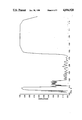
- FIG. 2 is a graph showing the reflectance characteristics of a SWP (Short Wave Pass) filter, which does not embody the invention of the present application, but which reflects light having a blue appearance.
- Distance above the horizontal axis represents reflectance.
- Horizontal distance away from the vertical axis represents wavelength in units of micrometers.
- FIG. 3 is a C.I.E. 1931 Chromaticity Diagram showing the reflection chromaticity of the FIG. 2 filter (and two modified versions thereof) as a function of incidence angle over the range from zero to eighty degrees.
- FIG. 4 is a graph (having the same axes as FIG. 2) showing the reflectance characteristics of a preferred embodiment of the inventive filter that reflects light having a blue appearance.
- FIG. 5 is a reflection chromaticity plot showing the reflection chromaticity of the FIG. 4 filter (and two modified versions thereof) as a function of incidence angle over the range from zero to eighty degrees.
- FIG. 6 is a graph (having the same axes as FIG. 2) showing the reflectance characteristics of another preferred embodiment of the inventive filter that reflects light having a blue appearance.
- FIG. 7 is a reflection chromaticity plot showing the measured reflection chromaticity of a filter with the FIG. 6 design as a function of incidence angle.
- FIG. 8 is a reflection chromaticity plot showing the chromaticity of an inventive filter for reflecting violet light (and two variations on such filter), as a function of incidence angle over the range from zero to eighty degrees.
- FIG. 9 is a reflection chromaticity plot showing the chromaticity of an inventive filter for reflecting orange light (and two variations on such filter), as a function of incidence angle over the range from zero to eighty degrees.
- FIG. 1 is an enlarged cross-sectional view of an SWP filter of the type that may embody the invention.
- Substrate 1 is preferably an optical filter glass, preferably of the type that absorbs UV radiation (radiation having wavelength less than 400 nm) and transmits approx. 25% of all visible light.
- UV-absorbing glass of any conventional type is suitable for use as substrate 1 in many applications, such as applications in which the filter is used as a sunglass lens.
- TAN-C Crown Glass manufactured by Schott Glass Technologies, Inc.
- the substrate on which the inventive coating is applied need not be absorptive of UV and partially absorptive of visible light. Alternatively, it could be transparent to either UV, or visible light, or to both. Also, where it is desired to use a non-absorptive substrate, a single thin-film layer of absorbing material may be coated on transparent glass to achieve the desired optical properties of the substrate.
- a number of quarter-wave layers (having reference numerals 2 through N+6) are successively coated on the surface of substrate 1, so that layers formed of material having low refractive index alternate with layers formed of material having high refractive index.
- the number of quarter-wave layers (each having optical thickness substantially equal to a desired quarter-wavelength) coated on the substrate will depend on the desired optical properties of the filter.
- the invention in its broadest scope is not limited to a class of filters having any specific number of layers. There may be an even number or odd number of layers.
- the layer immediately adjacent the substrate may be a member of the subset having high refractive index or may be a member of the subset having low refractive index.
- substrate 1 is glass having index of refraction equal to 1.52, the even layers (2, 4, 6 and so on) are composed of silicon dioxide (having an approximate index of refraction 1.44) and the odd layers (3, 5, 7 and so on) are composed of titanium dioxide (having an approximate index of refraction 2.25).
- the even-numbered coatings may be composed of titanium dioxide (having refractive index of 2.25) and the odd-numbered coatings may be composed of silicon dioxide (having refractive index of 1.44).
- oxide compounds could be substituted for these materials (i.e., TiO or TiO 2 O 3 may be substituted for TiO 2 ).
- each subset need not all have identical refractive index, or optical thickness equal to one quarter wavelength of a single selected electromagnetic wave.
- the refractive index and thickness of each layer is selected in a manner to be described below so that the filter has a reflectance spectrum having the following properties: a ripple over at least a first segment (or "region") of the visible spectrum, but no significant ripple over a second segment of the visible spectrum; and a partial second-order stopband region located so as to reduce the variation of the reflected visible light's color with incidence angle and so that the neutral color balance of the transmitted visible light is substantially independent of incidence angle.
- segment and “region” will be used interchangeably throughout this Specification, including in the claims, to denote any continuous wavelength range of the electromagnetic spectrum spanned by two distinct wavelengths, and to denote several of such ranges.
- the term “ripple” (or “rippled region”, or the like) will be used to describe a portion of a reflectance spectrum (such as the spectrum of FIG. 2, 3, or 4) that includes peaks and troughs with sufficiently large peaks (a large peak represents a large reflectance) so that an observer of reflected light from the filter having wavelength within the rippled region will observe a desired reflected color, but an observer of visible light transmitted from a real-world object through the filter will perceive true real-world colors.
- transmitted light having wavelengths in the non-rippled portion of the visible range together with transmitted light having wavelengths corresponding to the rippled region, will be perceived as having a neutral color balance.
- Regions in the visible reflectance spectrum that include ripples of sufficiently low amplitude do not contribute significantly to producing a desired aesthetic color to an observer viewing the filter. These regions will not be referred to as exhibiting a "significant ripple” or "a ripple” (or the like), and instead will be denoted as “non-rippled” regions (or the like).
- FIG. 2 is the reflectance curve characterizing an optical filter which does not embody the invention of the present application, but which reflects light having a blue appearance.
- This filter reflects substantially all (i.e. more than approximately 93 percent) near-infrared electromagnetic radiation in the segment of the spectrum above the wavelength 790 nm, and transmits substantially all light in the range from 505 nm to 700 nm. There is no ripple of significant amplitude in such 505-700 nm range.
- the reflectance curve does exhibit a ripple in the blue region from about 450 nm to about 505 nm.
- the FIG. 2 filter is designed so that its transmitted color balance is neutral. The eye of a viewer observing light transmitted through the FIG. 2 filter will not be very sensitive to the reflected components having low amplitude (the wavelength components corresponding to the ripple).
- the FIG. 2 filter includes a glass substrate having refractive index 1.52 and total transmission (as a function of wavelength) as listed in Table 1, and twenty-nine alternating layers of SiO 2 (with refractive index 1.44), and TiO 2 (with refractive index 2.25) supported by the substrate's surface.
- the total transmission is indicative of the amount of absorption in the substrate as a function of wavelength.
- the physical thickness and refractive index of each layer supported by the substrate is listed in Table 2:
- the layer immediately adjacent the substrate is identified as layer number 1, and the layer farthest from the substrate is identified as layer number 29.
- Layer 29 is intentionally much thicker than the other SiO 2 layers, so that it will be scratch insensitive, in the sense that minor scratches in layer 29 will not be apparent to a viewer of reflected or transmitted light.
- the twenty-nine layers comprise a double quarter-wave coating stack, with optimized layer thickness.
- the highly reflective region of the FIG. 2 filter above about 790 nm is denoted the "first order stopband.”
- a second order stopband would occur at twice the frequency (half the wavelength) of the first order stopband, if it were present, but is missing in the FIG. 2 filter, since the FIG. 2 filter's alternating high refractive index and low refractive index layers have approximately equal optical thickness.
- the highly reflective region from about 340 nm to 420 nm in FIG. 2 is the third order stopband (occurring at three times the frequency of the first order stopband).
- the numerals on curve C correspond to dominant wavelengths in micrometers.
- Each data point on curve E of FIG. 3 represents the reflection chromaticity of the FIG. 2 filter at an incidence angle in the set comprising 0°, 20°, 30°, 40°, 50°, 60°, 70°, and 80°. It is apparent from curve E that the reflected color changes from greenish-blue, to blue, and then to violet, as the filter is "tilted" while viewed in reflected light to cause the incidence angle to change from zero degrees to 80 degrees.
- Curve D in FIG. 3 represents the reflection chromaticity of a modified version of the FIG. 2 filter in which the thickness of each high refractive index layer is increased by five percent.
- Curve F in FIG. 3 represents the reflection chromaticity of a modified version the FIG. 2 filter in which the thickness of each high refractive index layer ("H" layer) is decreased by five percent.
- Comparison of curves E and F shows that reducing the thickness of each H layer in the curve E filter design, will moderately improve (i.e., reduce) the reflected color variation with incidence angle.
- FIG. 4 embodiment is an SWP filter, comprising a double stack of substantially quarter wave layers, designed to reflect light having a blue appearance.
- This filter is characterized by the reflectance curve shown in FIG. 4.
- the FIG. 4 filter reflects substantially all NIR radiation, and transmits substantially all visible radiation in the 580 nm-780 nm band. Although the reflectance in the 580-780 nm band is not perfectly flat (near zero), it exhibits no rippling of significant amplitude in that range.
- the FIG. 4 filter reflects substantially all NIR radiation, and transmits substantially all visible radiation in the 580 nm-780 nm band. Although the reflectance in the 580-780 nm band is not perfectly flat (near zero), it exhibits no rippling of significant amplitude in that range.
- FIG. 5 is another C.I.E. 1931 Chromaticity diagram.
- Curve I in FIG. 5 represents the reflection chromaticity of a modified version of the FIG. 4 filter in which the thickness of each high refractive index layer is increased by five percent.
- Curve H in FIG. 5 represents the reflection chromaticity of a modified version the FIG. 4 filter in which the thickness of each high refractive index layer ("H" layer) is decreased by five percent.
- the designs represented by curves H and I are clearly inferior to the FIG. 4 design (represented by curve G) in the sense that they exhibit greater reflected color variation with incidence angle than does the FIG. 4 design.
- FIG. 6 filter is an SWP filter designed to reflect light having a blue appearance.
- the FIG. 6 design is substantially the same as the FIG. 4 design, except in that it includes a partial second-order stopband (identified by reference character S) at about 560 nm.
- a partial second-order stopband is induced by detuning or decreasing the thickness of the high refractive index layers ("H" layers) of the top quarter wave stack of the FIG. 4 design by five percent, and decreasing the thickness of the H layers of the bottom quarter wave stack of the FIG. 4 design by three percent.
- H high refractive index layers
- the partial second-order stopband may be centered at any point in the range 520-580 nm, with a rippled region occurring in the range 420-500 nm.
- the amount of light reflected in the rippled regions and the partial second-order stopband of the FIG. 6 filter is sufficiently small (or occurs in the wavelength range below 450 nm, in which the human eye is relatively insensitive) so that the transmitted color balance will be substantially neutral.
- the FIG. 6 filter includes a glass substrate (with refractive index 1.52 and total transmission as listed in Table 1) and thirty-one layers of SiO 2 (with refractive index 1.44) and TiO 2 (with refractive index 2.25) supported by the substrate's surface.
- the physical thickness and refractive index of each layer is listed in Table 3:
- the layers are numbered in order of increasing distance from the substrate so that layer number 1 is the layer immediately adjacent to the substrate and layer number 31 is the outermost, scratch insensitive layer.
- FIG. 7 is a C.I.E. 1931 Chromaticity diagram showing reflection chromaticity as a function of incidence angle (in the range from 20 degrees to more than 60 degrees) of the thirty-one layer coating of Table 3 supported by a clear glass substrate. It is apparent that blue visible light reflected from this filter is substantially color invariant as the filter is "tilted” to cause the incidence angle to change from twelve degrees to over sixty degrees. This phenomenon occurs because with increasing incidence angle, the partial second-order stopband will shift into the range (420-500 nm) previously occupied by the rippled region at zero incidence angle.
- the inventive design technique thus includes the steps of varying the relative thickness of the H layers and low refractive index layers ("L" layers) in a quarter wave stack (or double quarter wave stack, or multiple quarter wave stack) to reduce reflected color variation with incidence angle.
- the reflected color variation is reduced sufficiently so that the dominant reflected color is substantially independent of incidence angle.
- the thickness of each H layer in either (or both) quarter wave stacks may be simultaneously increased (or decreased) by the same percentage relative to the correct L layer thicknesses in the stack.
- the invention applies equally well to the design of filters for reflecting visible radiation having any color (i.e., blue, orange, or violet).
- any color i.e., blue, orange, or violet.
- FIG. 8 is a C.I.E. 1931 Chromaticity diagram showing the reflection chromaticity (as a function of incidence angle in the range from zero to eighty degrees) for an SWP filter which reflects violet light.
- Curve T which represents this SWP filter, follows a path that moves from purple to pink in color.
- visible light reflected from the curve T filter is not substantially color invariant as the filter is "tilted" to cause the incidence angle to change from zero degrees to eighty degrees.
- Curve U in FIG. 8 represents the reflection chromaticity of a modified version of the curve T filter in which the thickness of each H layer is simultaneously increased by five percent.
- Curve V in FIG. 8 represents the reflection chromaticity of a modified version the curve T filter in which the thickness of each H layer is simultaneously decreased by five percent.
- the designs represented by curves T and V are clearly inferior to the curve U design in the sense that they exhibit greater reflected color variation with incidence angle than does the curve T design.
- Curve U remains in the purple region, and thus represents an embodiment of the invention.
- FIG. 9 is a C.I.E. 1931 Chromaticity diagram showing the reflection chromaticity (as a function of incidence angle in the range from zero to eighty degrees) for an SWP filter which reflects orange light.
- Curve L which represents this SWP filter, is a path from an intense reddish-orange to a less intense orange. Thus visible light reflected from the curve L filter is not substantially color invariant as the filter is "tilted" to cause the incidence angle to change from zero degrees to eighty degrees.
- Curve M in FIG. 9 represents the reflection chromaticity of a modified version of the curve L filter in which the thickness of each H layer is simultaneously increased by five percent.
- Curve N in FIG. 9 represents the reflection chromaticity of a modified version the curve L filter in which the thickness of each H layer is simultaneously decreased by five percent.
- the designs represented by curves L and N are clearly inferior to the curve M design in the sense that they exhibit greater reflected color variation with incidence angle than does the curve L design. Curve M remains in the orange region, and this represents an embodiment of the invention.
- each of the preferred embodiments of the invention is determined using an iterative optimization technique given the following constraints: the optical constants of the substrate and film materials are known; the desired reflectance spectrum is specified; then each layer thickness is found. To insure the filter is conveniently and repeatably manufactured, each layer's thickness must be within a specified tolerance of the optimum thickness. Therefore any small variations in each layer's thickness will not significantly alter the filter's reflectance curve.
- the layer farthest from the substrate should be sufficiently thick so as to be scratch insensitive (in the sense defined above).
- the inventive filter is preferably designed to be useful as a sunglass lens that will have a selected aesthetic appearance (in reflected light) to persons observing the wearer of the sunglasses.
- the substrate glass should be selected to be absorptive of ultra-violet (UV) electromagnetic radiation and to be partially absorptive of the visible wavelength band.
- UV ultra-violet
Abstract
Description
              TABLE 1
______________________________________
Wavelength (nanometers)
                  Total Transmission
______________________________________
360               1.0E-6
400               .0225
440               .03
480               .061
520               .100
560               .167
600               .206
640               .225
680               .241
700               .24
740               .188
780               .136
______________________________________
              TABLE 2
______________________________________
                           Physical Thickness
Layer Number
            Refractive Index
                           (micrometers)
______________________________________
1           1.44           .0122
2           2.25           .1134
3           1.44           .1757
4           2.25           .1089
5           1.44           .1531
6           2.25           .1047
7           1.44           .1623
8           2.25           .1024
9           1.44           .1590
10          2.25           .1044
11          1.44           .1545
12          2.25           .1073
13          1.44           .1544
14          2.25           .1086
15          1.44           .1590
16          2.25           .1103
17          1.44           .1691
18          2.25           .1210
19          1.44           .1899
20          2.25           .1249
21          1.44           .2018
22          2.25           .1177
23          1.44           .2048
24          2.25           .1299
25          1.44           .1930
26          2.25           .1146
27          1.44           .1931
28          2.25           .1124
29          1.44           .3161
______________________________________
              TABLE 3
______________________________________
                           Physical Thickness
Layer Number
            Refractive Index
                           (micrometers)
______________________________________
1           1.44           .0122
2           2.25           .1115
3           1.44           .1856
4           2.25           .1055
5           1.44           .1653
6           2.25           .1055
7           1.44           .1685
8           2.25           .1008
9           1.44           .1659
10          2.25           .1021
11          1.44           .1678
12          2.25           .1018
13          1.44           .1657
14          2.25           .1045
15          1.44           .1693
16          2.25           .1083
17          1.44           .1791
18          2.25           .1176
19          1.44           .1908
20          2.25           .1182
21          1.44           .1985
22          2.25           .1167
23          1.44           .1899
24          2.25           .1225
25          1.44           .1884
26          2.25           .1220
27          1.44           .2048
28          2.25           .1081
29          1.44           .1898
30          2.25           .1310
31          1.44           .3282
______________________________________
Claims (33)
Priority Applications (1)
| Application Number | Priority Date | Filing Date | Title |
|---|---|---|---|
| US07/238,095 US4896928A (en) | 1988-08-29 | 1988-08-29 | Chromatically invariant multilayer dielectric thin film coating |
Applications Claiming Priority (1)
| Application Number | Priority Date | Filing Date | Title |
|---|---|---|---|
| US07/238,095 US4896928A (en) | 1988-08-29 | 1988-08-29 | Chromatically invariant multilayer dielectric thin film coating |
Publications (1)
| Publication Number | Publication Date |
|---|---|
| US4896928A true US4896928A (en) | 1990-01-30 |
Family
ID=22896473
Family Applications (1)
| Application Number | Title | Priority Date | Filing Date |
|---|---|---|---|
| US07/238,095 Expired - Lifetime US4896928A (en) | 1988-08-29 | 1988-08-29 | Chromatically invariant multilayer dielectric thin film coating |
Country Status (1)
| Country | Link |
|---|---|
| US (1) | US4896928A (en) |
Cited By (67)
| Publication number | Priority date | Publication date | Assignee | Title |
|---|---|---|---|---|
| WO1991008106A1 (en) * | 1989-12-01 | 1991-06-13 | Viratec Thin Films, Inc. | Antireflection layer system with integral uv blocking properties |
| US5138219A (en) * | 1989-07-19 | 1992-08-11 | General Electric Company | Optical interference coating and lamps using same |
| US5154512A (en) * | 1990-04-10 | 1992-10-13 | Luxtron Corporation | Non-contact techniques for measuring temperature or radiation-heated objects |
| EP0540215A2 (en) * | 1991-10-29 | 1993-05-05 | Minnesota Mining And Manufacturing Company | Polymeric minus filter |
| US5310260A (en) * | 1990-04-10 | 1994-05-10 | Luxtron Corporation | Non-contact optical techniques for measuring surface conditions |
| US5348805A (en) * | 1990-07-05 | 1994-09-20 | Saint-Gobain Vitrage International | Formation of a layer of aluminum and tin or titanium oxides on a glass substrate |
| EP0725286A1 (en) * | 1994-11-14 | 1996-08-07 | Optical Coating Laboratory, Inc. | Optical filter with neutral reflectance for visual signalling mirror |
| US5574517A (en) * | 1994-12-21 | 1996-11-12 | Top One Optic Technology Inc. | Aid for color vision deficiencies |
| US5625492A (en) * | 1992-09-18 | 1997-04-29 | Leica Mikroskopie Und Systeme Gmbh | Color compensation filter |
| US5750265A (en) * | 1996-01-11 | 1998-05-12 | Libbey-Owens-Ford Co. | Coated glass article having a pyrolytic solar control coating |
| US5769540A (en) * | 1990-04-10 | 1998-06-23 | Luxtron Corporation | Non-contact optical techniques for measuring surface conditions |
| US5811191A (en) * | 1994-12-27 | 1998-09-22 | Ppg Industries, Inc. | Multilayer antireflective coating with a graded base layer |
| US5966240A (en) * | 1997-11-21 | 1999-10-12 | Coherent, Inc. | Laser blocking filter with neutral transmission color |
| WO2001004669A1 (en) * | 1999-07-12 | 2001-01-18 | Schott Glas | Narrow-band optical interference filter |
| EP1115568A1 (en) * | 1998-08-31 | 2001-07-18 | Corning Incorporated | Coated ultraviolet absorbing glass |
| US6391400B1 (en) | 1998-04-08 | 2002-05-21 | Thomas A. Russell | Thermal control films suitable for use in glazing |
| US20020154387A1 (en) * | 2001-04-20 | 2002-10-24 | Kenji Mori | Gain equalizer, collimator with gain equalizer and method of manufacturing gain equalizer |
| EP1330676A1 (en) * | 2000-10-30 | 2003-07-30 | Sola International, Inc. | Wide field spherical lenses and protective eyewear |
| US20030228472A1 (en) * | 2002-04-29 | 2003-12-11 | Hoffman Wayne L. | Coatings having low emissivity and low solar reflectance |
| US6678100B1 (en) | 2003-03-20 | 2004-01-13 | Pacific Beach, Inc. | Dual complementary two-color optics which enables a user to see true neutral color |
| US20040016202A1 (en) * | 2002-05-16 | 2004-01-29 | Hoffman Wayne L. | High shading performance coatings |
| US20040071985A1 (en) * | 2002-07-31 | 2004-04-15 | Krisko Annette J. | Temperable high shading performance coatings |
| WO2004079278A1 (en) * | 2003-03-06 | 2004-09-16 | Ecole Polytechnique Federale De Lausanne (Epfl) | Glazing |
| US20050094095A1 (en) * | 2003-11-04 | 2005-05-05 | Marason Thomas S. | Dual complementary two-color optics which enables a user to see true neutral color, with improved shading design and shadow detail |
| US20050224703A1 (en) * | 2002-05-21 | 2005-10-13 | 3M Innovative Properties Company | Photopic detector system and filter therefor |
| WO2005111128A2 (en) * | 2004-05-03 | 2005-11-24 | Flint Ink Corporation | Ink for excimer curing |
| US7138156B1 (en) * | 2000-09-26 | 2006-11-21 | Myrick Michael L | Filter design algorithm for multi-variate optical computing |
| US20090116114A1 (en) * | 2007-11-02 | 2009-05-07 | Light Prescriptions Innovators, Llc | Wideband dichroic-filter design for LED-phosphor beam-combining |
| US20100260929A1 (en) * | 2007-09-26 | 2010-10-14 | Fyson John R | Method of making a colour filter array |
| US20110128616A1 (en) * | 2007-08-12 | 2011-06-02 | Toyota Motor Engineering & Manufacturing North America, Inc. | Omnidirectional reflector |
| US20110134515A1 (en) * | 2007-08-12 | 2011-06-09 | Toyota Motor Engineering & Manufacturing North America, Inc. | Omnidirectional uv-ir reflector |
| WO2011146288A1 (en) * | 2010-05-21 | 2011-11-24 | 3M Innovative Properties Company | Partially reflecting multilayer optical films with reduced color |
| JP2011257755A (en) * | 2010-06-04 | 2011-12-22 | Toyota Motor Engineering & Manufacturing North America Inc | Omnidirectional reflector |
| US20120128314A1 (en) * | 2009-10-09 | 2012-05-24 | Xiaosong Wu | D1451 methods for formulating radiation curable supercoatings for optical fiber |
| US20140335330A1 (en) * | 2013-05-07 | 2014-11-13 | Corning Incorporated | Low-Color Scratch-Resistant Articles with a Multilayer Optical Film |
| US20150043058A1 (en) * | 2012-01-11 | 2015-02-12 | Konica Minolta, Inc. | Infrared shielding film |
| US9115864B2 (en) | 2013-08-21 | 2015-08-25 | General Electric Company | Optical interference filters, and filament tubes and lamps provided therewith |
| US20150249424A1 (en) * | 2012-09-20 | 2015-09-03 | Swissinso Sa | Laminated glazing with coloured reflection and high solar transmittance suitable for solar energy systems |
| JP2016538597A (en) * | 2013-11-27 | 2016-12-08 | スリーエム イノベイティブ プロパティズ カンパニー | Blue edge filter optical lens |
| EP3112910A1 (en) | 2015-06-29 | 2017-01-04 | ESSILOR INTERNATIONAL (Compagnie Générale d'Optique) | Optical filter |
| US20170075144A1 (en) * | 2013-11-26 | 2017-03-16 | Hoya Lens Thailand Ltd. | Spectacle lens |
| US9612369B2 (en) | 2007-08-12 | 2017-04-04 | Toyota Motor Engineering & Manufacturing North America, Inc. | Red omnidirectional structural color made from metal and dielectric layers |
| US9658375B2 (en) | 2012-08-10 | 2017-05-23 | Toyota Motor Engineering & Manufacturing North America, Inc. | Omnidirectional high chroma red structural color with combination metal absorber and dielectric absorber layers |
| CN106707391A (en) * | 2016-12-05 | 2017-05-24 | 云南北方驰宏光电有限公司 | Double-bandpass cut-off type filtering film, optical filter and preparation method of optical filter |
| US9664832B2 (en) | 2012-08-10 | 2017-05-30 | Toyota Motor Engineering & Manufacturing North America, Inc. | Omnidirectional high chroma red structural color with combination semiconductor absorber and dielectric absorber layers |
| US9678260B2 (en) | 2012-08-10 | 2017-06-13 | Toyota Motor Engineering & Manufacturing North America, Inc. | Omnidirectional high chroma red structural color with semiconductor absorber layer |
| US9739917B2 (en) | 2007-08-12 | 2017-08-22 | Toyota Motor Engineering & Manufacturing North America, Inc. | Red omnidirectional structural color made from metal and dielectric layers |
| US9810824B2 (en) | 2015-01-28 | 2017-11-07 | Toyota Motor Engineering & Manufacturing North America, Inc. | Omnidirectional high chroma red structural colors |
| CN107403845A (en) * | 2016-05-19 | 2017-11-28 | 拉碧斯半导体株式会社 | The manufacture method of semiconductor device and semiconductor device |
| US10048415B2 (en) | 2007-08-12 | 2018-08-14 | Toyota Motor Engineering & Manufacturing North America, Inc. | Non-dichroic omnidirectional structural color |
| US10222524B2 (en) | 2015-10-13 | 2019-03-05 | Vision Ease, Lp | Optical filter with selective transmittance and reflectance |
| US10317701B2 (en) | 2015-03-18 | 2019-06-11 | Vision Ease, Lp | Crazing resistant coating and method thereof |
| US10613353B2 (en) * | 2017-05-09 | 2020-04-07 | Onelensolution Optical Technology Sdn Bhd | Optical lenses |
| US10690823B2 (en) | 2007-08-12 | 2020-06-23 | Toyota Motor Corporation | Omnidirectional structural color made from metal and dielectric layers |
| US10788608B2 (en) | 2007-08-12 | 2020-09-29 | Toyota Jidosha Kabushiki Kaisha | Non-color shifting multilayer structures |
| US10845505B2 (en) | 2015-03-09 | 2020-11-24 | Vision Ease, Lp | Anti-static, anti-reflective coating |
| US10866434B2 (en) | 2015-09-29 | 2020-12-15 | Vision Ease, Lp | UV and high energy visible absorbing ophthalmic lenses |
| US10870740B2 (en) | 2007-08-12 | 2020-12-22 | Toyota Jidosha Kabushiki Kaisha | Non-color shifting multilayer structures and protective coatings thereon |
| US10948629B2 (en) | 2018-08-17 | 2021-03-16 | Corning Incorporated | Inorganic oxide articles with thin, durable anti-reflective structures |
| US10995404B2 (en) | 2014-08-01 | 2021-05-04 | Corning Incorporated | Scratch-resistant materials and articles including the same |
| US11002885B2 (en) | 2015-09-14 | 2021-05-11 | Corning Incorporated | Scratch-resistant anti-reflective articles |
| US11086053B2 (en) | 2014-04-01 | 2021-08-10 | Toyota Motor Engineering & Manufacturing North America, Inc. | Non-color shifting multilayer structures |
| US11231526B2 (en) | 2013-05-07 | 2022-01-25 | Corning Incorporated | Low-color scratch-resistant articles with a multilayer optical film |
| US11267973B2 (en) | 2014-05-12 | 2022-03-08 | Corning Incorporated | Durable anti-reflective articles |
| US11667565B2 (en) | 2013-05-07 | 2023-06-06 | Corning Incorporated | Scratch-resistant laminates with retained optical properties |
| RU2799894C1 (en) * | 2022-04-21 | 2023-07-13 | Российская Федерация от имени которой выступает Министерство промышленности и торговли Российской Федерации (Минпромторг России) | Optical interference blocking filter |
| US11745473B2 (en) | 2012-09-20 | 2023-09-05 | Kromatix SA | Laminated glazing with coloured reflection and high solar transmittance, and solar energy systems employing the same |
Citations (6)
| Publication number | Priority date | Publication date | Assignee | Title |
|---|---|---|---|---|
| US3990784A (en) * | 1974-06-05 | 1976-11-09 | Optical Coating Laboratory, Inc. | Coated architectural glass system and method |
| US4045125A (en) * | 1974-06-27 | 1977-08-30 | Etat Francias | Band filters for use in protective glasses |
| US4047805A (en) * | 1973-02-14 | 1977-09-13 | Canon Kabushiki Kaisha | Ripple-free dichroic mirrors |
| US4229666A (en) * | 1978-09-27 | 1980-10-21 | Gte Products Corporation | Audio detector circuit |
| US4536063A (en) * | 1982-12-14 | 1985-08-20 | Rockwell International Corporation | Transmissive phase retarder |
| US4793669A (en) * | 1987-09-11 | 1988-12-27 | Coherent, Inc. | Multilayer optical filter for producing colored reflected light and neutral transmission |
-
1988
- 1988-08-29 US US07/238,095 patent/US4896928A/en not_active Expired - Lifetime
Patent Citations (6)
| Publication number | Priority date | Publication date | Assignee | Title |
|---|---|---|---|---|
| US4047805A (en) * | 1973-02-14 | 1977-09-13 | Canon Kabushiki Kaisha | Ripple-free dichroic mirrors |
| US3990784A (en) * | 1974-06-05 | 1976-11-09 | Optical Coating Laboratory, Inc. | Coated architectural glass system and method |
| US4045125A (en) * | 1974-06-27 | 1977-08-30 | Etat Francias | Band filters for use in protective glasses |
| US4229666A (en) * | 1978-09-27 | 1980-10-21 | Gte Products Corporation | Audio detector circuit |
| US4536063A (en) * | 1982-12-14 | 1985-08-20 | Rockwell International Corporation | Transmissive phase retarder |
| US4793669A (en) * | 1987-09-11 | 1988-12-27 | Coherent, Inc. | Multilayer optical filter for producing colored reflected light and neutral transmission |
Non-Patent Citations (12)
| Title |
|---|
| "Electric Field Distribution and the Reduction of Laser Damage in Multilayers", O. Arnon and P. Baumeister, Applied Optics, vol. 19, No. 11, Jun. 1980. |
| "Nonpolarizing Edge Filters", Alfred Thelen, J. of the Optical Society of America, vol. 71, No. 3, Mar. 1981 (pp. 309-314). |
| "Optical Coating Design with Reduced Electric Field Intensity", Joseph H. Apfel, Applied Optics, vol. 16, No. 7, Jul. 1977 (pp. 1880-1885). |
| "Optical Interference Coating Technology", Lecture Notes of Philip Baumeister, pp. 2-92, 2-93, and 6-48 thru 6-51 (Dec. 1985). |
| "The Transmission and Degree of Polarization of Quarter-Waves Stacks at Non-Normal Incidence", Philip Baumeister, Optica Acta, vol. 8, No. 2, Apr. 1961 (pp. 105-119). |
| Baumeister; "Design of Multilayer Filters by Successive Approximations"; Journal of the Optical Society of America, vol. 48, No. 12; Dec. 1958; pp. 955-958. |
| Baumeister; Design of Multilayer Filters by Successive Approximations ; Journal of the Optical Society of America, vol. 48, No. 12; Dec. 1958; pp. 955 958. * |
| Electric Field Distribution and the Reduction of Laser Damage in Multilayers , O. Arnon and P. Baumeister, Applied Optics, vol. 19, No. 11, Jun. 1980. * |
| Nonpolarizing Edge Filters , Alfred Thelen, J. of the Optical Society of America, vol. 71, No. 3, Mar. 1981 (pp. 309 314). * |
| Optical Coating Design with Reduced Electric Field Intensity , Joseph H. Apfel, Applied Optics, vol. 16, No. 7, Jul. 1977 (pp. 1880 1885). * |
| Optical Interference Coating Technology , Lecture Notes of Philip Baumeister, pp. 2 92, 2 93, and 6 48 thru 6 51 (Dec. 1985). * |
| The Transmission and Degree of Polarization of Quarter Waves Stacks at Non Normal Incidence , Philip Baumeister, Optica Acta, vol. 8, No. 2, Apr. 1961 (pp. 105 119). * |
Cited By (116)
| Publication number | Priority date | Publication date | Assignee | Title |
|---|---|---|---|---|
| US5138219A (en) * | 1989-07-19 | 1992-08-11 | General Electric Company | Optical interference coating and lamps using same |
| US5982078A (en) * | 1989-07-19 | 1999-11-09 | General Electric Company | Optical interference coatings and lamps using same |
| WO1991008106A1 (en) * | 1989-12-01 | 1991-06-13 | Viratec Thin Films, Inc. | Antireflection layer system with integral uv blocking properties |
| US5490728A (en) * | 1990-04-10 | 1996-02-13 | Luxtron Corporation | Non-contact optical techniques for measuring surface conditions |
| US5154512A (en) * | 1990-04-10 | 1992-10-13 | Luxtron Corporation | Non-contact techniques for measuring temperature or radiation-heated objects |
| US5769540A (en) * | 1990-04-10 | 1998-06-23 | Luxtron Corporation | Non-contact optical techniques for measuring surface conditions |
| US5310260A (en) * | 1990-04-10 | 1994-05-10 | Luxtron Corporation | Non-contact optical techniques for measuring surface conditions |
| US5348805A (en) * | 1990-07-05 | 1994-09-20 | Saint-Gobain Vitrage International | Formation of a layer of aluminum and tin or titanium oxides on a glass substrate |
| EP0540215A2 (en) * | 1991-10-29 | 1993-05-05 | Minnesota Mining And Manufacturing Company | Polymeric minus filter |
| US5238738A (en) * | 1991-10-29 | 1993-08-24 | Minnesota Mining And Manufacturing Company | Polymeric minus filter |
| EP0540215A3 (en) * | 1991-10-29 | 1993-06-23 | Minnesota Mining And Manufacturing Company | Polymeric minus filter |
| US5625492A (en) * | 1992-09-18 | 1997-04-29 | Leica Mikroskopie Und Systeme Gmbh | Color compensation filter |
| EP0725286A1 (en) * | 1994-11-14 | 1996-08-07 | Optical Coating Laboratory, Inc. | Optical filter with neutral reflectance for visual signalling mirror |
| US5574517A (en) * | 1994-12-21 | 1996-11-12 | Top One Optic Technology Inc. | Aid for color vision deficiencies |
| US5811191A (en) * | 1994-12-27 | 1998-09-22 | Ppg Industries, Inc. | Multilayer antireflective coating with a graded base layer |
| US5750265A (en) * | 1996-01-11 | 1998-05-12 | Libbey-Owens-Ford Co. | Coated glass article having a pyrolytic solar control coating |
| US5897957A (en) * | 1996-01-11 | 1999-04-27 | Libbey-Owens-Ford Co. | Coated glass article having a solar control coating |
| US5966240A (en) * | 1997-11-21 | 1999-10-12 | Coherent, Inc. | Laser blocking filter with neutral transmission color |
| US6391400B1 (en) | 1998-04-08 | 2002-05-21 | Thomas A. Russell | Thermal control films suitable for use in glazing |
| EP1115568A1 (en) * | 1998-08-31 | 2001-07-18 | Corning Incorporated | Coated ultraviolet absorbing glass |
| EP1115568A4 (en) * | 1998-08-31 | 2005-06-29 | Corning Inc | Coated ultraviolet absorbing glass |
| WO2001004669A1 (en) * | 1999-07-12 | 2001-01-18 | Schott Glas | Narrow-band optical interference filter |
| US7138156B1 (en) * | 2000-09-26 | 2006-11-21 | Myrick Michael L | Filter design algorithm for multi-variate optical computing |
| EP1330676A1 (en) * | 2000-10-30 | 2003-07-30 | Sola International, Inc. | Wide field spherical lenses and protective eyewear |
| EP1330676A4 (en) * | 2000-10-30 | 2006-10-25 | Sola International Inc | Wide field spherical lenses and protective eyewear |
| US20020154387A1 (en) * | 2001-04-20 | 2002-10-24 | Kenji Mori | Gain equalizer, collimator with gain equalizer and method of manufacturing gain equalizer |
| US7758915B2 (en) | 2002-04-29 | 2010-07-20 | Cardinal Cg Company | Low-emissivity coating having low solar reflectance |
| US20060222763A1 (en) * | 2002-04-29 | 2006-10-05 | Hoffman Wayne L | Coatings having low emissivity and low solar reflectance |
| US7670641B2 (en) | 2002-04-29 | 2010-03-02 | Cardinal Cg Company | Coatings having low emissivity and low solar reflectance |
| US20040028955A1 (en) * | 2002-04-29 | 2004-02-12 | Hoffman Wayne L. | Low-emissivity coating having low solar reflectance |
| US20030228472A1 (en) * | 2002-04-29 | 2003-12-11 | Hoffman Wayne L. | Coatings having low emissivity and low solar reflectance |
| US7063893B2 (en) | 2002-04-29 | 2006-06-20 | Cardinal Cg Company | Low-emissivity coating having low solar reflectance |
| US7067195B2 (en) | 2002-04-29 | 2006-06-27 | Cardinal Cg Company | Coatings having low emissivity and low solar reflectance |
| US7687149B2 (en) | 2002-05-16 | 2010-03-30 | Cardinal Cg Company | High shading performance coatings |
| US20070009745A1 (en) * | 2002-05-16 | 2007-01-11 | Cardinal Cg Company | High shading performance coatings |
| US20040016202A1 (en) * | 2002-05-16 | 2004-01-29 | Hoffman Wayne L. | High shading performance coatings |
| US7122252B2 (en) | 2002-05-16 | 2006-10-17 | Cardinal Cg Company | High shading performance coatings |
| US20050224703A1 (en) * | 2002-05-21 | 2005-10-13 | 3M Innovative Properties Company | Photopic detector system and filter therefor |
| US7075056B2 (en) | 2002-05-21 | 2006-07-11 | 3M Innovative Properties Company | Photopic detector system having a filter with an interference element, an absorptive element and an absorber or reflector |
| US7138182B2 (en) | 2002-07-31 | 2006-11-21 | Cardinal Cg Compay | Temperable high shading performance coatings |
| US20040071985A1 (en) * | 2002-07-31 | 2004-04-15 | Krisko Annette J. | Temperable high shading performance coatings |
| US20070042114A1 (en) * | 2002-07-31 | 2007-02-22 | Cardinal Cg Company | Temperable high shading performance coatings |
| US7534497B2 (en) | 2002-07-31 | 2009-05-19 | Cardinal Cg Company | Temperable high shading performance coatings |
| WO2004079278A1 (en) * | 2003-03-06 | 2004-09-16 | Ecole Polytechnique Federale De Lausanne (Epfl) | Glazing |
| US6678100B1 (en) | 2003-03-20 | 2004-01-13 | Pacific Beach, Inc. | Dual complementary two-color optics which enables a user to see true neutral color |
| US6932472B2 (en) | 2003-11-04 | 2005-08-23 | Pacific Beach, Inc. | Dual complementary two-color optics which enables a user to see true neutral color, with improved shading design and shadow detail |
| US20050094095A1 (en) * | 2003-11-04 | 2005-05-05 | Marason Thomas S. | Dual complementary two-color optics which enables a user to see true neutral color, with improved shading design and shadow detail |
| WO2005111128A3 (en) * | 2004-05-03 | 2006-10-19 | Flint Ink Corp | Ink for excimer curing |
| WO2005111128A2 (en) * | 2004-05-03 | 2005-11-24 | Flint Ink Corporation | Ink for excimer curing |
| US11796724B2 (en) | 2007-08-12 | 2023-10-24 | Toyota Motor Corporation | Omnidirectional structural color made from metal and dielectric layers |
| US10690823B2 (en) | 2007-08-12 | 2020-06-23 | Toyota Motor Corporation | Omnidirectional structural color made from metal and dielectric layers |
| US9612369B2 (en) | 2007-08-12 | 2017-04-04 | Toyota Motor Engineering & Manufacturing North America, Inc. | Red omnidirectional structural color made from metal and dielectric layers |
| US20110128616A1 (en) * | 2007-08-12 | 2011-06-02 | Toyota Motor Engineering & Manufacturing North America, Inc. | Omnidirectional reflector |
| US20110134515A1 (en) * | 2007-08-12 | 2011-06-09 | Toyota Motor Engineering & Manufacturing North America, Inc. | Omnidirectional uv-ir reflector |
| US9229140B2 (en) | 2007-08-12 | 2016-01-05 | Toyota Motor Engineering & Manufacturing North America, Inc. | Omnidirectional UV-IR reflector |
| US10870740B2 (en) | 2007-08-12 | 2020-12-22 | Toyota Jidosha Kabushiki Kaisha | Non-color shifting multilayer structures and protective coatings thereon |
| US9739917B2 (en) | 2007-08-12 | 2017-08-22 | Toyota Motor Engineering & Manufacturing North America, Inc. | Red omnidirectional structural color made from metal and dielectric layers |
| US10788608B2 (en) | 2007-08-12 | 2020-09-29 | Toyota Jidosha Kabushiki Kaisha | Non-color shifting multilayer structures |
| US9063291B2 (en) * | 2007-08-12 | 2015-06-23 | Toyota Motor Engineering & Manufacturing North America, Inc. | Omnidirectional reflector |
| US10048415B2 (en) | 2007-08-12 | 2018-08-14 | Toyota Motor Engineering & Manufacturing North America, Inc. | Non-dichroic omnidirectional structural color |
| US20100260929A1 (en) * | 2007-09-26 | 2010-10-14 | Fyson John R | Method of making a colour filter array |
| US20090116114A1 (en) * | 2007-11-02 | 2009-05-07 | Light Prescriptions Innovators, Llc | Wideband dichroic-filter design for LED-phosphor beam-combining |
| US7859754B2 (en) * | 2007-11-02 | 2010-12-28 | Light Prescriptions Innovators, Llc | Wideband dichroic-filter design for LED-phosphor beam-combining |
| US20120128314A1 (en) * | 2009-10-09 | 2012-05-24 | Xiaosong Wu | D1451 methods for formulating radiation curable supercoatings for optical fiber |
| JP2013526730A (en) * | 2010-05-21 | 2013-06-24 | スリーエム イノベイティブ プロパティズ カンパニー | Color-reducing partially reflective multilayer optical film |
| CN102906605B (en) * | 2010-05-21 | 2016-02-03 | 3M创新有限公司 | There is the partially reflective multi-layer optical film of the colour of reduction |
| US9488766B2 (en) | 2010-05-21 | 2016-11-08 | 3M Innovative Properties Company | Partially reflecting multilayer optical films with reduced color |
| WO2011146288A1 (en) * | 2010-05-21 | 2011-11-24 | 3M Innovative Properties Company | Partially reflecting multilayer optical films with reduced color |
| US9188790B2 (en) | 2010-05-21 | 2015-11-17 | 3M Innovative Properties Company | Partially reflecting multilayer optical films with reduced color |
| CN102906605A (en) * | 2010-05-21 | 2013-01-30 | 3M创新有限公司 | Partially reflecting multilayer optical films with reduced color |
| JP2011257755A (en) * | 2010-06-04 | 2011-12-22 | Toyota Motor Engineering & Manufacturing North America Inc | Omnidirectional reflector |
| US20150043058A1 (en) * | 2012-01-11 | 2015-02-12 | Konica Minolta, Inc. | Infrared shielding film |
| US9588268B2 (en) * | 2012-01-11 | 2017-03-07 | Konica Minolta, Inc. | Infrared shielding film |
| US9664832B2 (en) | 2012-08-10 | 2017-05-30 | Toyota Motor Engineering & Manufacturing North America, Inc. | Omnidirectional high chroma red structural color with combination semiconductor absorber and dielectric absorber layers |
| US9678260B2 (en) | 2012-08-10 | 2017-06-13 | Toyota Motor Engineering & Manufacturing North America, Inc. | Omnidirectional high chroma red structural color with semiconductor absorber layer |
| US9658375B2 (en) | 2012-08-10 | 2017-05-23 | Toyota Motor Engineering & Manufacturing North America, Inc. | Omnidirectional high chroma red structural color with combination metal absorber and dielectric absorber layers |
| US11745473B2 (en) | 2012-09-20 | 2023-09-05 | Kromatix SA | Laminated glazing with coloured reflection and high solar transmittance, and solar energy systems employing the same |
| US20150249424A1 (en) * | 2012-09-20 | 2015-09-03 | Swissinso Sa | Laminated glazing with coloured reflection and high solar transmittance suitable for solar energy systems |
| US10953635B2 (en) | 2012-09-20 | 2021-03-23 | Swissinso Sa | Laminated glazing with coloured reflection and high solar transmittance suitable for solar energy systems |
| US11231526B2 (en) | 2013-05-07 | 2022-01-25 | Corning Incorporated | Low-color scratch-resistant articles with a multilayer optical film |
| US11667565B2 (en) | 2013-05-07 | 2023-06-06 | Corning Incorporated | Scratch-resistant laminates with retained optical properties |
| US11714213B2 (en) | 2013-05-07 | 2023-08-01 | Corning Incorporated | Low-color scratch-resistant articles with a multilayer optical film |
| US20140335330A1 (en) * | 2013-05-07 | 2014-11-13 | Corning Incorporated | Low-Color Scratch-Resistant Articles with a Multilayer Optical Film |
| US9359261B2 (en) * | 2013-05-07 | 2016-06-07 | Corning Incorporated | Low-color scratch-resistant articles with a multilayer optical film |
| US9115864B2 (en) | 2013-08-21 | 2015-08-25 | General Electric Company | Optical interference filters, and filament tubes and lamps provided therewith |
| US10718961B2 (en) * | 2013-11-26 | 2020-07-21 | Hoya Lens Thailand Ltd. | Spectacle lens |
| US20170075144A1 (en) * | 2013-11-26 | 2017-03-16 | Hoya Lens Thailand Ltd. | Spectacle lens |
| JP2016538597A (en) * | 2013-11-27 | 2016-12-08 | スリーエム イノベイティブ プロパティズ カンパニー | Blue edge filter optical lens |
| US10962806B2 (en) | 2013-11-27 | 2021-03-30 | 3M Innovative Properties Company | Blue edge filter optical lens |
| US11086053B2 (en) | 2014-04-01 | 2021-08-10 | Toyota Motor Engineering & Manufacturing North America, Inc. | Non-color shifting multilayer structures |
| US11726239B2 (en) | 2014-04-01 | 2023-08-15 | Toyota Motor Engineering & Manufacturing North America, Inc. | Non-color shifting multilayer structures |
| US11267973B2 (en) | 2014-05-12 | 2022-03-08 | Corning Incorporated | Durable anti-reflective articles |
| US10995404B2 (en) | 2014-08-01 | 2021-05-04 | Corning Incorporated | Scratch-resistant materials and articles including the same |
| US9810824B2 (en) | 2015-01-28 | 2017-11-07 | Toyota Motor Engineering & Manufacturing North America, Inc. | Omnidirectional high chroma red structural colors |
| US10845505B2 (en) | 2015-03-09 | 2020-11-24 | Vision Ease, Lp | Anti-static, anti-reflective coating |
| US10317701B2 (en) | 2015-03-18 | 2019-06-11 | Vision Ease, Lp | Crazing resistant coating and method thereof |
| US11112620B2 (en) | 2015-03-18 | 2021-09-07 | Vision Ease, Lp | Crazing resistant coating and method thereof |
| EP3112910A1 (en) | 2015-06-29 | 2017-01-04 | ESSILOR INTERNATIONAL (Compagnie Générale d'Optique) | Optical filter |
| WO2017001410A1 (en) | 2015-06-29 | 2017-01-05 | Essilor International (Compagnie Générale d'Optique) | Optical filter |
| CN107735701A (en) * | 2015-06-29 | 2018-02-23 | 埃西勒国际通用光学公司 | Optical filter |
| US20180107026A1 (en) * | 2015-06-29 | 2018-04-19 | Essilor International (Compagnie Genrale D'optique) | Optical filter |
| US11002885B2 (en) | 2015-09-14 | 2021-05-11 | Corning Incorporated | Scratch-resistant anti-reflective articles |
| US11698475B2 (en) | 2015-09-14 | 2023-07-11 | Corning Incorporated | Scratch-resistant anti-reflective articles |
| US10866434B2 (en) | 2015-09-29 | 2020-12-15 | Vision Ease, Lp | UV and high energy visible absorbing ophthalmic lenses |
| US11442293B2 (en) | 2015-09-29 | 2022-09-13 | Hoya Optical Labs Of America, Inc. | UV and high energy visible absorbing ophthalmic lenses |
| US10222524B2 (en) | 2015-10-13 | 2019-03-05 | Vision Ease, Lp | Optical filter with selective transmittance and reflectance |
| US10732334B2 (en) | 2015-10-13 | 2020-08-04 | Vision Ease, Lp | Optical filter with selective transmittance and reflectance |
| CN107403845A (en) * | 2016-05-19 | 2017-11-28 | 拉碧斯半导体株式会社 | The manufacture method of semiconductor device and semiconductor device |
| CN107403845B (en) * | 2016-05-19 | 2021-07-23 | 拉碧斯半导体株式会社 | Semiconductor device and method for manufacturing semiconductor device |
| CN106707391A (en) * | 2016-12-05 | 2017-05-24 | 云南北方驰宏光电有限公司 | Double-bandpass cut-off type filtering film, optical filter and preparation method of optical filter |
| CN106707391B (en) * | 2016-12-05 | 2019-04-05 | 云南北方驰宏光电有限公司 | Dual band pass cut-off type composite filter film, optical filter and preparation method thereof |
| US10613353B2 (en) * | 2017-05-09 | 2020-04-07 | Onelensolution Optical Technology Sdn Bhd | Optical lenses |
| US11567237B2 (en) | 2018-08-17 | 2023-01-31 | Corning Incorporated | Inorganic oxide articles with thin, durable anti-reflective structures |
| US10948629B2 (en) | 2018-08-17 | 2021-03-16 | Corning Incorporated | Inorganic oxide articles with thin, durable anti-reflective structures |
| US11906699B2 (en) | 2018-08-17 | 2024-02-20 | Corning Incorporated | Inorganic oxide articles with thin, durable anti reflective structures |
| RU2799894C1 (en) * | 2022-04-21 | 2023-07-13 | Российская Федерация от имени которой выступает Министерство промышленности и торговли Российской Федерации (Минпромторг России) | Optical interference blocking filter |
Similar Documents
| Publication | Publication Date | Title |
|---|---|---|
| US4896928A (en) | Chromatically invariant multilayer dielectric thin film coating | |
| US4793669A (en) | Multilayer optical filter for producing colored reflected light and neutral transmission | |
| USRE33729E (en) | Multilayer optical filter for producing colored reflected light and neutral transmission | |
| US5400174A (en) | Optical notch or minus filter | |
| US7633681B2 (en) | Multilayer interference filter for photochromic lenses | |
| EP0772572B1 (en) | Light-absorbing and anti-reflective coating for sunglasses | |
| US3679291A (en) | Filter with neutral transmitting multilayer coating having asymmetric reflectance | |
| US5054902A (en) | Light control with color enhancement | |
| US8425035B2 (en) | Spectacle lens with color-neutral anti-reflection coating and method of making the same | |
| EP0565703B1 (en) | Optical interference coating comprising interleaved thin-film stacks | |
| CA2146696C (en) | Optical filter arrangement | |
| US4756602A (en) | Narrowband optical filter with partitioned cavity | |
| CN1979230B (en) | Dielectric multilayer filter | |
| CA2220291C (en) | Multilayer thin film dielectric bandpass filter | |
| US6231992B1 (en) | Partial reflector | |
| US11561416B2 (en) | Ophthalmic tinted glass | |
| CN111108430B (en) | Optical lens for correcting colour vision | |
| KR20150107801A (en) | Filters to enhance color discrimination for color vision deficient individuals | |
| JP2004526995A (en) | Multi-layer thin film optical filter construction | |
| US4802755A (en) | Dual purpose sunglass lens having gold appearance and method of manufacture | |
| US6916095B2 (en) | Lenses having chromatic effect | |
| US6859323B1 (en) | Dichroic neutral density optical filter | |
| EP3514584A1 (en) | Angle of incidence restriction for optical filters | |
| US20220026613A1 (en) | Wire grid polarizer reflection control | |
| US20040036973A1 (en) | Multi-layer interference filter having colored reflectance and substantially uniform transmittance and methods of manufacturing the same |
Legal Events
| Date | Code | Title | Description |
|---|---|---|---|
| AS | Assignment |
Owner name: COHERENT, INC., 2301 LINDBERGH STREET, AUBURN, CA Free format text: ASSIGNMENT OF ASSIGNORS INTEREST.;ASSIGNORS:PERILLOUX, BRUCE E.;VINCENT, STEPHEN D.;REEL/FRAME:004953/0090 Effective date: 19880823 |
|
| STCF | Information on status: patent grant |
Free format text: PATENTED CASE |
|
| AS | Assignment |
Owner name: COHERENT, INC., A CORPORATION OF DELAWARE, CALIFOR Free format text: ASSIGNMENT OF ASSIGNORS INTEREST.;ASSIGNOR:COHERENT, INC., A CORP. OF CA;REEL/FRAME:006100/0553 Effective date: 19920402 |
|
| FEPP | Fee payment procedure |
Free format text: PAYOR NUMBER ASSIGNED (ORIGINAL EVENT CODE: ASPN); ENTITY STATUS OF PATENT OWNER: LARGE ENTITY |
|
| FPAY | Fee payment |
Year of fee payment: 4 |
|
| FPAY | Fee payment |
Year of fee payment: 8 |
|
| FEPP | Fee payment procedure |
Free format text: PAYER NUMBER DE-ASSIGNED (ORIGINAL EVENT CODE: RMPN); ENTITY STATUS OF PATENT OWNER: LARGE ENTITY Free format text: PAYOR NUMBER ASSIGNED (ORIGINAL EVENT CODE: ASPN); ENTITY STATUS OF PATENT OWNER: LARGE ENTITY |
|
| FPAY | Fee payment |
Year of fee payment: 12 |
|
| AS | Assignment |
Owner name: BARCLAYS BANK PLC, AS COLLATERAL AGENT, NEW YORK Free format text: NOTICE OF GRANT OF SECURITY INTEREST IN PATENTS;ASSIGNOR:COHERENT, INC.;REEL/FRAME:040575/0001 Effective date: 20161107 |
|
| AS | Assignment |
Owner name: COHERENT, INC., CALIFORNIA Free format text: PATENT RELEASE AND REASSIGNMENT - RELEASE OF REEL/FRAME 040575/0001;ASSIGNOR:BARCLAYS BANK PLC, AS COLLATERAL AGENT;REEL/FRAME:060562/0650 Effective date: 20220701 |