US4898024A - Piezoelectric pressure measuring instrument - Google Patents
Piezoelectric pressure measuring instrument Download PDFInfo
- Publication number
- US4898024A US4898024A US07/192,944 US19294488A US4898024A US 4898024 A US4898024 A US 4898024A US 19294488 A US19294488 A US 19294488A US 4898024 A US4898024 A US 4898024A
- Authority
- US
- United States
- Prior art keywords
- pair
- spark plug
- electrode
- annular
- pressure acting
- Prior art date
- Legal status (The legal status is an assumption and is not a legal conclusion. Google has not performed a legal analysis and makes no representation as to the accuracy of the status listed.)
- Expired - Fee Related
Links
- 238000002485 combustion reaction Methods 0.000 claims abstract description 22
- 238000005259 measurement Methods 0.000 claims abstract description 7
- 239000012212 insulator Substances 0.000 claims description 37
- 230000004308 accommodation Effects 0.000 claims description 11
- 230000001012 protector Effects 0.000 claims description 5
- 238000009413 insulation Methods 0.000 claims description 4
- 239000000615 nonconductor Substances 0.000 claims 5
- 230000002093 peripheral effect Effects 0.000 claims 1
- 230000006835 compression Effects 0.000 description 3
- 238000007906 compression Methods 0.000 description 3
- 230000004048 modification Effects 0.000 description 3
- 238000012986 modification Methods 0.000 description 3
- 230000005540 biological transmission Effects 0.000 description 1
- 230000007423 decrease Effects 0.000 description 1
- 238000009434 installation Methods 0.000 description 1
Images


Classifications
-
- G—PHYSICS
- G01—MEASURING; TESTING
- G01L—MEASURING FORCE, STRESS, TORQUE, WORK, MECHANICAL POWER, MECHANICAL EFFICIENCY, OR FLUID PRESSURE
- G01L23/00—Devices or apparatus for measuring or indicating or recording rapid changes, such as oscillations, in the pressure of steam, gas, or liquid; Indicators for determining work or energy of steam, internal-combustion, or other fluid-pressure engines from the condition of the working fluid
- G01L23/08—Devices or apparatus for measuring or indicating or recording rapid changes, such as oscillations, in the pressure of steam, gas, or liquid; Indicators for determining work or energy of steam, internal-combustion, or other fluid-pressure engines from the condition of the working fluid operated electrically
- G01L23/10—Devices or apparatus for measuring or indicating or recording rapid changes, such as oscillations, in the pressure of steam, gas, or liquid; Indicators for determining work or energy of steam, internal-combustion, or other fluid-pressure engines from the condition of the working fluid operated electrically by pressure-sensitive members of the piezoelectric type
-
- Y—GENERAL TAGGING OF NEW TECHNOLOGICAL DEVELOPMENTS; GENERAL TAGGING OF CROSS-SECTIONAL TECHNOLOGIES SPANNING OVER SEVERAL SECTIONS OF THE IPC; TECHNICAL SUBJECTS COVERED BY FORMER USPC CROSS-REFERENCE ART COLLECTIONS [XRACs] AND DIGESTS
- Y10—TECHNICAL SUBJECTS COVERED BY FORMER USPC
- Y10S—TECHNICAL SUBJECTS COVERED BY FORMER USPC CROSS-REFERENCE ART COLLECTIONS [XRACs] AND DIGESTS
- Y10S73/00—Measuring and testing
- Y10S73/04—Piezoelectric
Definitions
- the present invention relates to a pressure measuring instrument, and more particularly to a piezoelectric pressure measuring instrument.
- An object of the present invention is to provide a pressure measuring instrument for the measurement of the combustion chamber pressure in a cylinder of an internal combustion engine which is easy to install between a first wall extending radially outward from one axial end of a spark plug insert bore formed through an engine cylinder head and a second radially extending wall of a spark plug threadedly engaged in the spark plug insert bore.
- a pressure measuring instrument for the measurement of the combustion chamber pressure in a cylinder of an internal combustion engine.
- the pressure measuring instrument comprises:
- a cylinder head formed with a spark plug insert bore with a female thread, said cylinder head including a first wall extending radially outwardly from one axial end of said spark plug insert bore;
- a spark plug including a portion with a male thread screwed into said female thread of said spark plug insert bore, and a second radially extending wall opposed to and spaced from said first wall of said cylinder head;
- a piezoelectric pressure sensor surrounding said portion of said spark plug and disposed between said first and second walls;
- said sensor comprising an annular disk-like electrode with an output terminal, a piezoelectric element disposed on said electrode, a pair of annular pressure acting members having interposed therebetween said electrode and said piezoelectric element, and a lead;
- one of said pair of annular pressure acting members having an axially extending wall disposed inward of the inner periphery of the other of said pair of annular pressure acting members;
- a gasket disposed between said first and second radially extending walls.
- the gasket is disposed radially outward of the axially extending wall and on the other of the pair of annular pressure acting members, the axially extending wall is curved radially outward to form a terminal end portion holding the gasket on the other of the pair of annular pressure acting members, and the one of the pair of annular pressure acting members is in abutting engagement with one of the first and second walls with the terminal end portion being in abutting engagement with the other of the first and second walls.
- a pressure measuring instrument comprises an arrangement wherein the other of the pair of pressure acting members has a mast core portion, and the mast core portion of the other of the pair of pressure acting members has a sleeve surrounding a connection where said connection where the output terminal of the electrode is connected to the lead.
- the gasket has a radial extension formed with a slot receiving therein the mast core portion of the other of the pair of pressure acting members.
- one of the pair of pressure acting members has an elongate sleeve enclosing the lead, and a resilient plate is fixed to the elongate sleeve.
- a pressure measuring instrument includes an annular insulator disk having an integral collar.
- the annular disk is disposed between the electrode and the other of the pair of pressure acting members with its integral collar positioned between the axially extending wall and the inner peripheries of the electrode and the piezoelectric element.
- FIG. 1 is a fragmentary sectional view of an internal combustion engine with a spark plug removed and a piezoelectric pressure sensor positioned in place;
- FIG. 2 is a fragmentary sectional view of a first embodiment of a pressure sensor
- FIG. 3 is a fragmentary sectional view of an internal combustion engine with the piezoelectric pressure sensor in its operative position;
- FIG. 4 is a fragmentary sectional view of a second embodiment of a piezoelectric pressure sensor
- FIG. 5 is a fragmentary sectional view of a third embodiment of a piezoelectric pressure sensor
- FIG. 6 is a fragmentary sectional view of a fourth embodiment of a piezoelectric pressure sensor
- FIG. 7 is a side elevation, partly sectioned, of the fourth embodiment.
- FIG. 8 is a fragmentary sectional view of a fifth embodiment of a piezoelectric pressure sensor
- FIG. 9 is a fragmentary sectional view of a sixth embodiment of a piezoelectric pressure sensor.
- FIG. 10 is a plan view of a seventh embodiment of a piezoelectric pressure sensor with a molded insulator body removed to show the internal structure;
- FIG. 11 is a side elevation of the seventh embodiment shown in FIG. 10;
- FIG. 12 is a fragmentary sectional view of an internal combustion engine of the type including a spark plug accommodation hole showing an eighth embodiment of a piezoelectric pressure sensor in its operative installed position;
- FIG. 13 is a cross sectional diagrammatic view taken through the line X--X of FIG. 12;
- FIG. 14 is a similar view to FIG. 12 showing a piezoelectric pressure sensor using an external gasket
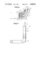
- FIG. 15 is a side elevation of a modification of the piezoelectric pressure sensor shown in FIG. 14;
- FIG. 16 is a plan view of the piezoelectric pressure sensor shown in FIG. 15;
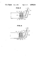
- FIG. 17 is front elevation of the piezoelectric pressure sensor shown in FIG. 15;
- FIGS. 18, 19 and 20 are similar view to FIGS. 15, 16 and 17, respectively, and show a further modification of the piezoelectric pressure sensor
- FIG. 21 is a fragmentary sectional view of another ninth embodiment of a piezoelectric pressure sensor
- FIG. 22 is side elevation of an annular insulator disk integral with an insulator collar
- FIG. 23 is a top plan view of the insulator shown in FIG. 22;
- FIG. 24 is a fragmentary sectional view of a further embodiment of a piezoelectric pressure sensor.
- FIG. 25 is a fragmentary sectional view of a still further embodiment of a piezoelectric pressure sensor.
- FIG. 1 there is shown a portion of an internal combustion engine 10 including an engine block 12 formed with a plurality of cylinders, only one being shown at 14, and a cylinder head 16.
- a piston 18 Slidably disposed in the cylinder 14 is a piston 18 to define a combustion chamber 20 between the cylinder 14 and the cylinder head 16.
- the cylinder head 16 is formed with a spark plug insert bore 22 formed with a female thread.
- the cylinder head 16 includes a first substantially flat wall 24 extending radially outward from an outer axial end of the spark plug insert bore 22.
- a spark plug 26 which includes a portion 28 formed with a male thread adapted to be threadedly engaged with the female thread of the spark plug insert bore 22.
- the spark plug 26 also includes a radially extending flange 30 formed with a second radially extending wall 32. This second radially extending wall 32 is opposed to and spaced from the first radially extending wall 24 when the spark plug 26 is screwed into the spark plug insert bore 22.
- a flat ring shaped piezoelectric pressure sensor 34 is disposed on the first radially extending wall 24. As best seen in FIG. 3, when the spark plug 26 is screwed into the spark plug insert bore 22, the piezoelectric pressure sensor 34 surrounds the male thread portion 28 of the spark plug 26 and disposed between the first and second radially extending walls 24, 32. In its operative position as shown in FIG.
- the sensor 34 is subject to a compression force because the spark plug 26 is screwed tightly into the spark plug insert bore 22. This compression force decreases as the combustion chamber pressure in the combustion chamber 20 increases. With the piezoelectric sensor 34, this compression force is converted into an electric signal which is taken out via an electric signal transmitter in the form of a lead 36. Thus, the combustion chamber pressure is measured in terms of an electric signal.
- the sensor 34 comprises an annular molded body 38 made of an insulator, an annular disk-like electrode 40 with an output terminal 42.
- the electrode 40 is interposed between a first piezoelectric element 44a and a second piezoelectric element 44b.
- a pair of annular pressure acting members 46 and 48 are disposed in such a manner as to interpose therebetween the first and second piezoelectric elements 44a and 44b.
- the pressure acting member 48 has an axially extending wall 50 disposed radially inward of the inner periphery of the other pressure acting member 46.
- an insulator collar 56 is fit around the axially extending wall 50.
- An annular gasket 52 is disposed radially outwardly of the axially extending wall 50 and is fitted on the pressure acting member 46.
- the axially extending wall 50 is curved radially outward to form a terminal end portion 54, thus holding the gasket 52 on the annular pressure acting member 46.
- the pressure acting member 48 is in abutting engagement with the first wall 24 of the cylinder head 16 with its terminal end portion 54 in abutting engagement with the second wall 32 of the spark plug 26.
- the pressure acting member 48 is subject to a torque upon tightening of the spark plug 26, thus reducing the transmission of torque to the gasket 52, pressure acting member 46, piezoelectric elements 44a, 44b, and electrode 40.
- the spark plug 26 can be tightened with a sufficiently great torque without any concern for damage of the sensor components.
- a great improvement has been made in installability of the piezoelectric pressure sensor 34.
- a terminal end portion 54 should be in locking engagement with a gasket 52 in order to prevent a relative rotation between a pressure acting member 48 and the gasket 52 during tightening operation of a spark plug 26.
- a plurality of portions on the periphery of the terminal end portion 54 firmly engage into the gasket 52, only one portion of which is shown at 58 in FIG. 4.
- a relatively long insulator collar 60 should be used to make it easy to secure insulation between the inner periphery of an electrode 40 and an axially extending wall 50 of a pressure acting member 48.
- This insulator collar 60 is as high as the top of a gasket 52 when the gasket 52 is disposed on a pressure acting member 46 lying on a piezoelectric element 44a before the axially extending wall 50 is curved radially outward to form a terminal end portion 54.
- the axially extending wall 50 is curved to form the terminal end portion 54 to lock the insulator collar 60 in the appropriate position for insulation of a space between the axially extending wall 50 and the inner periphery of the electrode 40.
- a gasket 52 with a protrusion 62 should be used.
- This protrusion 62 extends in the same direction as an output terminal 42 from electrode 40, so that it serves as an indicator upon tightening a spark plug 26.
- FIG. 7 shows, in reduced dimension, a piezoelectric pressure sensor 34C shown in FIG. 6.
- an annular insulator body 38 has a mast section 38a extending axially to enclose a connection where the output terminal 42 is connected to an output lead in the form of a shielded cable 36.
- FIG. 8 is a fragmentary sectional view of another embodiment of a piezoelectric pressure sensor 34D.
- This piezoelectric pressure sensor 34D is substantially the same as the piezoelectric pressure sensor 34A shown in FIG. 4 except that a pressure acting member 46' has a mast core portion 62 extending through a mast section 38a of an annular insulator body 38, and the mast core portion 62 has a sleeve 64 surrounding a portion where an output terminal 42 of an electrode 40 is connected to a core of a lead in the form of a shielded cable 36.
- This portion is surrounded by a protector tube 66 of an insulator and then fits into the sleeve 64.
- this portion where the output terminal 42 is connected to the core of the shielded cable 36 is securely held by the sleeve 64 via the protector tube 66 and thus it is securely protected.
- FIG. 9 is a fragmentary sectional view of still another embodiment of a piezoelectric pressure sensor 34E.
- This piezoelectric pressure sensor 34E is substantially the same as the piezoelectric pressure sensor 34D shown in FIG. 8 except that one 44a of the piezoelectric elements 44a, 44b has been replaced with an annular insulator member 68.
- This structure is advantageous in that the number of piezoelectric elements has been reduced to one. Besides, since the thickness of the annular insulator member 68 can be reduced, the total thickness of the annular section of the piezoelectric pressure sensor 34E can be made less than that of the piezoelectric pressure sensor shown in FIG. 8.
- FIGS. 10 and 11 still another embodiment of a piezoelectric pressure sensor 34F is described.
- a molded insulator body has been removed in FIGS. 10 and 11.
- the structure is substantially the same as that shown in FIG. 8 or 9 except that the gasket 52 has been replaced with a gasket 70 which has a radial extension 72 formed with a slot 74 receiving therein a mast core portion 62 at a portion adjacent a protector sleeve 64.
- This arrangement is effective in preventing relative rotation occurring between the gasket 70 and the protector sleeve 64.
- the mast portion 62 has at its end portion a second sleeve 76 holding a shieded wire 36.
- FIGS. 12 and 13 still another embodiment of a piezoelectric sensor 34G is described.
- This piezoelectric pressure sensor 34G is substantially the same as the piezoelectric pressure sensor 34F shown in FIGS. 10 and 11 except that instead of two separate sleeves 64 and 76, an elongate single sleeve 80 extends from an annular electrode, not shown, and serves as a mast portion. Another difference resides in that this elongate sleeve 80 is not covered with an insulator body.
- the piezoelectric pressure sensor 34G is positioned in a spark plug accommodation bore 82 which has a guide groove 84 axially extending along the wall of the bore 82.
- the elongate sleeve 80 is held in the axially extending groove 84 by a resilient plate 86 fixed to an upper portion of the sleeve 80. As best seen in FIG. 13, this plate 86 is resilient so that it keeps frictional contact with the guide groove 84 defining wall.
- the elongate sleeve 80 extends up to a level slightly above the open end of the spark plug accommodation bore 82. Extending from this sleeve 80 is a lead 36. The lead 36 further extends outward through a seal 88 positioned between the open end of the spark plug accommodation bore 82 and a plug boot 90.
- FIG. 14 shows a modification 34H which is different from the embodiment shown in FIG. 12 only in the provision of an external gasket 92 rather than the internal gasket 52 as shown in FIG. 9.
- a stop 94 is fixed to an elongate sleeve 80 at an upper end portion of a resilient plate 86 as viewed in FIG. 15.
- the configuration of the stop 94 may be readily understood from FIGS. 15, 16 and 17.
- the sleeve 80 is inserted deeply into a spark plug accommodation bore until the stop 94 abuts on the open end of the spark plug accommodation bore.
- a flange 96 extends from a stop 94 as shown in FIGS. 18, 19 and 20. Inserting work of a sleeve 80 till the abutting engagement of the stop 94 with the open end of a spark plug accommodation bore can be easily made by pressing down the flange 96.
- the insulator collar 56 and the annular insulator disk 68 are used. Since two separate insulator members 56 and 68, a difficulty is sometimes experienced in assembly.
- FIG. 21 shows a fragmentary sectional view of still another embodiment of a piezoelectric pressure sensor 34I wherein the above mentioned difficulty has been solved.
- the above-mentioned difficulty has been solved by using an annular insulator disk 100 having an integral insulator collar 102 as best seen in FIGS. 22 and 23.
- an axially extending wall 104 extends from an upper pressure acting member 46 rather than a lower pressure acting member 48.
- An axial end of the axially extending wall 104 is pressed into conformity with the inner periphery of the pressure acting member 48 with an axial end portion of the insulator collar 102 interposed therebetween.
- FIG. 24 shows still another embodiment of a piezoelectric pressure sensor 34J which is substantially the same as the just mentioned embodiment shown in FIG. 21 except that an annular insulator disk 100 with a relatively short insulator collar 102a is used and an electrode 40 is separated from a pressure acting member 46 by a piezoelectric element 44a and separated from the other pressure acting member 48 by the insulator disk 100.
- the insulator collar 102 or 102a is formed integral with the insulator disk 100, it is always positioned appropriately between the inner periphery of the annular disk-like electrode 40 and the adjacent axially extending wall 104, thus assuring insulation therebetween.
- FIG. 25 there is shown an embodiment of a piezoelectric pressure sensor 34K which is different from the embodiment 34E shown in FIG. 9 only in the use of an annular insulator disk 100 integral with a collar 102a instead of two separate insulators 56 and 68.
Abstract
Description
Claims (20)
Applications Claiming Priority (5)
| Application Number | Priority Date | Filing Date | Title |
|---|---|---|---|
| JP62-76050[U] | 1987-05-22 | ||
| JP1987076050U JPH0631395Y2 (en) | 1987-05-22 | 1987-05-22 | Washer pressure sensor |
| JP8104587U JPH0628671Y2 (en) | 1987-05-29 | 1987-05-29 | Washer pressure sensor |
| JP62-81045[U]JPX | 1987-05-29 | ||
| JP8552187U JPH0631398Y2 (en) | 1987-06-02 | 1987-06-02 | Positioning structure of washer pressure sensor |
Publications (1)
| Publication Number | Publication Date |
|---|---|
| US4898024A true US4898024A (en) | 1990-02-06 |
Family
ID=27302037
Family Applications (1)
| Application Number | Title | Priority Date | Filing Date |
|---|---|---|---|
| US07/192,944 Expired - Fee Related US4898024A (en) | 1987-05-22 | 1988-05-12 | Piezoelectric pressure measuring instrument |
Country Status (1)
| Country | Link |
|---|---|
| US (1) | US4898024A (en) |
Cited By (12)
| Publication number | Priority date | Publication date | Assignee | Title |
|---|---|---|---|---|
| EP0510515A1 (en) * | 1991-04-25 | 1992-10-28 | NGK Spark Plug Co. Ltd. | Device for temporarily holding pressure sensor in place within spark plug attaching hole of cylinder head |
| US5323643A (en) * | 1991-04-09 | 1994-06-28 | Ngk Spark Plug Co., Ltd. | Device for detecting change in internal pressure of cylinder |
| US5479817A (en) * | 1992-07-28 | 1996-01-02 | Ngk Spark Plug Co., Ltd. | Spark plug with built-in pressure sensor |
| US5712424A (en) * | 1996-03-25 | 1998-01-27 | The United States Of America As Represented By The Secretary Of The Navy | Method and apparatus for measuring diesel engine cylinder pressure |
| WO1999014571A1 (en) * | 1997-09-12 | 1999-03-25 | Southwest Research Institute | Load sensor for measuring engine cylinder pressure and seat occupant weight |
| EP1338880A1 (en) * | 2000-11-30 | 2003-08-27 | Ngk Spark Plug Co., Ltd. | Pressure sensor unit |
| US6732720B2 (en) | 2002-05-30 | 2004-05-11 | Monroe R. Kelemencky | Ultrasonic liquid fuel introduction system |
| EP1096140B1 (en) * | 1999-10-27 | 2004-12-15 | Denso Corporation | Attachment structure of glow plug |
| US20050229685A1 (en) * | 2004-03-31 | 2005-10-20 | Honda Motor Co., Ltd. | In-cylinder pressure detection device |
| US20060027013A1 (en) * | 2004-08-05 | 2006-02-09 | Honda Motor Co., Ltd. | Combustion pressure detecting apparatus |
| CN101435731A (en) * | 2004-08-05 | 2009-05-20 | 本田技研工业株式会社 | Combustion pressure detecting apparatus |
| US20100102801A1 (en) * | 2007-06-20 | 2010-04-29 | Ntn Corporation | Rotation sensor |
Citations (10)
| Publication number | Priority date | Publication date | Assignee | Title |
|---|---|---|---|---|
| US2773388A (en) * | 1952-08-18 | 1956-12-11 | Thomas W Prosser | Protective housing for instruments |
| US3505862A (en) * | 1967-05-11 | 1970-04-14 | Hans List | Piezoelectric pressure measuring instrument |
| JPS59108244A (en) * | 1982-12-10 | 1984-06-22 | Toshiba Corp | Manufacture of explosion-proof braun tube |
| US4566316A (en) * | 1983-01-10 | 1986-01-28 | Nissan Motor Co., Ltd. | Washer type pressure sensor |
| JPS61118635A (en) * | 1984-11-14 | 1986-06-05 | Nissan Motor Co Ltd | Washer type pressure sensor |
| US4602506A (en) * | 1984-06-29 | 1986-07-29 | Nissan Motor Co., Ltd. | Combustion pressure sensor arrangement |
| US4686861A (en) * | 1984-09-26 | 1987-08-18 | Ngk Spark Plug Co., Ltd. | Gasket type pressure sensor |
| JPH06114345A (en) * | 1992-10-26 | 1994-04-26 | Maki Seisakusho:Kk | Selecting device for vegetables and fruits |
| JPH06114344A (en) * | 1992-10-06 | 1994-04-26 | Ishikawajima Harima Heavy Ind Co Ltd | Glass bottle selecting system |
| JPH06114343A (en) * | 1992-10-06 | 1994-04-26 | Ishikawajima Harima Heavy Ind Co Ltd | Glass bottle selecting device |
-
1988
- 1988-05-12 US US07/192,944 patent/US4898024A/en not_active Expired - Fee Related
Patent Citations (10)
| Publication number | Priority date | Publication date | Assignee | Title |
|---|---|---|---|---|
| US2773388A (en) * | 1952-08-18 | 1956-12-11 | Thomas W Prosser | Protective housing for instruments |
| US3505862A (en) * | 1967-05-11 | 1970-04-14 | Hans List | Piezoelectric pressure measuring instrument |
| JPS59108244A (en) * | 1982-12-10 | 1984-06-22 | Toshiba Corp | Manufacture of explosion-proof braun tube |
| US4566316A (en) * | 1983-01-10 | 1986-01-28 | Nissan Motor Co., Ltd. | Washer type pressure sensor |
| US4602506A (en) * | 1984-06-29 | 1986-07-29 | Nissan Motor Co., Ltd. | Combustion pressure sensor arrangement |
| US4686861A (en) * | 1984-09-26 | 1987-08-18 | Ngk Spark Plug Co., Ltd. | Gasket type pressure sensor |
| JPS61118635A (en) * | 1984-11-14 | 1986-06-05 | Nissan Motor Co Ltd | Washer type pressure sensor |
| JPH06114344A (en) * | 1992-10-06 | 1994-04-26 | Ishikawajima Harima Heavy Ind Co Ltd | Glass bottle selecting system |
| JPH06114343A (en) * | 1992-10-06 | 1994-04-26 | Ishikawajima Harima Heavy Ind Co Ltd | Glass bottle selecting device |
| JPH06114345A (en) * | 1992-10-26 | 1994-04-26 | Maki Seisakusho:Kk | Selecting device for vegetables and fruits |
Cited By (19)
| Publication number | Priority date | Publication date | Assignee | Title |
|---|---|---|---|---|
| US5323643A (en) * | 1991-04-09 | 1994-06-28 | Ngk Spark Plug Co., Ltd. | Device for detecting change in internal pressure of cylinder |
| EP0510515A1 (en) * | 1991-04-25 | 1992-10-28 | NGK Spark Plug Co. Ltd. | Device for temporarily holding pressure sensor in place within spark plug attaching hole of cylinder head |
| US5313849A (en) * | 1991-04-25 | 1994-05-24 | Ngk Spark Plug Co., Ltd. | Device for temporarily holding pressure sensor in place within spark plug attaching hole of cylinder head |
| US5479817A (en) * | 1992-07-28 | 1996-01-02 | Ngk Spark Plug Co., Ltd. | Spark plug with built-in pressure sensor |
| US5712424A (en) * | 1996-03-25 | 1998-01-27 | The United States Of America As Represented By The Secretary Of The Navy | Method and apparatus for measuring diesel engine cylinder pressure |
| WO1999014571A1 (en) * | 1997-09-12 | 1999-03-25 | Southwest Research Institute | Load sensor for measuring engine cylinder pressure and seat occupant weight |
| US6134947A (en) * | 1997-09-12 | 2000-10-24 | Southwest Research Institute | Load sensor for measuring engine cylinder pressure and seat occupant weight |
| EP1096140B1 (en) * | 1999-10-27 | 2004-12-15 | Denso Corporation | Attachment structure of glow plug |
| US20040055388A1 (en) * | 2000-11-30 | 2004-03-25 | Koji Okazaki | Pressure sensor unit |
| EP1338880A1 (en) * | 2000-11-30 | 2003-08-27 | Ngk Spark Plug Co., Ltd. | Pressure sensor unit |
| EP1338880A4 (en) * | 2000-11-30 | 2005-07-27 | Ngk Spark Plug Co | Pressure sensor unit |
| US7107819B2 (en) * | 2000-11-30 | 2006-09-19 | Ngk Spark Plug Co., Ltd. | Pressure sensor unit having a ring-like pressure sensing element |
| US6732720B2 (en) | 2002-05-30 | 2004-05-11 | Monroe R. Kelemencky | Ultrasonic liquid fuel introduction system |
| US20050229685A1 (en) * | 2004-03-31 | 2005-10-20 | Honda Motor Co., Ltd. | In-cylinder pressure detection device |
| US7171846B2 (en) * | 2004-03-31 | 2007-02-06 | Ngk Sparkplug Co. Ltd. | In-cylinder pressure detection device |
| US20060027013A1 (en) * | 2004-08-05 | 2006-02-09 | Honda Motor Co., Ltd. | Combustion pressure detecting apparatus |
| CN101435731A (en) * | 2004-08-05 | 2009-05-20 | 本田技研工业株式会社 | Combustion pressure detecting apparatus |
| CN101435731B (en) * | 2004-08-05 | 2012-10-10 | 本田技研工业株式会社 | Combustion pressure detecting apparatus |
| US20100102801A1 (en) * | 2007-06-20 | 2010-04-29 | Ntn Corporation | Rotation sensor |
Similar Documents
| Publication | Publication Date | Title |
|---|---|---|
| US4898024A (en) | Piezoelectric pressure measuring instrument | |
| US4969352A (en) | Combustion pressure sensor | |
| US4296887A (en) | Heat protected fuel injection plug for internal combustion engines | |
| US5716223A (en) | Spark plug boot insulator | |
| US4392082A (en) | Pressure-sensitive ignition plug | |
| US6570304B1 (en) | Spark plug cap and spark plug fitting method | |
| US4145106A (en) | Shielding device for oriented spark plugs | |
| US4394598A (en) | Spark plug for internal combustion engines | |
| US6094990A (en) | Spark plug with concentric pressure sensor | |
| US4947809A (en) | Ignition boot | |
| EP0554045B1 (en) | Spark plug | |
| US6559577B2 (en) | Pressure sensor-incorporating spark plug | |
| EP0509205B1 (en) | Tool for loosening or tightening spark plug | |
| JP2004505406A (en) | Spark plug and associated spark plug connector for receiving a pressure sensor | |
| US4275334A (en) | Integral spark plug coil for aircraft-type plug | |
| US6302712B1 (en) | Spark plug wire boot securing system | |
| EP0694773B1 (en) | Device for detecting change in internal pressure of cylinder | |
| US4150865A (en) | Magneto to spark plug aircraft wiring harness | |
| CA2013127C (en) | Combustion pressure sensor | |
| US6475002B2 (en) | Spark plug wire boot securing system | |
| JPH045896Y2 (en) | ||
| JPS60201231A (en) | Pressure detector of internal-combustion engine | |
| JPH0122359Y2 (en) | ||
| JPH0544152B2 (en) | ||
| JPS6182137A (en) | Bolt incorporating detector for combustion pressure in engine |
Legal Events
| Date | Code | Title | Description |
|---|---|---|---|
| AS | Assignment |
Owner name: NISSAN MOTOR CO., LTD., NO. 2, TAKARA-CHO, KANAGAW Free format text: ASSIGNMENT OF ASSIGNORS INTEREST.;ASSIGNOR:TAKEUCHI, KIYOSHI;REEL/FRAME:004889/0493 Effective date: 19880411 Owner name: NISSAN MOTOR CO., LTD., JAPAN Free format text: ASSIGNMENT OF ASSIGNORS INTEREST;ASSIGNOR:TAKEUCHI, KIYOSHI;REEL/FRAME:004889/0493 Effective date: 19880411 |
|
| FEPP | Fee payment procedure |
Free format text: PAYOR NUMBER ASSIGNED (ORIGINAL EVENT CODE: ASPN); ENTITY STATUS OF PATENT OWNER: LARGE ENTITY |
|
| FPAY | Fee payment |
Year of fee payment: 4 |
|
| FPAY | Fee payment |
Year of fee payment: 8 |
|
| REMI | Maintenance fee reminder mailed | ||
| LAPS | Lapse for failure to pay maintenance fees | ||
| STCH | Information on status: patent discontinuation |
Free format text: PATENT EXPIRED DUE TO NONPAYMENT OF MAINTENANCE FEES UNDER 37 CFR 1.362 |
|
| FP | Lapsed due to failure to pay maintenance fee |
Effective date: 20020206 |