US4899892A - Earthquake-resistant electronic equipment frame - Google Patents
Earthquake-resistant electronic equipment frame Download PDFInfo
- Publication number
- US4899892A US4899892A US07/165,318 US16531888A US4899892A US 4899892 A US4899892 A US 4899892A US 16531888 A US16531888 A US 16531888A US 4899892 A US4899892 A US 4899892A
- Authority
- US
- United States
- Prior art keywords
- electronic equipment
- central portion
- side member
- equipment frame
- base
- Prior art date
- Legal status (The legal status is an assumption and is not a legal conclusion. Google has not performed a legal analysis and makes no representation as to the accuracy of the status listed.)
- Expired - Fee Related
Links
Images
Classifications
-
- H—ELECTRICITY
- H05—ELECTRIC TECHNIQUES NOT OTHERWISE PROVIDED FOR
- H05K—PRINTED CIRCUITS; CASINGS OR CONSTRUCTIONAL DETAILS OF ELECTRIC APPARATUS; MANUFACTURE OF ASSEMBLAGES OF ELECTRICAL COMPONENTS
- H05K5/00—Casings, cabinets or drawers for electric apparatus
- H05K5/02—Details
- H05K5/0204—Mounting supporting structures on the outside of casings
-
- H—ELECTRICITY
- H02—GENERATION; CONVERSION OR DISTRIBUTION OF ELECTRIC POWER
- H02B—BOARDS, SUBSTATIONS OR SWITCHING ARRANGEMENTS FOR THE SUPPLY OR DISTRIBUTION OF ELECTRIC POWER
- H02B1/00—Frameworks, boards, panels, desks, casings; Details of substations or switching arrangements
- H02B1/54—Anti-seismic devices or installations
-
- H—ELECTRICITY
- H02—GENERATION; CONVERSION OR DISTRIBUTION OF ELECTRIC POWER
- H02B—BOARDS, SUBSTATIONS OR SWITCHING ARRANGEMENTS FOR THE SUPPLY OR DISTRIBUTION OF ELECTRIC POWER
- H02B1/00—Frameworks, boards, panels, desks, casings; Details of substations or switching arrangements
- H02B1/26—Casings; Parts thereof or accessories therefor
- H02B1/30—Cabinet-type casings; Parts thereof or accessories therefor
Definitions
- This invention relates to electronic equipment frames, and is particularly concerned with earthquake-resistant frames for communications equipment.
- Free-standing electronic equipment frames typically have low natural resonance frequencies in the range from 1 to 10 Hz. In earthquakes, the highest energy dissipation occurs in the 4 to 5 Hz region, thereby making the frames vulnerable to earthquake induced damage. Increasing the natural frequency of the frames above this range decreases their sensitivity.
- the base of a tall, slender, frame moves with the floor to which it is anchored. If the frame is sufficiently rigid and well anchored it will closely follow the motions of the base and floor. If, however, the frame is more flexible, it will move at a rate different to that of the base and floor, and consequently it may experience high stresses and deflections.
- the frequency of floor motion on an upper floor of a building may be much higher than that at ground level. If the natural frequency of the frame is sufficiently low, the frequency of floor motion may match that of the frame, causing resonance. In this state, the frame will amplify any motion received from the floor and undergo even larger deflections. It may then topple or collapse, resulting in serious damage to components within.
- an object of this invention is to provide an electronic equipment frame which facilitates protection of equipment mounted therein from damage due to earthquakes and seismic motion.
- an electronic equipment frame comprising: a base; two elongate side members, secured to and extending upwardly from the base, for supporting electronic equipment therebetween; and a top member secured to and extending between upper ends of the side members; each side member having a front flange, a rear flange, and a central portion extending therebetween, the central portion including an inverted-V portion extending from a general plane of the central portion on the same side thereof as the front and rear flanges, along substantially the entire length of the side member.
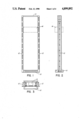
- FIGS. 1, 2, and 3 illustrate front, side, and plan views respectively of a communications equipment frame in accordance with an embodiment of the invention
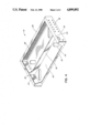
- FIG. 4 illustrates a base of the frame of FIGS. 1 to 3;
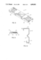
- FIGS. 5 and 6 illustrate a top member of the frame of FIGS. 1 to 3;
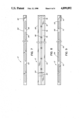
- FIGS. 7 to 10 illustrate a side member of the frame of FIGS. 1 to 3.
- the communications equipment frame illustrated therein comprises a base 10, two side members 12, and a top member 14, and is intended for supporting in known manner modular shelves of communications equipment, such as a shelf 16 represented by broken lines in FIGS. 1 and 2.
- the top member 14 is welded to the side members 12, which are bolted to the base 10.
- the base 10 is anchored by bolts to a concrete floor in which the communications equipment carried in use by the frame is ultimately installed.
- the base 10 is shown in greater detail in FIG. 4, and comprises a floor 20, vertical sides 22 terminating in upper horizontal flanges 24, a vertical back 26 also terminating in an upper horizontal flange 28, a recessed front 30, and a vertical transverse member 32 extending between the sides 22.
- the joints between the various parts of the base 10 are seam welded for strength and rigidity.
- the floor 20 includes four angled slots 34 via which the anchor bolts referred to above extend for securing the base 10 to a concrete floor.
- the sides 22 include an array of holes 36 via four of which each side member 12 is bolted to a respective side 22.
- the back 26 includes vertical louvres to facilitate ventilation.
- FIGS. 5 and 6 illustrate the top member 14 in greater detail, FIG. 5 showing an isometric view and FIG. 6 showing an end elevation.
- the top member 14 comprises a member 40 with front and back flanges 42 depending therefrom, and a stiffening bar 44 also depending therefrom and extending transversely parallel to the flanges 42 and positioned therebetween. Rectangular apertures 46 in the member 40 allow for the anchoring of cable ducts that carry the cables from and to the communications equipment.
- the member 40 also includes holes 48, with nuts 50 aligned therewith and welded to the underside of the member 40, to permit bolts to be screwed therein to fit any framework extension that would be needed by customers due to changes in ceiling heights of their central offices.
- FIGS. 7 to 10 illustrate the left (as viewed in FIG. 1) side member 12 in greater detail; the right side member 12 has a similar but mirrored form.
- the top end of the side member 12 is shown at the left of the drawing, and the bottom end at the right.
- FIGS. 7 to 9 show the side member 12 as seen from respectively the front, left, and rear of the frame as illustrated in FIG. 1.
- the side member 12 comprises an elongate member 60, to which are welded a bottom plate 62 and an upper bossed plate 64 as described further below.
- FIG. 10 illustrates a general cross-section of the elongate member 60.
- the elongate member 60 has a general cross-section comprising a relatively wide front flange 66 terminating in a perpendicular rearwardly-directed lip 68, a relatively narrow rear flange 70 terminating in a perpendicular forwardly-directed lip 72, and a central portion 74 extending perpendicularly to the flanges 66 and 70 between the unlipped edges thereof, the central portion 74 having centrally therein an upstanding inverted-V portion 76 extending from the general plane of the central portion 74 on the same side as the flanges 66 and 70.
- the inverted-V portion 76 thus lies between the flanges 66 and 70, and in this embodiment of the invention has an apical angle of 90 degrees.
- the bottom plate 62 is welded to the central portion 74 of the member 60 at its bottom end, and as shown in FIG. 8 four holes 78 extend through the member 60 and plate 62 via which the side member 12 is bolted to the base 10 as discussed above.
- the plate 64 is welded to the central portion 74 of the member 60 towards its top end, the inverted-V portion 76 being removed at this point, and carries a threaded boss 80 into which a lifting hook may be screwed, to provide on each side of the frame a lifting point for the frame and equipment carried therein.
- the relatively wide front flange 66 has, regularly spaced along substantially its entire length adjacent the central portion 74, holes 82 for use in mounting shelves such as the shelf 16 in FIGS. 1 and 2. As shown in FIGS. 7 and 9, this flange 66 also has, adjacent the lip 68, elongate slots 84 through which cables from the front of such shelves can be routed to run within a cable duct defined between the flanges 66 and 70.
- the inverted-V portion 76 has spaced periodically along its length apertures or knock-outs 86 which enable cable ties to pass therethrough.
- the relatively narrow rear flange 70 also has holes 88 spaced along substantially its entire length, to which plates may be attached for securing together adjacent equipment frames positioned side-by-side.
- a frame as described above, using one-eighth inch thick steel for the side members 12 and three-sixteenths inch thick steel for the base 10 and top member 14, has relatively high natural frequencies and can be provided at relatively low cost.
- Such a frame has been found, from earthquake simulation testing on a horizontal shaking table, to meet standards prescribed for upper floor locations in buildings, in accordance with Bell Communications Research Specifications in their document TR-EOP-000063, Network Equipment-Building System (NEBS) General Equipment Requirements.
- NEBS Network Equipment-Building System
Abstract
Description
Claims (7)
Priority Applications (1)
| Application Number | Priority Date | Filing Date | Title |
|---|---|---|---|
| US07/165,318 US4899892A (en) | 1988-03-08 | 1988-03-08 | Earthquake-resistant electronic equipment frame |
Applications Claiming Priority (1)
| Application Number | Priority Date | Filing Date | Title |
|---|---|---|---|
| US07/165,318 US4899892A (en) | 1988-03-08 | 1988-03-08 | Earthquake-resistant electronic equipment frame |
Publications (1)
| Publication Number | Publication Date |
|---|---|
| US4899892A true US4899892A (en) | 1990-02-13 |
Family
ID=22598409
Family Applications (1)
| Application Number | Title | Priority Date | Filing Date |
|---|---|---|---|
| US07/165,318 Expired - Fee Related US4899892A (en) | 1988-03-08 | 1988-03-08 | Earthquake-resistant electronic equipment frame |
Country Status (1)
| Country | Link |
|---|---|
| US (1) | US4899892A (en) |
Cited By (20)
| Publication number | Priority date | Publication date | Assignee | Title |
|---|---|---|---|---|
| US4988008A (en) * | 1989-06-19 | 1991-01-29 | Siemens Aktiengesellschaft | Supporting framework for a control cabinet |
| US5284254A (en) * | 1992-06-24 | 1994-02-08 | B-Line Systems, Inc. | Rack for electrical equipment |
| WO1998056224A1 (en) * | 1997-06-06 | 1998-12-10 | Abb Combustion Engineering Nuclear Power, Inc. | Programmable logic controller seismic support bracket for nuclear applications |
| US5983590A (en) * | 1997-05-29 | 1999-11-16 | The Crown Division | Earthquake resistant equipment rack |
| US6006925A (en) * | 1997-06-03 | 1999-12-28 | Hendry Mechanical Works | Equipment rack system |
| US6202860B1 (en) | 1999-10-07 | 2001-03-20 | W. H. Stewart Co. | Electronic equipment enclosure |
| US6293637B1 (en) | 2000-05-12 | 2001-09-25 | Amco Engineering Co. | Earthquake-resistant electronic equipment frame |
| WO2002045225A2 (en) * | 2000-11-30 | 2002-06-06 | L & P Property Management Company | Earthquake resistant equipment rack |
| US6481582B1 (en) | 2001-06-04 | 2002-11-19 | Cooper Technologies Company | Rack |
| US6517174B2 (en) | 1998-06-23 | 2003-02-11 | Hendry Telephone Products | Equipment mounting racks and cabinets |
| US6561602B1 (en) | 1998-06-23 | 2003-05-13 | Hendry Mechanical Works | Equipment mounting racks and cabinets |
| US6605777B1 (en) * | 2002-07-29 | 2003-08-12 | Amco Engineering Co. | Earthquake-resistant electronic equipment frame |
| US20040069725A1 (en) * | 2002-07-10 | 2004-04-15 | Adducci Samuel J. | Seismically resistant network equipment rack |
| US20040183409A1 (en) * | 2001-01-23 | 2004-09-23 | Cooper Technologies Company | Electrical equipment enclosure |
| US6889853B2 (en) | 2001-12-20 | 2005-05-10 | Sanmina Enclosure Systems Division | Earthquake-resistant equipment rack |
| US20060043031A1 (en) * | 2004-08-26 | 2006-03-02 | Cooper Technologies Company | Electronic equipment rack |
| US20090283488A1 (en) * | 2008-05-19 | 2009-11-19 | Chatsworth Products, Inc. | Seismically hardened two-post electronic equipment rack |
| US20210037669A1 (en) * | 2018-02-13 | 2021-02-04 | Framatome | Subrack assembly, associated rack and assembly method |
| US20220381051A1 (en) * | 2021-05-25 | 2022-12-01 | Vertiv Corporation | Outdoor seismic equipment enclosures |
| US11686911B2 (en) | 2020-09-17 | 2023-06-27 | Panduit Corp. | Optical distribution and splice frame including enclosures |
Citations (9)
| Publication number | Priority date | Publication date | Assignee | Title |
|---|---|---|---|---|
| US3487948A (en) * | 1967-03-15 | 1970-01-06 | Ebauches Sa | Holder for flanged containers |
| US4074811A (en) * | 1975-10-15 | 1978-02-21 | Filak Andrew M | Multi-level knock-down framework structure for supporting a plurality of objects |
| US4153164A (en) * | 1978-06-13 | 1979-05-08 | Kasper Instruments, Inc. | Carrier for semiconductive wafers |
| GB2074386A (en) * | 1980-04-21 | 1981-10-28 | Vero Electronics Ltd | Electrical equipment assembly |
| US4447856A (en) * | 1980-10-24 | 1984-05-08 | Fujitsu Limited | Shelf unit for electronic communication devices |
| US4464074A (en) * | 1981-12-28 | 1984-08-07 | United States Gypsum Company | Connector and web stiffener |
| US4496057A (en) * | 1982-07-26 | 1985-01-29 | Fujitsu Limited | Rack structure for mounting a communication apparatus |
| US4497411A (en) * | 1982-04-19 | 1985-02-05 | Northern Telecom Limited | Distributing frame for telecommunications systems |
| US4531640A (en) * | 1983-09-12 | 1985-07-30 | Electronic Solutions | Frame for supporting circuit boards |
-
1988
- 1988-03-08 US US07/165,318 patent/US4899892A/en not_active Expired - Fee Related
Patent Citations (9)
| Publication number | Priority date | Publication date | Assignee | Title |
|---|---|---|---|---|
| US3487948A (en) * | 1967-03-15 | 1970-01-06 | Ebauches Sa | Holder for flanged containers |
| US4074811A (en) * | 1975-10-15 | 1978-02-21 | Filak Andrew M | Multi-level knock-down framework structure for supporting a plurality of objects |
| US4153164A (en) * | 1978-06-13 | 1979-05-08 | Kasper Instruments, Inc. | Carrier for semiconductive wafers |
| GB2074386A (en) * | 1980-04-21 | 1981-10-28 | Vero Electronics Ltd | Electrical equipment assembly |
| US4447856A (en) * | 1980-10-24 | 1984-05-08 | Fujitsu Limited | Shelf unit for electronic communication devices |
| US4464074A (en) * | 1981-12-28 | 1984-08-07 | United States Gypsum Company | Connector and web stiffener |
| US4497411A (en) * | 1982-04-19 | 1985-02-05 | Northern Telecom Limited | Distributing frame for telecommunications systems |
| US4496057A (en) * | 1982-07-26 | 1985-01-29 | Fujitsu Limited | Rack structure for mounting a communication apparatus |
| US4531640A (en) * | 1983-09-12 | 1985-07-30 | Electronic Solutions | Frame for supporting circuit boards |
Cited By (29)
| Publication number | Priority date | Publication date | Assignee | Title |
|---|---|---|---|---|
| US4988008A (en) * | 1989-06-19 | 1991-01-29 | Siemens Aktiengesellschaft | Supporting framework for a control cabinet |
| US5284254A (en) * | 1992-06-24 | 1994-02-08 | B-Line Systems, Inc. | Rack for electrical equipment |
| US5983590A (en) * | 1997-05-29 | 1999-11-16 | The Crown Division | Earthquake resistant equipment rack |
| US6006925A (en) * | 1997-06-03 | 1999-12-28 | Hendry Mechanical Works | Equipment rack system |
| WO1998056224A1 (en) * | 1997-06-06 | 1998-12-10 | Abb Combustion Engineering Nuclear Power, Inc. | Programmable logic controller seismic support bracket for nuclear applications |
| US6128202A (en) * | 1997-06-06 | 2000-10-03 | Ce Nuclear Power Llc | Programmable logic controller seismic support bracket for nuclear applications |
| US6527351B1 (en) | 1998-06-23 | 2003-03-04 | Hendry Mechanical Works | Equipment mounting racks and cabinets |
| US6517174B2 (en) | 1998-06-23 | 2003-02-11 | Hendry Telephone Products | Equipment mounting racks and cabinets |
| US6561602B1 (en) | 1998-06-23 | 2003-05-13 | Hendry Mechanical Works | Equipment mounting racks and cabinets |
| US6202860B1 (en) | 1999-10-07 | 2001-03-20 | W. H. Stewart Co. | Electronic equipment enclosure |
| US6293637B1 (en) | 2000-05-12 | 2001-09-25 | Amco Engineering Co. | Earthquake-resistant electronic equipment frame |
| WO2002045225A2 (en) * | 2000-11-30 | 2002-06-06 | L & P Property Management Company | Earthquake resistant equipment rack |
| WO2002045225A3 (en) * | 2000-11-30 | 2003-01-09 | Crown North America | Earthquake resistant equipment rack |
| US6951288B2 (en) * | 2000-11-30 | 2005-10-04 | L&P Property Management Company | Earthquake resistant equipment rack |
| US20040020873A1 (en) * | 2000-11-30 | 2004-02-05 | Henderson Kevin R. | Earthquake resistant equipment rack |
| US20040183409A1 (en) * | 2001-01-23 | 2004-09-23 | Cooper Technologies Company | Electrical equipment enclosure |
| US6481582B1 (en) | 2001-06-04 | 2002-11-19 | Cooper Technologies Company | Rack |
| US6889853B2 (en) | 2001-12-20 | 2005-05-10 | Sanmina Enclosure Systems Division | Earthquake-resistant equipment rack |
| US20040069725A1 (en) * | 2002-07-10 | 2004-04-15 | Adducci Samuel J. | Seismically resistant network equipment rack |
| US6605777B1 (en) * | 2002-07-29 | 2003-08-12 | Amco Engineering Co. | Earthquake-resistant electronic equipment frame |
| US20060043031A1 (en) * | 2004-08-26 | 2006-03-02 | Cooper Technologies Company | Electronic equipment rack |
| US20090283488A1 (en) * | 2008-05-19 | 2009-11-19 | Chatsworth Products, Inc. | Seismically hardened two-post electronic equipment rack |
| US8424691B2 (en) | 2008-05-19 | 2013-04-23 | Chatsworth Products, Inc. | Seismically hardened two-post electronic equipment rack |
| US20210037669A1 (en) * | 2018-02-13 | 2021-02-04 | Framatome | Subrack assembly, associated rack and assembly method |
| US11792951B2 (en) * | 2018-02-13 | 2023-10-17 | Framatome | Subrack assembly, associated rack and assembly method |
| US11686911B2 (en) | 2020-09-17 | 2023-06-27 | Panduit Corp. | Optical distribution and splice frame including enclosures |
| US11921339B2 (en) | 2020-09-17 | 2024-03-05 | Panduit Corp. | Optical distribution and splice frame including vertical cable managers |
| US11947178B2 (en) | 2020-09-17 | 2024-04-02 | Panduit Corp. | Optical distribution and splice frame including cassettes |
| US20220381051A1 (en) * | 2021-05-25 | 2022-12-01 | Vertiv Corporation | Outdoor seismic equipment enclosures |
Similar Documents
| Publication | Publication Date | Title |
|---|---|---|
| US4899892A (en) | Earthquake-resistant electronic equipment frame | |
| CA1255733A (en) | Beam-type work station system | |
| US5383723A (en) | Earthquake resistant electronic equipment frame | |
| US7874433B2 (en) | Seismically sound rack system | |
| US5969292A (en) | Overhead cabling system for telecommunication switching center | |
| US5946867A (en) | Modular earthquake support for raised floor | |
| US6036290A (en) | Seismic subframe for electrical enclosure | |
| US6425648B1 (en) | Modular and flexible server frame enclosure | |
| US6349837B1 (en) | Stiffened relay rack | |
| US6425488B1 (en) | Integrated flexible frame tie down retention system for raised and non-raised floor applications | |
| US6365830B1 (en) | Overhead cabling system for a telecommunications switching center | |
| US20060043031A1 (en) | Electronic equipment rack | |
| JPH11251770A (en) | Rack for communication apparatus | |
| EP0367176A3 (en) | Interior panel unit for permitting arrangement of cables and devices on room floor | |
| US10517187B1 (en) | Modular rack assembly | |
| US7143552B2 (en) | Supporting spine structure for modular office furniture | |
| US11459753B2 (en) | Modular ceiling system | |
| US6301837B1 (en) | Rack assembly for supporting electronic units | |
| CA1290441C (en) | Earthquake-resistant electronic equipment frame | |
| JP6315227B2 (en) | Grain shelf type ceiling structure and construction method of grape shelf type ceiling structure | |
| US8290331B2 (en) | Spacer box and interbay cable management panel | |
| US6889853B2 (en) | Earthquake-resistant equipment rack | |
| US11821205B2 (en) | Modular ceiling system | |
| CN211369613U (en) | Edge protection device is faced to assembly type structure | |
| CN206888452U (en) | A kind of floor support bracket |
Legal Events
| Date | Code | Title | Description |
|---|---|---|---|
| AS | Assignment |
Owner name: NORTHERN TELECOM LIMITED, CANADA Free format text: ASSIGNMENT OF ASSIGNORS INTEREST.;ASSIGNOR:RHEAULT, DENIS J. A.;REEL/FRAME:005005/0163 Effective date: 19880404 |
|
| FEPP | Fee payment procedure |
Free format text: PAYOR NUMBER ASSIGNED (ORIGINAL EVENT CODE: ASPN); ENTITY STATUS OF PATENT OWNER: LARGE ENTITY |
|
| FPAY | Fee payment |
Year of fee payment: 4 |
|
| FPAY | Fee payment |
Year of fee payment: 8 |
|
| AS | Assignment |
Owner name: NORTEL NETWORKS CORPORATION, CANADA Free format text: CHANGE OF NAME;ASSIGNOR:NORTHERN TELECOM LIMITED;REEL/FRAME:010567/0001 Effective date: 19990429 |
|
| AS | Assignment |
Owner name: NORTEL NETWORKS LIMITED, CANADA Free format text: CHANGE OF NAME;ASSIGNOR:NORTEL NETWORKS CORPORATION;REEL/FRAME:011195/0706 Effective date: 20000830 Owner name: NORTEL NETWORKS LIMITED,CANADA Free format text: CHANGE OF NAME;ASSIGNOR:NORTEL NETWORKS CORPORATION;REEL/FRAME:011195/0706 Effective date: 20000830 |
|
| REMI | Maintenance fee reminder mailed | ||
| LAPS | Lapse for failure to pay maintenance fees | ||
| STCH | Information on status: patent discontinuation |
Free format text: PATENT EXPIRED DUE TO NONPAYMENT OF MAINTENANCE FEES UNDER 37 CFR 1.362 |
|
| FP | Lapsed due to failure to pay maintenance fee |
Effective date: 20020213 |