US4899926A - Two way mailer - Google Patents
Two way mailer Download PDFInfo
- Publication number
- US4899926A US4899926A US07/333,014 US33301489A US4899926A US 4899926 A US4899926 A US 4899926A US 33301489 A US33301489 A US 33301489A US 4899926 A US4899926 A US 4899926A
- Authority
- US
- United States
- Prior art keywords
- return
- panel
- envelope
- perforated
- lines
- Prior art date
- Legal status (The legal status is an assumption and is not a legal conclusion. Google has not performed a legal analysis and makes no representation as to the accuracy of the status listed.)
- Expired - Lifetime
Links
Images


Classifications
-
- B—PERFORMING OPERATIONS; TRANSPORTING
- B65—CONVEYING; PACKING; STORING; HANDLING THIN OR FILAMENTARY MATERIAL
- B65D—CONTAINERS FOR STORAGE OR TRANSPORT OF ARTICLES OR MATERIALS, e.g. BAGS, BARRELS, BOTTLES, BOXES, CANS, CARTONS, CRATES, DRUMS, JARS, TANKS, HOPPERS, FORWARDING CONTAINERS; ACCESSORIES, CLOSURES, OR FITTINGS THEREFOR; PACKAGING ELEMENTS; PACKAGES
- B65D27/00—Envelopes or like essentially-rectangular containers for postal or other purposes having no structural provision for thickness of contents
- B65D27/06—Envelopes or like essentially-rectangular containers for postal or other purposes having no structural provision for thickness of contents with provisions for repeated re-use
Definitions
- This invention relates generally to envelopes, and is concerned in particular with a two way mailer comprising the separable combination of a forwarding envelope and a return envelope formed from a single blank of sheet material.
- the present invention is directed to a novel and improved two way mailer which either obviates or at the very least substantially minimizes the above-noted drawbacks.
- the two way mailer of the present invention includes a return envelope having a rear panel which also serves as the rear panel for the forwarding envelope.
- the return envelope is detachably secured to the forwarding envelope along perforated lines which are located exclusively or substantially exclusively in the common rear panel, thereby leaving the front panel of the forwarding envelope essentially free of unsightly perforations.
- Critical end segments of the aforesaid perforated lines are overlapped by the front closure flap of the forwarding envelope, thereby safeguarding the mailer from inadvertent violation by automatic processing equipment.
- the front closure flap of the forwarding envelope is opened in a conventional manner, and the return envelope is readily separable from the front panel of the forwarding envelope, thus facilitating both access to the contents of the forwarding envelope, and subsequent use of the return envelope. Because the perforated lines are located exclusively or substantially exclusively in the rear panel, separation of the return envelope is effected without damage to any contents of the forwarding envelope.
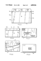
- FIG. 1 is a plan view of a blank used to form one embodiment of the invention
- FIGS. 2-5 are views showing the sequential steps followed to form a two way mailer from the blank shown in FIG. 1;
- FIGS. 6 and 7 are rear and front views respectively of the resulting two way mailer after the front closure flap has been folded and sealed;
- FIG. 8 is a rear view of the two way mailer, showing the front closure flap opened, and the return envelope in the process of being separated;
- FIG. 9 is a front view of the return envelope following its separation from the forwarding envelope
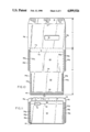
- FIG. 10 is a plan view of a blank used to form a second embodiment of the invention.
- FIGS. 11 and 12 are views showing the sequential steps used to form a two way mailer from the second embodiment blank shown in FIG. 10;
- FIGS. 13 and 14 are rear and front views respectively of the second embodiment two way mailer after the front closure flap has been folded and sealed.
- FIG. 15 is a front view of the return envelope after it has been separated and prior to its being closed and sealed.
- a first embodiment of a two way mailer in accordance with the present invention comprising a single blank of sheet material having first and second sections A,B separately interconnected at a first perforated line 10.
- the first section A includes a front panel 12 having a bottom edge coincident with the first perforated line 10, a top edge 14, and side edges 16a, 16b.
- a front closure flap 18 extends outwardly from the top edge 14 of the first panel.
- the second section B includes a rear panel 20 and a return panel 22 joined one to the other at a fold line 24.
- the rear panel has a top edge 25, a bottom edge coincident with the fold line 24, and side edges 26a, 26b.
- the return panel 22 likewise has a bottom edge coincident with the fold line 24, a top edge 28, and side edges 30a, 30b.
- Second perforated lines 32a, 32b are located in the rear panel 20 at locations spaced inwardly from and parallel to the respective side edges 26a, 26b.
- the second perforated lines 32a, 32b are perpendicular to and intersect with the first perforated line 10.
- the second perforated lines 32a, 32b are located substantially exclusively in the rear panel, i.e., in the second section B.
- the fold line 24 and the top edges 25, 28 are parallel to the first perforated line 10.
- a first adhesive means comprises glue lines 34a, 34b located on the rear panel 20 at locations spaced respectively inwardly of the second perforated lines 32a, 32b.
- a second adhesive means comprises glue lines 36a, 36b located on the rear panel at locations spaced respectively outwardly of the second perforated lines 32a, 32b.
- the front panel 12 may be provided with a window opening 38 for viewing a mailing address printed on the contents to be stuffed into the forwarding envelope. Additional window openings (not shown) also may be provided at selected locations in the front panel.
- the front panel 12 may also be provided with side flaps which are foldable inwardly about fold lines 42a, 42b aligned with the side edges 26a, 26b of the rear panel 20.
- a third adhesive means comprising glue spots 44 is provided on the front closure flap 18.
- a return closure flap 46 extends outwardly from the top edge 25 of the rear panel.
- the return closure flap is detachably joined to the front panel 12 at the first perforated line 10, and is provided with a fourth adhesive means in the form of a glue line 48.
- the return panel 22 is also provided with side flaps 50a, 50b which are foldable inwardly about fold lines 52a, 52b aligned respectively with the second perforated lines 32a, 32b.
- the blank illustrated in FIG. 1 is formed into a two way mailer in the following manner: as illustrated in FIG. 2, the side flaps 50a, 50b are initially folded inwardly about their respective fold lines 52a, 52b onto the return panel 22. Next, as shown in FIG. 3, the return panel 22 is folded about fold line 24 onto the rear panel 20, and the previously inwardly folded side flaps 50a, 50b are adhered to the rear panel by means of the glue lines 34a, 34b, thereby forming a return envelope.
- the side flaps 40a, 40b are folded inwardly about their respective fold lines 42a, 42b , onto the front panel 12.
- the return envelope is folded about the first perforated line 10 onto the front panel 12, and the inwardly folded side flaps 40a, 40b are adhered to the rear panel 20 by means of the glue lines 36a, 36b to thereby form the forwarding envelope.
- the front closure flap 18 is folded about the top edge 14 of the front panel 12 and is adhered to the rear panel 20 by means of the glue spots 44.
- the front of the thus filled and closed forwarding envelope is illustrated in FIG. 7.
- the recipient's address may be printed on the contents of the forwarding envelope for viewing through the window 38, and the sender's return address as well as any other appropriate indices, including advertising messages, may be printed on the front panel 12.
- folding sequence may be varied to accommodate various designs and production techniques. For example, under certain circumstances, it might be desirable to fold in both sets of side flaps 50a, 50b, 40a, 40b before folding the return and rear panels 22, 20.
- FIGS. 6 and 7 show that the front panel 12 is free of unsightly perforated lines. More particularly, the first perforated line 10 runs along the bottom edge of the envelope, and the second perforated lines 32a, 32b are located exclusively or substantially exclusively in the rear panel 20. Most importantly, the second perforated lines 32a, 32b are overlapped as at 54a, 54b by the front closure flap 18 at vulnerable locations where they might otherwise be caught up and violated by automatic processing equipment, or by careless manual handling.
- the recipient may gain access to the contents of the forwarding envelope by simply peeling open the front closure flap 18. Thereafter, as shown in FIG. 8, in order to make use of the return envelope, the recipient need only tear along the second perforated lines 32a, 32b and along the first perforated line 10. That portion of the rear panel 20 outside of the second perforated lines 32a, 32b which was adhered to the side flaps 40a, 40b of the front panel 20 by the glue lines 36a, 36b will remain secured to the front panel. By the same token, the rear and return panels will remain adhered to one another along the glue lines 34a, 34b located inwardly by the second perforated lines 32a, 32b.
- the thus separated return envelope ready to be filled by the recipient, is shown in FIG. 9. After the return envelope is filled, it may be closed by folding the return flap 46 and securing it in place by means of the glue line 48.
- FIGS. 10 to 15 A second embodiment of a two way mailer in accordance with the present invention is shown in FIGS. 10 to 15.
- the second embodiment is similar to the first embodiment of FIGS. 1-9, except with regard to the following: (a) the front panel 12 lacks the side flaps 40a, 40b of the first embodiment, with the result that its side edges 16a, 16b are aligned with the side edges 26a, 26b of the rear panel 20; (b) the first perforated line 10 has been replaced by a separable tab 11 delineated by a first perforated lines 11a and by a parallel third perforated line 11b; (c) the return panel 22 lacks the side flaps 50a, 50b, with the result that its side edges 30a, 30b are aligned with the second perforated lines 32a, 32b; (d) the glue lines 34a, 34b of the first adhesive means are located on the return panel 22; and (e), the return closure flap 46 extends outwardly from the top edge 28 of the
- the procedure for forming the second embodiment into a two way mailer is as follows: as show in FIG. 11, the return panel 22 is folded about fold line 24 onto the rear panel 20, and the two panels are adhered together by the glue lines 34a, 34b at locations spaced inwardly from the second perforated lines 32a, 32b, thus forming the return envelope.
- the return closure flap 46 overlies the tab 11, with the top edge 28 of the return panel being aligned with the third perforated line 11b.
- the return envelope is then folded about first perforated line 11a and is adhered to the front panel by means of the second glue lines 36a, 36b. This completes formation of the forwarding envelope.
- FIG. 13 After the forwarding envelope has been filled, it is closed by folding the front closure flap 18 about line 14 and adhering it to the rear panel 20 by means of the glue spots 44. It will thus be seen by comparing FIGS. 13 and 14 that the front panel 12 is again free of perforated lines, and that the second perforated lines 32a, 32b are safely overlapped by the front closure flap 18.
- Access to the contents of the forwarding envelope is again provided by simply peeling up the front closure flap 18.
- the return envelope is separated in this case by first peeling off the tab 11 along lines 11a, 11b. Then the folded and joined return and rear panels are separated from the front panel 12 along the second perforated lines 32a, 32b. The resulting return envelope is shown in FIG. 15.
- the return panel 22 may also be provided with one or more window openings through which may be viewed preprinted addresses or other indicia on the contents of the return envelope.
Abstract
Description
Claims (7)
Priority Applications (2)
| Application Number | Priority Date | Filing Date | Title |
|---|---|---|---|
| US07/333,014 US4899926A (en) | 1989-04-04 | 1989-04-04 | Two way mailer |
| CA002012960A CA2012960C (en) | 1989-04-04 | 1990-03-23 | Two way mailer |
Applications Claiming Priority (1)
| Application Number | Priority Date | Filing Date | Title |
|---|---|---|---|
| US07/333,014 US4899926A (en) | 1989-04-04 | 1989-04-04 | Two way mailer |
Publications (1)
| Publication Number | Publication Date |
|---|---|
| US4899926A true US4899926A (en) | 1990-02-13 |
Family
ID=23300883
Family Applications (1)
| Application Number | Title | Priority Date | Filing Date |
|---|---|---|---|
| US07/333,014 Expired - Lifetime US4899926A (en) | 1989-04-04 | 1989-04-04 | Two way mailer |
Country Status (2)
| Country | Link |
|---|---|
| US (1) | US4899926A (en) |
| CA (1) | CA2012960C (en) |
Cited By (29)
| Publication number | Priority date | Publication date | Assignee | Title |
|---|---|---|---|---|
| US5201464A (en) * | 1991-08-08 | 1993-04-13 | Moore Business Forms, Inc. | Pressure seal c-fold two-way mailer |
| US5267687A (en) * | 1992-03-13 | 1993-12-07 | Sheppard Envelope Company | Two way mailer |
| US5366145A (en) * | 1993-04-06 | 1994-11-22 | Moore Business Forms, Inc. | Single ply eccentric C-fold |
| WO1995009114A1 (en) * | 1992-03-13 | 1995-04-06 | Sheppard Envelope Company | Two-way mailer |
| US5687903A (en) * | 1995-03-31 | 1997-11-18 | The Standard Register Company | Envelope sheet and method of processing |
| WO1998028198A1 (en) * | 1996-12-24 | 1998-07-02 | Lincoln Brooks Spaulding | Two way mailer |
| US5826787A (en) * | 1994-11-04 | 1998-10-27 | Fraser Envelopes Ltd. | Two-way mailer envelope |
| US6003760A (en) * | 1998-06-19 | 1999-12-21 | Laser Compositions, Inc. | Two-way Z-fold business form mailer |
| US6152361A (en) * | 1999-03-01 | 2000-11-28 | Goodwin Graphics, Inc. | Z-fold business mailer |
| US20040050918A1 (en) * | 2002-09-18 | 2004-03-18 | Delavergne Carol A. | Environmentally friendly reusable envelope structures |
| US20040112946A1 (en) * | 2001-01-18 | 2004-06-17 | Smythe Stephen Francis | Envelope filling process |
| US20050051613A1 (en) * | 2003-09-09 | 2005-03-10 | William Settle | Mailer and method of forming mailers |
| US20050184140A1 (en) * | 2004-02-25 | 2005-08-25 | Ecoenvelopes, Llc | Reusable envelope structures and methods |
| US20060049069A1 (en) * | 2004-09-09 | 2006-03-09 | Dan Perrone | Two way electronic media mailer |
| US20060219769A1 (en) * | 2005-04-05 | 2006-10-05 | Ecoenvelopes, Llc | Reusable envelope structures and methods |
| US20060231605A1 (en) * | 2005-04-13 | 2006-10-19 | Wmachinery Company | Mailer envelope with integrated return response vehicle |
| US20060266808A1 (en) * | 2005-05-26 | 2006-11-30 | Ecoenvelopes, Llc | Envelope structures and methods |
| US20070278280A1 (en) * | 2006-05-31 | 2007-12-06 | Andrew Gordon Wert | Mailing Device With Additional Hidden Pocket and Method of Use |
| US20080041928A1 (en) * | 2006-08-18 | 2008-02-21 | Delavergne Carol A | Reusable envelopes |
| WO2008109428A1 (en) | 2007-03-02 | 2008-09-12 | Circinus International Llc | Integrated post card mailer and envelope for multiple uses |
| US20100038414A1 (en) * | 2008-07-10 | 2010-02-18 | Delavergne Carol A | Reusable mailers and methods |
| US20100089991A1 (en) * | 2008-10-10 | 2010-04-15 | Robinson Iii Lon Stephen | Two-way envelope |
| US20100089990A1 (en) * | 2007-03-02 | 2010-04-15 | Lincoln Brooks Spaulding | Cards Integrated Into a One-Way or Two-Way Mailer for Multiple Uses |
| US20110204132A1 (en) * | 2010-02-19 | 2011-08-25 | Vera Jude C | Tamper-Evident Reusable Mailing Envelope |
| US8763891B1 (en) | 2004-02-25 | 2014-07-01 | Carol A. DeLaVergne | Reusable envelope structures and methods |
| US8875985B1 (en) | 2009-02-19 | 2014-11-04 | eco Envelopes, LLC. | Conversion envelopes |
| US9617041B1 (en) * | 2009-02-19 | 2017-04-11 | Ecoenvelopes, Llc. | Conversion envelopes |
| US9878825B1 (en) | 2015-06-02 | 2018-01-30 | Ecoenvelopes, Llc | Reusable top flap envelope with dual opposing seal flaps |
| US20190362322A1 (en) * | 2018-05-23 | 2019-11-28 | Steven Fisher | Secure self-mailing financial instrument for payments and fund transfers and a method for processing payments and fund transfers made by way of the secure self-mailing financial instrument |
Citations (11)
| Publication number | Priority date | Publication date | Assignee | Title |
|---|---|---|---|---|
| US886449A (en) * | 1907-03-21 | 1908-05-05 | Timothy C West | Return-envelop. |
| US2673680A (en) * | 1950-04-04 | 1954-03-30 | Deutschmeister Herman | Two-way mailing device |
| US2686005A (en) * | 1952-09-15 | 1954-08-10 | Rockmont Envelope Co | Combination mailing and return envelope with pull-out for postal inspection |
| US2872099A (en) * | 1955-08-03 | 1959-02-03 | Prial Gerard | Envelopes |
| US2964233A (en) * | 1958-02-25 | 1960-12-13 | M B Mcfarland & Sons | Container construction |
| US3086695A (en) * | 1961-02-06 | 1963-04-23 | Field Ernst Envelope Co | Envelope |
| US3113716A (en) * | 1961-08-01 | 1963-12-10 | James E Howard | Mailing device |
| US3802618A (en) * | 1972-03-10 | 1974-04-09 | M Wiessner | Send and return envelope |
| US3908892A (en) * | 1974-03-04 | 1975-09-30 | Rudolph H Pelzer | Envelope device |
| US4382539A (en) * | 1981-06-08 | 1983-05-10 | Kronman Albert F | Two-way envelopes with return flap positioning means and method |
| GB2117319A (en) * | 1982-03-30 | 1983-10-12 | Westvaco Corp | Two way envelope |
-
1989
- 1989-04-04 US US07/333,014 patent/US4899926A/en not_active Expired - Lifetime
-
1990
- 1990-03-23 CA CA002012960A patent/CA2012960C/en not_active Expired - Fee Related
Patent Citations (11)
| Publication number | Priority date | Publication date | Assignee | Title |
|---|---|---|---|---|
| US886449A (en) * | 1907-03-21 | 1908-05-05 | Timothy C West | Return-envelop. |
| US2673680A (en) * | 1950-04-04 | 1954-03-30 | Deutschmeister Herman | Two-way mailing device |
| US2686005A (en) * | 1952-09-15 | 1954-08-10 | Rockmont Envelope Co | Combination mailing and return envelope with pull-out for postal inspection |
| US2872099A (en) * | 1955-08-03 | 1959-02-03 | Prial Gerard | Envelopes |
| US2964233A (en) * | 1958-02-25 | 1960-12-13 | M B Mcfarland & Sons | Container construction |
| US3086695A (en) * | 1961-02-06 | 1963-04-23 | Field Ernst Envelope Co | Envelope |
| US3113716A (en) * | 1961-08-01 | 1963-12-10 | James E Howard | Mailing device |
| US3802618A (en) * | 1972-03-10 | 1974-04-09 | M Wiessner | Send and return envelope |
| US3908892A (en) * | 1974-03-04 | 1975-09-30 | Rudolph H Pelzer | Envelope device |
| US4382539A (en) * | 1981-06-08 | 1983-05-10 | Kronman Albert F | Two-way envelopes with return flap positioning means and method |
| GB2117319A (en) * | 1982-03-30 | 1983-10-12 | Westvaco Corp | Two way envelope |
Cited By (43)
| Publication number | Priority date | Publication date | Assignee | Title |
|---|---|---|---|---|
| US5201464A (en) * | 1991-08-08 | 1993-04-13 | Moore Business Forms, Inc. | Pressure seal c-fold two-way mailer |
| US5267687A (en) * | 1992-03-13 | 1993-12-07 | Sheppard Envelope Company | Two way mailer |
| WO1995009114A1 (en) * | 1992-03-13 | 1995-04-06 | Sheppard Envelope Company | Two-way mailer |
| US5366145A (en) * | 1993-04-06 | 1994-11-22 | Moore Business Forms, Inc. | Single ply eccentric C-fold |
| US5826787A (en) * | 1994-11-04 | 1998-10-27 | Fraser Envelopes Ltd. | Two-way mailer envelope |
| US5687903A (en) * | 1995-03-31 | 1997-11-18 | The Standard Register Company | Envelope sheet and method of processing |
| US5794409A (en) * | 1995-03-31 | 1998-08-18 | The Standard Register Company | Method of processing and stuffing an envelope |
| US5803352A (en) * | 1996-12-24 | 1998-09-08 | Spaulding; Lincoln Brooks | Two way mailer |
| WO1998028198A1 (en) * | 1996-12-24 | 1998-07-02 | Lincoln Brooks Spaulding | Two way mailer |
| US6003760A (en) * | 1998-06-19 | 1999-12-21 | Laser Compositions, Inc. | Two-way Z-fold business form mailer |
| US6152361A (en) * | 1999-03-01 | 2000-11-28 | Goodwin Graphics, Inc. | Z-fold business mailer |
| US20040112946A1 (en) * | 2001-01-18 | 2004-06-17 | Smythe Stephen Francis | Envelope filling process |
| US20040050918A1 (en) * | 2002-09-18 | 2004-03-18 | Delavergne Carol A. | Environmentally friendly reusable envelope structures |
| US7549571B2 (en) | 2002-09-18 | 2009-06-23 | Ecoenvelopes, Llc | Environmentally friendly reusable envelope structures |
| US20050051613A1 (en) * | 2003-09-09 | 2005-03-10 | William Settle | Mailer and method of forming mailers |
| US20050184140A1 (en) * | 2004-02-25 | 2005-08-25 | Ecoenvelopes, Llc | Reusable envelope structures and methods |
| US8763891B1 (en) | 2004-02-25 | 2014-07-01 | Carol A. DeLaVergne | Reusable envelope structures and methods |
| US7726548B2 (en) | 2004-02-25 | 2010-06-01 | Ecoenvelopes, Llc | Reusable envelope structures and methods |
| US20110068161A1 (en) * | 2004-09-09 | 2011-03-24 | Dan Perrone | Two way electronic media mailer |
| US7721943B2 (en) | 2004-09-09 | 2010-05-25 | Moore Wallace North America, Inc. | Two way electronic media mailer |
| US20060049069A1 (en) * | 2004-09-09 | 2006-03-09 | Dan Perrone | Two way electronic media mailer |
| US8701978B2 (en) | 2004-09-09 | 2014-04-22 | R.R. Donnelley & Sons Company | Two way electronic media mailer |
| US20060219769A1 (en) * | 2005-04-05 | 2006-10-05 | Ecoenvelopes, Llc | Reusable envelope structures and methods |
| US7815099B2 (en) | 2005-04-05 | 2010-10-19 | Ecoenvelopes, Llc | Reusable envelope structures and methods |
| US20060231605A1 (en) * | 2005-04-13 | 2006-10-19 | Wmachinery Company | Mailer envelope with integrated return response vehicle |
| US20060266808A1 (en) * | 2005-05-26 | 2006-11-30 | Ecoenvelopes, Llc | Envelope structures and methods |
| US20070278280A1 (en) * | 2006-05-31 | 2007-12-06 | Andrew Gordon Wert | Mailing Device With Additional Hidden Pocket and Method of Use |
| US9878824B1 (en) * | 2006-08-18 | 2018-01-30 | Ecoenvelopes, Llc | Reusable envelopes |
| US8191763B2 (en) | 2006-08-18 | 2012-06-05 | Delavergne Carol A | Reusable envelopes |
| US20080041928A1 (en) * | 2006-08-18 | 2008-02-21 | Delavergne Carol A | Reusable envelopes |
| US20100089990A1 (en) * | 2007-03-02 | 2010-04-15 | Lincoln Brooks Spaulding | Cards Integrated Into a One-Way or Two-Way Mailer for Multiple Uses |
| EP2132045A1 (en) * | 2007-03-02 | 2009-12-16 | Circinus International Llc | Integrated post card mailer and envelope for multiple uses |
| EP2132045A4 (en) * | 2007-03-02 | 2014-01-08 | Circinus Internat Llc | Integrated post card mailer and envelope for multiple uses |
| WO2008109428A1 (en) | 2007-03-02 | 2008-09-12 | Circinus International Llc | Integrated post card mailer and envelope for multiple uses |
| US8701977B2 (en) * | 2007-03-02 | 2014-04-22 | 7R Communications, Llc | Cards integrated into a one-way or two-way mailer for multiple uses |
| US20100038414A1 (en) * | 2008-07-10 | 2010-02-18 | Delavergne Carol A | Reusable mailers and methods |
| US20100089991A1 (en) * | 2008-10-10 | 2010-04-15 | Robinson Iii Lon Stephen | Two-way envelope |
| US8875985B1 (en) | 2009-02-19 | 2014-11-04 | eco Envelopes, LLC. | Conversion envelopes |
| US9617041B1 (en) * | 2009-02-19 | 2017-04-11 | Ecoenvelopes, Llc. | Conversion envelopes |
| US20110204132A1 (en) * | 2010-02-19 | 2011-08-25 | Vera Jude C | Tamper-Evident Reusable Mailing Envelope |
| US9878825B1 (en) | 2015-06-02 | 2018-01-30 | Ecoenvelopes, Llc | Reusable top flap envelope with dual opposing seal flaps |
| US20190362322A1 (en) * | 2018-05-23 | 2019-11-28 | Steven Fisher | Secure self-mailing financial instrument for payments and fund transfers and a method for processing payments and fund transfers made by way of the secure self-mailing financial instrument |
| US11295279B2 (en) * | 2018-05-23 | 2022-04-05 | Steven Fisher | Secure self-mailing financial instrument for payments and fund transfers and a method for processing payments and fund transfers made by way of the secure self-mailing financial instrument |
Also Published As
| Publication number | Publication date |
|---|---|
| CA2012960A1 (en) | 1990-10-04 |
| CA2012960C (en) | 2001-10-02 |
Similar Documents
| Publication | Publication Date | Title |
|---|---|---|
| US4899926A (en) | Two way mailer | |
| US4382539A (en) | Two-way envelopes with return flap positioning means and method | |
| US4487360A (en) | Two way envelope | |
| US3420432A (en) | Compartmented envelope having independently accessible compartments | |
| US5267687A (en) | Two way mailer | |
| US3858792A (en) | Printed folder | |
| US4332346A (en) | Two-way envelope | |
| US4308987A (en) | Remailable envelope | |
| US4288028A (en) | Remailable envelope | |
| US4917287A (en) | Reversible envelope | |
| US5277361A (en) | Reusable mailing envelope | |
| US5950916A (en) | Security envelope | |
| US4923111A (en) | Combination mailing envelope and file folder | |
| US3531046A (en) | Destructible envelope with detachable built-in return envelope | |
| US4129214A (en) | Two compartmented envelope | |
| US5425500A (en) | Eccentric double parallel folded mailer | |
| US4460119A (en) | Door hanging envelope | |
| CA2138361A1 (en) | Two-Way Mailer Envelope | |
| US4190161A (en) | Compartmented envelope | |
| US3460743A (en) | Envelope with inserted coupon | |
| GB2101528A (en) | Envelopes | |
| US3522908A (en) | Two-compartment envelope | |
| US5823423A (en) | Envelope | |
| US4072264A (en) | Duplex mailing envelope | |
| US3143280A (en) | Quick opening envelope |
Legal Events
| Date | Code | Title | Description |
|---|---|---|---|
| AS | Assignment |
Owner name: SHEPPARD ENVELOPE COMPANY, ONE ENVELOPE TERRACE, W Free format text: ASSIGNMENT OF ASSIGNORS INTEREST.;ASSIGNOR:SPAULDING, LINCOLN B.;REEL/FRAME:005059/0928 Effective date: 19890330 |
|
| STCF | Information on status: patent grant |
Free format text: PATENTED CASE |
|
| AS | Assignment |
Owner name: THOMSON-CSF,, FRANCE Free format text: ASSIGNMENT OF ASSIGNORS INTEREST.;ASSIGNORS:PRIBAT, DIDIER;KARAPIPERIS, LEONIDAS;REEL/FRAME:005518/0037 Effective date: 19890330 Owner name: THOMSON-CSF, FRANCE Free format text: ASSIGNMENT OF ASSIGNORS INTEREST;ASSIGNORS:PRIBAT, DIDIER;KARAPIPERIS, LEONIDAS;REEL/FRAME:005518/0037 Effective date: 19890330 |
|
| AS | Assignment |
Owner name: SPAULDING, J. LINCOLN, MASSACHUSETTS Free format text: ASSIGNMENT OF ASSIGNORS INTEREST.;ASSIGNOR:SHEPPARD ENVELOPE COMPANY;REEL/FRAME:006022/0653 Effective date: 19920218 |
|
| FEPP | Fee payment procedure |
Free format text: PAYOR NUMBER ASSIGNED (ORIGINAL EVENT CODE: ASPN); ENTITY STATUS OF PATENT OWNER: SMALL ENTITY |
|
| FPAY | Fee payment |
Year of fee payment: 4 |
|
| FPAY | Fee payment |
Year of fee payment: 8 |
|
| FPAY | Fee payment |
Year of fee payment: 12 |
|
| SULP | Surcharge for late payment |
Year of fee payment: 11 |
|
| REMI | Maintenance fee reminder mailed |