US4900133A - Heads-up display combiner utilizing a cholesteric liquid crystal element - Google Patents
Heads-up display combiner utilizing a cholesteric liquid crystal element Download PDFInfo
- Publication number
- US4900133A US4900133A US07/263,149 US26314988A US4900133A US 4900133 A US4900133 A US 4900133A US 26314988 A US26314988 A US 26314988A US 4900133 A US4900133 A US 4900133A
- Authority
- US
- United States
- Prior art keywords
- image
- line
- liquid crystal
- sight
- rotary sense
- Prior art date
- Legal status (The legal status is an assumption and is not a legal conclusion. Google has not performed a legal analysis and makes no representation as to the accuracy of the status listed.)
- Expired - Lifetime
Links
Images
Classifications
-
- G—PHYSICS
- G02—OPTICS
- G02B—OPTICAL ELEMENTS, SYSTEMS OR APPARATUS
- G02B27/00—Optical systems or apparatus not provided for by any of the groups G02B1/00 - G02B26/00, G02B30/00
- G02B27/01—Head-up displays
-
- G—PHYSICS
- G02—OPTICS
- G02B—OPTICAL ELEMENTS, SYSTEMS OR APPARATUS
- G02B27/00—Optical systems or apparatus not provided for by any of the groups G02B1/00 - G02B26/00, G02B30/00
- G02B27/01—Head-up displays
- G02B27/0101—Head-up displays characterised by optical features
-
- G—PHYSICS
- G02—OPTICS
- G02B—OPTICAL ELEMENTS, SYSTEMS OR APPARATUS
- G02B5/00—Optical elements other than lenses
- G02B5/30—Polarising elements
- G02B5/3016—Polarising elements involving passive liquid crystal elements
-
- G—PHYSICS
- G02—OPTICS
- G02B—OPTICAL ELEMENTS, SYSTEMS OR APPARATUS
- G02B27/00—Optical systems or apparatus not provided for by any of the groups G02B1/00 - G02B26/00, G02B30/00
- G02B27/01—Head-up displays
- G02B27/0101—Head-up displays characterised by optical features
- G02B2027/0118—Head-up displays characterised by optical features comprising devices for improving the contrast of the display / brillance control visibility
-
- G—PHYSICS
- G02—OPTICS
- G02B—OPTICAL ELEMENTS, SYSTEMS OR APPARATUS
- G02B5/00—Optical elements other than lenses
- G02B5/30—Polarising elements
Definitions
- the present invention relates generally to the field of display systems for use in aircraft, flight simulators, and the like, and more particularly to a system which combines a generated image with an image in an observer's line-of-sight by projecting the generated image onto a cholesteric liquid crystal combiner which reflects the projected image toward the observer together with images in the line-of-sight of the observer passing through the combiner.
- HUDs heads-up displays
- FIG. 1 Such a typical prior art HUD system 8 is shown in FIG. 1.
- HUD systems consist of an instrumentation image source 10, such as a cathode ray tube (CRT), liquid crystal display (LCD), or similar display, an image combiner 12, and optics 16 for collimating the image.
- the combiner is usually angled relative to the line-of-sight plane of the observer so that the projected image in the image source plane is reflected into the line-of-sight plane of the observer.
- the observer views the outside environment through the combiner together with the projected instrumentation image, which appears as a virtual image focussed at infinity.
- the instrumentation image is, in effect, superimposed on the observer's view of the outside environment.
- Semi-reflective combiners are generally composed of a body of light-transmissive material, such as glass, having flat or selectively curved faces, one such face (usually that facing the observer) being provided with a semi-reflective thin-film coating of aluminum, silver, etc.
- Holographic combiners generally consist of, in addition to an image source, diffraction optics in varying complexity.
- the diffraction optics serve as a combiner, and typically include a layer of photosensitive organic material such as a dichromated gelatin or photographic emulsion having a diffraction grating recorded thereon. This layer is sandwiched between two layers of glass which provide structural support and protect it from physical damage. Under the principal of Bragg diffraction, the diffraction grating will diffract and reflect light in a selected bandwidth, and transmit light outside the selected bandwidth.
- the holographic combiner is placed in the line-of-sight plane of an observer. All images from the outside environment in the line-of-sight plane of the observer, except for those at the diffraction/reflection wavelength, pass through the combiner. Those images at the diffraction/reflection wavelength are reflected away from the observer. A projected image at the diffraction/reflection wavelength of the diffraction grating, incident upon the combiner, is reflected in the line-of-sight plane of the observer so as to appear superimposed on the images from the outside environment.
- the holographic combiner works on the principal of exposed recording media, namely utilizing the photosensitive layer. Recorded on the media is a matrix of exposed images of dots, or a grid of lines. Light incident upon the recorded images (i.e., the matrix or grid) is reflected by the holographic combiner. The light striking the holographic combiner between the recorded images passes through it undiffracted and unreflected. This implies that holographic combiners have less than absolute reflectivity. Further, light from the outside environment is filtered by the holographic combiner such as to reduce its transmission, due to the fact that the photosensitive layer is not perfectly transmissive. In effect, typical holographic combiners transmit between 70% and 80% efficiency, while reflecting projected images at between 70% and 80% efficiency.
- the present invention is directed to an HUD combiner that utilizes the properties of cholesteric liquid crystals to superimpose projected images upon images in the observer's line-of-sight.
- the combiner of the present invention thereby provides a high transmissivity of images in the line-of-sight plane of the observer, together with a high reflectivity of images projected upon it, not heretofore obtained.
- a combiner for an HUD system is formed with two flat cholesteric liquid crystal elements, each reflective to light within a certain bandwidth having opposite rotary sense.
- a CRT and collimating optics are positioned to project images, representing instrument readings, for example, upon the combiner in such a way as to be reflected into the line-of-sight plane of the observer.
- the combiner is placed in the line-of-sight plane of the observer so that images from the CRT, reflected into the line-of-sight of the observer, appear superimposed upon images from the outside environment, simulator, etc.
- the combiner for an HUD system provides higher transmissivity of images from the outside environment, and higher reflectivity of projected images, such as instrumentation, than heretofore provided by the prior art. Further, weight, complexity of the components, and cost are reduced over the prior art.
- FIG. 1 illustrates a prior art HUD system with combiner.
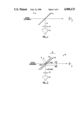
- FIG. 2 illustrates a HUD system according to one embodiment of the present invention utilizing dual cholesteric liquid crystal elements.
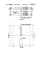
- FIG. 3(a) illustrate the transmission characteristics of a cholesteric liquid crystal element reflective to RHCP green light.
- FIG. 3(b) is a graph of transmission and polarization efficiency of a cholesteric liquid crystal element.
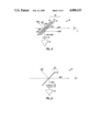
- FIG. 4 illustrates an HUD system according to one embodiment of the present invention utilizing dual cholesteric liquid crystal elements and a half-wave-length filter.
- FIG. 5 illustrates an HUD system according to another embodiment of the present invention utilizing a single cholesteric liquid crystal element and circular polarizing filter.
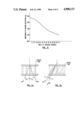
- FIG. 6 is a graph illustrating the angular dependence of the wavelength of maximum reflection.
- FIGS. 7(a) and 7(b) illustrate the biasing of the reflection angle from the cholesteric liquid crystal element through the use of surface tilt, untilted and tilted cases, respectively.
- HUD system 18 utilizing cholesteric liquid crystal combiner 20 according to the present invention, is shown.
- HUD system 18 includes combiner 20, together with an image source 22, and collimating optics 24.
- Combiner 20 in the preferred embodiment, comprises first and second cholesteric elements 26 and 28, respectively.
- First cholesteric liquid crystal element 26 is tuned to reflect right hand circular polarized (RHCP) light in a bandwidth, B, around 540 Nm (i..e, green light), and second cholesteric liquid crystal element 28 is tuned to reflect left hand circular polarized (LHCP) light in that same bandwidth, B. That is, first cholesteric liquid crystal element 26 is reflective to images that are RHCP and in the bandwidth B and transmissive to all other images, and second cholesteric liquid crystal element 28 is reflective to images that are LHCP and in the bandwidth B.
- First and second cholesteric elements 26, 28 are, in one embodiment, separate elements, and positioned roughly parallel to one another. However, other embodiments of the present invention will have first and second cholesteric elements 26, 28 joined as one element, or oriented a parallel to one another, dependent on the intended application.
- Image source 22 may be a cathode ray tube (CRT), liquid crystal display (LCD), or other type of display.
- image source 22 is capable of generating images of instrumentation, for example aircraft altitude, bearing, fuel reserve level, gun-sights, etc.
- Image source 22 is preferably a green CRT having a phosphor coating, P43 or P53 for example, with a narrow bandwith of transmission centered around 540 Nm.
- the brightness of image source 22 must be sufficient to be perceived by an observer, symbolized by an eye labelled O, after reflection, but due to the high reflectivity of a combiner constructed according to the present invention, the brightness of image source 22 may be kept to a minimum.
- Collimating optics 24 may consist of various lenses, etc., and will be arranged as a function of the relative positions of combiner 20, image source 22, and observer O. The effect of collimation is to focus the images from image source 22 at some distance in the line-of-sight plane of observer O. For aircraft HUD applications, a collimated focus between 40 feet and infinity is preferred.
- HUD system 18 is positioned in an aircraft cockpit, or similar location, such that combiner 20 lies between the outside environment and observer O, in the plane of the observer's line-of-sight.
- Collimating optics 24 are positioned between combiner 20 and image source 22.
- Image source 22 is positioned such that images generated thereby are incident on, and reflected by, combiner 20 into the line-of-sight plane of observer O.
- cholesteric liquid crystal elements may be beneficial.
- Cholesteric liquid crystals of the type employed in the present invention exhibit a number of unique properties with regard to light incident upon them. Specific to the present invention are several properties of such liquid crystals, explained with reference to FIGS. 3(a) and 3(b).
- a cholesteric liquid crystal element (or cholesteric element) is substantially transparent to all wavelengths of electromagnetic radiation, specifically visible light, except that within a narrow bandwidth, B, around a selected primary wavelength, for example 540 Nm (i.e., green), as shown in FIG. 3(a). Within bandwidth B, light of one rotary sense (LHCP or RHCP) incident upon the cholesteric element from either direction is reflected by the cholesteric element.
- LHCP or RHCP rotary sense
- a cholesteric element which is reflective to right-hand circular polarized light is said to be a right-hand circular polarized (or right-handed) cholesteric element.
- a cholesteric liquid crystal element which is reflective to left-hand circular polarized light is said to be a left-hand circular polarized (or left-handed) cholesteric element.
- RHCP light reflected by a cholesteric element maintains original rotary sense (i.e., does not change handedness).
- RHCP light reflected by a cholesteric element is reflected as RHCP light.
- RHCP light incident upon a reflective surface is reflected as LHCP light.
- cholesteric elements have very high transmissivity and reflectance around the primary wavelength.
- a cholesteric element is capable of achieving transmission of 90% for all light except that of one rotary sense within the bandwidth, B, around the primary wavelength, for which light the element is capable of 90% reflection.
- this provides the observer with acute visibility of images of the outside environment, transmitted through the cholesteric element, combined with high-contrast projected symbology, reflected off the element.
- HUD system 18 is positioned to receive images from the outside environment through combiner 20.
- Green light emitting from image source 22, of equal parts LHCP and RHCP, is collimated by collimating optics 24, and caused to be incident upon first cholesteric element 26.
- the RHCP portion of light incident upon first cholesteric element 26 is reflected into the line-of-sight plane of observer O, while the LHCP portion of the light is transmitted unattenuated by first cholesteric element 26 and caused to be incident upon second cholesteric element 28.
- the LHCP light incident upon second cholesteric element 28 is reflected into the line-of-sight plane of observer O by second cholesteric element 28, passing unattenuated through first cholesteric element 26.
- cholesteric elements exhibit high transmissivity, better viewing of images of the outside environment is provided. Further, since cholesteric elements are reflective to light within a selected bandwidth incident upon them from either direction, images from the outside environment within the reflective bandwidth are reflected away from observer O. Thus, the projected images within the bandwidth B have a higher contrast as against images from the outside environment. Consequently, image source 22 need be of a lower power than that used in the prior art. This lowers the cost and complexity of HUD system 18.
- HUD system 18' consists of an image source 32, similar to that described above, collimating optics 34, again as described above, and combiner 20', comprising first and second cholesteric elements 36 and 38 respectively. Between first and second cholesteric elements 36, 38 is positioned half wavelength filter 40. First and second cholesteric elements 36, 38 are formed to be RHCP, both having a bandwidth, B, of reflection centered around 540 Nm (green light). First and second cholesteric elements 36, 38, and halffl-wavelength filter 40 are positioned in the line-of-sight plane of observer O, and further in the path of incidence of image source 32.
- green light emitting from image source 32 is collimated by collimating optics 34 and caused to be incident upon first cholesteric element 36.
- RHCP light incident upon first cholesteric element 36 is reflected into the line-of-sight plane of observer O, while LHCP light is transmitted unattenuated by first cholesteric element 36 and caused to be incident upon half-wavelength filter 40.
- Light passing through half-wavelength filter 40 is caused to reverse its rotary sense (i.e., LHCP light is reversed to RHCP light).
- half-wavelength filter 40 Light passing through half-wavelength filter 40 is caused to be incident upon second cholesteric element 38, which reflects the now RHCP light into the line-of-sight plane of observer O. Intermediate to reaching observer O, the light reflected by second cholesteric element 38 passes once more through halfwavelength filter 40, undergoing a second reversal of rotary sense (i.e., RHCP to LHCP), so as to pass unattenuated through first cholesteric element 36 to observer O.
- RHCP to LHCP second reversal of rotary sense
- FIG. 4 Since the optical properties of a cholesteric element are directly dependent on the temperature of the cholesteric liquid crystal material, the embodiment as detailed above (FIG. 4) uses two identical cholesteric elements to minimize the effects of temperature shifts on the optical performance of the combiner. Properties such as the dependence of the reflected wavelength on the angle of incidence (further discussed below) can also be better controlled when identical cholesteric elements are used.
- an HUD system 18'' has a combiner 20'' comprised of a single cholesteric element 48, tuned to reflect green RHCP light, and located in the line-of-sight plane of observer O.
- HUD system 18'' further comprises image source 42, collimating optics 44, and circular polarizing filter 46. This embodiment is most commonly used in situations where image source 42 is provided with a polarizing filter to reduce reflection from external light, such as sunlight.
- image source 42 which is RHCP
- collimating optics 44 In operation, light emitting from image source 42, which is RHCP is collimated by collimating optics 44, and transmitted to cholesteric element 48 by circular polarizing filter 46.
- Light which is LHCP is substantially entirely filtered out by circular polarizing filter 46.
- images projected upon cholesteric element 48 by image source 42 are predominantly RHCP, and consequently reflected by cholesteric element 48 so as to be combined with images passing through cholesteric element 48 from the outside environment.
- the composition of the cholesteric combiner may be such that it has a bandwidth of maximum reflection centered at a wavelength other than 540 Nm.
- the bandwidth of maximum reflection around the primary wavelength may be varied as a function of the cholesteric liquid crystal's composition.
- the physical arrangement of components of the invention may be varied with specific results. For example, relying on another property of cholesteric elements, as demonstrated in FIG. 6, that the wavelength of maximum reflection is angular sensitive (i.e., as the angle of incidence increases, the wavelength of maximum reflection is shifted toward the shorter wavelengths) the wavelength of maximum reflection of the cholesteric liquid crystal element for normally incident light may be increased to compensate for the shift toward the shorter wavelengths of reflection for non-normally incident light.
- cholesteric elements Another property of cholesteric elements, demonstrated in FIGS. 7(a) and 7(b), is that the separation between the angle of incidence i and angle of reflection r is a function of the orientation, or tilt, of the helical axis of the cholesteric layer. As the helical axis of the cholesteric layer. As the helical axis is tilted away from normal to the surface of the cholesteric liquid crystal element the separation becomes smaller. Thus, positioning of the reflected image in the line-of-sight of the observer may be controlled by the composition of the element (as opposed to positioning of the image source).
Abstract
Description
Claims (9)
Priority Applications (1)
| Application Number | Priority Date | Filing Date | Title |
|---|---|---|---|
| US07/263,149 US4900133A (en) | 1988-10-27 | 1988-10-27 | Heads-up display combiner utilizing a cholesteric liquid crystal element |
Applications Claiming Priority (1)
| Application Number | Priority Date | Filing Date | Title |
|---|---|---|---|
| US07/263,149 US4900133A (en) | 1988-10-27 | 1988-10-27 | Heads-up display combiner utilizing a cholesteric liquid crystal element |
Publications (1)
| Publication Number | Publication Date |
|---|---|
| US4900133A true US4900133A (en) | 1990-02-13 |
Family
ID=23000583
Family Applications (1)
| Application Number | Title | Priority Date | Filing Date |
|---|---|---|---|
| US07/263,149 Expired - Lifetime US4900133A (en) | 1988-10-27 | 1988-10-27 | Heads-up display combiner utilizing a cholesteric liquid crystal element |
Country Status (1)
| Country | Link |
|---|---|
| US (1) | US4900133A (en) |
Cited By (69)
| Publication number | Priority date | Publication date | Assignee | Title |
|---|---|---|---|---|
| US5015188A (en) * | 1988-05-03 | 1991-05-14 | The United States Of America As Represented By The Secretary Of The Air Force | Three dimensional tactical element situation (3DTES) display |
| US5050966A (en) * | 1988-07-06 | 1991-09-24 | Kaiser Aerospace & Electronics Corporation | Optical combiner collimating apparatus |
| FR2681702A1 (en) * | 1991-09-24 | 1993-03-26 | Renault | Device for displaying information by projection |
| US5235443A (en) * | 1989-07-10 | 1993-08-10 | Hoffmann-La Roche Inc. | Polarizer device |
| US5293513A (en) * | 1990-05-30 | 1994-03-08 | Mitsubishi Denki Kabushiki Kaisha | Switching system for automotive vehicle including a reflector positioned below a sight line of a driver |
| US5343313A (en) * | 1990-03-20 | 1994-08-30 | James L. Fergason | Eye protection system with heads up display |
| US5408346A (en) * | 1993-10-20 | 1995-04-18 | Kaiser Electro-Optics, Inc. | Optical collimating device employing cholesteric liquid crystal and a non-transmissive reflector |
| US5418631A (en) * | 1993-05-14 | 1995-05-23 | Kaiser Optical Systems, Inc. | Edge-lit holographic diffusers for flat-panel displays |
| US5421589A (en) * | 1993-05-14 | 1995-06-06 | The Walt Disney Company | Method and apparatus for displaying an alpha channel virtual image |
| US5526022A (en) | 1993-01-06 | 1996-06-11 | Virtual I/O, Inc. | Sourceless orientation sensor |
| US5541745A (en) * | 1994-01-25 | 1996-07-30 | Fergason; James L. | Illumination system for a display using cholesteric liquid crystal reflectors |
| US5552935A (en) * | 1988-07-01 | 1996-09-03 | Robert Bosch Gmbh | Head-up display device for motor vehicles |
| WO1996038319A2 (en) | 1995-05-22 | 1996-12-05 | Donnelly Corporation | Rearview vision system for vehicle including panoramic view |
| US5585967A (en) * | 1993-09-07 | 1996-12-17 | The Walt Disney Company | Three dimensional virtual image system |
| US5619377A (en) * | 1992-02-07 | 1997-04-08 | Virtual I/O, Inc. | Optically corrected helmet mounted display |
| US5644323A (en) * | 1994-12-21 | 1997-07-01 | Siliscape, Inc. | Miniature synthesized virtual image electronic display |
| US5694230A (en) * | 1995-06-07 | 1997-12-02 | Digital Optics Corp. | Diffractive optical elements as combiners |
| US5767820A (en) * | 1995-05-09 | 1998-06-16 | Virtual Research Systems | Head-mounted visual display apparatus |
| US5771124A (en) * | 1996-07-02 | 1998-06-23 | Siliscape | Compact display system with two stage magnification and immersed beam splitter |
| US5790209A (en) * | 1994-11-10 | 1998-08-04 | Northrop Grumman Corporation | Canopy transmittal reflectance control and information display |
| US5828495A (en) * | 1997-07-31 | 1998-10-27 | Eastman Kodak Company | Lenticular image displays with extended depth |
| US5859714A (en) * | 1993-11-16 | 1999-01-12 | Asahi Glass Company, Ltd. | Head-up display, a combiner used for the head-up display and a method of designing the head-up display |
| US5864326A (en) * | 1992-02-07 | 1999-01-26 | I-O Display Systems Llc | Depixelated visual display |
| US5870068A (en) * | 1994-12-21 | 1999-02-09 | Siliscape, Inc. | Twice folded compound magnified virtual image electronic display |
| US5903396A (en) * | 1997-10-17 | 1999-05-11 | I/O Display Systems, Llc | Intensified visual display |
| US5903395A (en) * | 1994-08-31 | 1999-05-11 | I-O Display Systems Llc | Personal visual display system |
| US5991087A (en) * | 1993-11-12 | 1999-11-23 | I-O Display System Llc | Non-orthogonal plate in a virtual reality or heads up display |
| US5991085A (en) | 1995-04-21 | 1999-11-23 | I-O Display Systems Llc | Head-mounted personal visual display apparatus with image generator and holder |
| US6097543A (en) * | 1992-02-07 | 2000-08-01 | I-O Display Systems Llc | Personal visual display |
| US6101431A (en) * | 1997-08-28 | 2000-08-08 | Kawasaki Jukogyo Kabushiki Kaisha | Flight system and system for forming virtual images for aircraft |
| US6160666A (en) * | 1994-02-07 | 2000-12-12 | I-O Display Systems Llc | Personal visual display system |
| WO2001016640A2 (en) * | 1999-08-12 | 2001-03-08 | Honeywell, Inc. | Variable immersion vignetting display |
| US6307604B1 (en) * | 1992-07-04 | 2001-10-23 | U.S. Philips Corporation | Light source having a luminescent layer |
| WO2001084522A2 (en) * | 2000-04-28 | 2001-11-08 | L-3 Communications Corporation | Head-up display simulator system |
| US6404557B2 (en) | 1999-09-10 | 2002-06-11 | Inviso, Inc. | Display illumination system |
| WO2002086591A1 (en) * | 2001-04-23 | 2002-10-31 | Reveo, Inc. | Image display system and electrically actuatable image combiner therefor |
| US6639569B2 (en) | 2000-12-14 | 2003-10-28 | Ford Global Technologies, Llc | Integrated heads-up display and cluster projection panel assembly for motor vehicles |
| US20040008412A1 (en) * | 2002-05-22 | 2004-01-15 | Yingqlu Jiang | Real image configuration for a high efficiency heads-up display (HUD) using a polarizing mirror and a polarization preserving screen |
| US20040135742A1 (en) * | 2002-12-31 | 2004-07-15 | Weber Michael F. | Head-up display with polarized light source and wide-angle p-polarization reflective polarizer |
| US20050140573A1 (en) * | 2003-12-01 | 2005-06-30 | Andrew Riser | Image display system and method for head-supported viewing system |
| US7095562B1 (en) | 2004-09-27 | 2006-08-22 | Rockwell Collins, Inc. | Advanced compact head up display |
| US20070279755A1 (en) * | 2006-06-01 | 2007-12-06 | 3M Innovative Properties Company | Head-Up Display System |
| US7397606B1 (en) | 2005-08-04 | 2008-07-08 | Rockwell Collins, Inc. | Meniscus head up display combiner |
| US7513668B1 (en) | 2005-08-04 | 2009-04-07 | Rockwell Collins, Inc. | Illumination system for a head up display |
| US20100066925A1 (en) * | 2008-09-18 | 2010-03-18 | Kabushiki Kaisha Toshiba | Head Up Display |
| US8593521B2 (en) | 2004-04-15 | 2013-11-26 | Magna Electronics Inc. | Imaging system for vehicle |
| US8599001B2 (en) | 1993-02-26 | 2013-12-03 | Magna Electronics Inc. | Vehicular vision system |
| US8629768B2 (en) | 1999-08-12 | 2014-01-14 | Donnelly Corporation | Vehicle vision system |
| US8636393B2 (en) | 2006-08-11 | 2014-01-28 | Magna Electronics Inc. | Driver assistance system for vehicle |
| US8637801B2 (en) | 1996-03-25 | 2014-01-28 | Magna Electronics Inc. | Driver assistance system for a vehicle |
| US8643724B2 (en) | 1996-05-22 | 2014-02-04 | Magna Electronics Inc. | Multi-camera vision system for a vehicle |
| US20140055865A1 (en) * | 2012-08-21 | 2014-02-27 | Commissariat A L'energie Atomique Et Aux Energies Alternatives | Compact head-up display |
| US8665079B2 (en) | 2002-05-03 | 2014-03-04 | Magna Electronics Inc. | Vision system for vehicle |
| EP2776885A1 (en) * | 2011-11-07 | 2014-09-17 | Elbit Systems of America, LLC | System and method for projecting synthetic imagery and scenic imagery using an optical component comprising a diffractive optical element pattern |
| DE102013206505A1 (en) * | 2013-04-12 | 2014-10-16 | Bayerische Motoren Werke Aktiengesellschaft | Translucent glass for displaying an image of a polarized sunglass head-up display |
| US8886401B2 (en) | 2003-10-14 | 2014-11-11 | Donnelly Corporation | Driver assistance system for a vehicle |
| US8977008B2 (en) | 2004-09-30 | 2015-03-10 | Donnelly Corporation | Driver assistance system for vehicle |
| US9014904B2 (en) | 2004-12-23 | 2015-04-21 | Magna Electronics Inc. | Driver assistance system for vehicle |
| TWI490547B (en) * | 2013-05-07 | 2015-07-01 | Shinyoptics Corp | Autofocus head mounted display |
| US9191574B2 (en) | 2001-07-31 | 2015-11-17 | Magna Electronics Inc. | Vehicular vision system |
| US9329388B1 (en) | 2011-04-28 | 2016-05-03 | Google Inc. | Heads-up display for a large transparent substrate |
| US20160216414A1 (en) * | 2013-10-03 | 2016-07-28 | Fujifilm Corporation | Half mirror for displaying projected image, method for producing same, and projected image display system |
| US20170110023A1 (en) * | 2015-10-20 | 2017-04-20 | The Boeing Company | Systems and methods for providing a virtual heads up display in a vehicle simulator |
| CN107209389A (en) * | 2015-02-20 | 2017-09-26 | 富士胶片株式会社 | windshield and head-up display system |
| JP6238151B1 (en) * | 2016-03-24 | 2017-11-29 | パナソニックIpマネジメント株式会社 | Head-up display device and vehicle |
| WO2018025741A1 (en) * | 2016-08-05 | 2018-02-08 | パナソニックIpマネジメント株式会社 | Combiner and head-up display device using same |
| US9900522B2 (en) | 2010-12-01 | 2018-02-20 | Magna Electronics Inc. | System and method of establishing a multi-camera image using pixel remapping |
| US20190197926A1 (en) * | 2016-10-18 | 2019-06-27 | Boe Technology Group Co., Ltd. | Display device and intelligent floor |
| US10793067B2 (en) | 2011-07-26 | 2020-10-06 | Magna Electronics Inc. | Imaging system for vehicle |
Citations (18)
| Publication number | Priority date | Publication date | Assignee | Title |
|---|---|---|---|---|
| US3679290A (en) * | 1971-01-06 | 1972-07-25 | Xerox Corp | Liquid crystal optical filter system |
| US3697154A (en) * | 1971-05-12 | 1972-10-10 | Us Navy | Optical viewing system |
| US3711181A (en) * | 1971-03-05 | 1973-01-16 | Xerox Corp | Optical notch filter |
| GB1321303A (en) * | 1970-03-31 | 1973-06-27 | Pilkington Perkin Elmer Ltd | Optical systems |
| US3915548A (en) * | 1973-04-30 | 1975-10-28 | Hughes Aircraft Co | Holographic lens and liquid crystal image source for head-up display |
| US3957348A (en) * | 1975-03-26 | 1976-05-18 | Xerox Corporation | Method for altering elliptically polarized light |
| US4026641A (en) * | 1975-12-30 | 1977-05-31 | The United States Of America As Represented By The Secretary Of The Army | Toric reflector display |
| GB1529227A (en) * | 1976-09-03 | 1978-10-18 | British Aircraft Corp Ltd | Optical viewing systems |
| US4269475A (en) * | 1978-10-05 | 1981-05-26 | Elliott Brothers (London) Limited | Head-up displays |
| US4398799A (en) * | 1980-03-04 | 1983-08-16 | Pilkington P.E. Limited | Head-up displays |
| US4407564A (en) * | 1980-01-22 | 1983-10-04 | Elliott Brothers (London) Limited | Head-up displays |
| US4447128A (en) * | 1982-12-03 | 1984-05-08 | Hughes Aircraft Company | Diffraction head up display solar radiation filter |
| GB2149140A (en) * | 1983-10-31 | 1985-06-05 | Gec Avionics | Head-up display systems |
| EP0154953A2 (en) * | 1984-03-12 | 1985-09-18 | Matsushita Electric Industrial Co., Ltd. | Optical filter and the method of preparing the same |
| US4582394A (en) * | 1982-06-22 | 1986-04-15 | Pilkington P.E. Limited | Display apparatus |
| US4600271A (en) * | 1983-03-07 | 1986-07-15 | Thomson Csf | Head-up display |
| US4611877A (en) * | 1984-08-31 | 1986-09-16 | Gec Avionics Limited | Optical projectors for head up displays |
| US4613200A (en) * | 1984-07-09 | 1986-09-23 | Ford Motor Company | Heads-up display system with holographic dispersion correcting |
-
1988
- 1988-10-27 US US07/263,149 patent/US4900133A/en not_active Expired - Lifetime
Patent Citations (19)
| Publication number | Priority date | Publication date | Assignee | Title |
|---|---|---|---|---|
| GB1321303A (en) * | 1970-03-31 | 1973-06-27 | Pilkington Perkin Elmer Ltd | Optical systems |
| US3679290A (en) * | 1971-01-06 | 1972-07-25 | Xerox Corp | Liquid crystal optical filter system |
| US3711181A (en) * | 1971-03-05 | 1973-01-16 | Xerox Corp | Optical notch filter |
| US3697154A (en) * | 1971-05-12 | 1972-10-10 | Us Navy | Optical viewing system |
| US3915548A (en) * | 1973-04-30 | 1975-10-28 | Hughes Aircraft Co | Holographic lens and liquid crystal image source for head-up display |
| US3957348A (en) * | 1975-03-26 | 1976-05-18 | Xerox Corporation | Method for altering elliptically polarized light |
| US4026641A (en) * | 1975-12-30 | 1977-05-31 | The United States Of America As Represented By The Secretary Of The Army | Toric reflector display |
| GB1529227A (en) * | 1976-09-03 | 1978-10-18 | British Aircraft Corp Ltd | Optical viewing systems |
| US4269475A (en) * | 1978-10-05 | 1981-05-26 | Elliott Brothers (London) Limited | Head-up displays |
| US4407564A (en) * | 1980-01-22 | 1983-10-04 | Elliott Brothers (London) Limited | Head-up displays |
| US4398799A (en) * | 1980-03-04 | 1983-08-16 | Pilkington P.E. Limited | Head-up displays |
| US4582394A (en) * | 1982-06-22 | 1986-04-15 | Pilkington P.E. Limited | Display apparatus |
| US4447128A (en) * | 1982-12-03 | 1984-05-08 | Hughes Aircraft Company | Diffraction head up display solar radiation filter |
| US4600271A (en) * | 1983-03-07 | 1986-07-15 | Thomson Csf | Head-up display |
| GB2149140A (en) * | 1983-10-31 | 1985-06-05 | Gec Avionics | Head-up display systems |
| EP0154953A2 (en) * | 1984-03-12 | 1985-09-18 | Matsushita Electric Industrial Co., Ltd. | Optical filter and the method of preparing the same |
| US4613200A (en) * | 1984-07-09 | 1986-09-23 | Ford Motor Company | Heads-up display system with holographic dispersion correcting |
| US4611877A (en) * | 1984-08-31 | 1986-09-16 | Gec Avionics Limited | Optical projectors for head up displays |
| US4611877C1 (en) * | 1984-08-31 | 2002-09-17 | Bae Sys Electronics Ltd | Optical projectors for head up displays |
Non-Patent Citations (18)
| Title |
|---|
| "Holographic `Mirror` Helps Fighter Pilots to See", Engineering Materials Design, vol. 31, No. 4, Apr. 1987; p. 15. |
| D. M. Makow, "Peak Reflectance & Color Gamut of Superimposed Left- and Right-Handed Cholesteric Liquid Crystals", Applied Optics, vol. 19, No. 8, 4/15/1980. |
| D. M. Makow, Peak Reflectance & Color Gamut of Superimposed Left and Right Handed Cholesteric Liquid Crystals , Applied Optics, vol. 19, No. 8, 4/15/1980. * |
| Holographic Mirror Helps Fighter Pilots to See , Engineering Materials Design, vol. 31, No. 4, Apr. 1987; p. 15. * |
| IBM Technical Disclosure Bulletin, "Light Beam Combiner", vol. 15, No. 4, Sep. 1972. |
| IBM Technical Disclosure Bulletin, Light Beam Combiner , vol. 15, No. 4, Sep. 1972. * |
| J. Adams et al., "Cholesteric Films as Optical Filters", Journal of Applied Physics, vol. 42, No. 10, Sep. 1971. |
| J. Adams et al., Cholesteric Films as Optical Filters , Journal of Applied Physics, vol. 42, No. 10, Sep. 1971. * |
| Jenkins & White, "Fundamentals of Optics", p. 567, McGraw-Hill, 1976. |
| Jenkins & White, Fundamentals of Optics , p. 567, McGraw Hill, 1976. * |
| Kahn, "Cholesteric Liquid Crystals for Optical Application", Appl. Phys. Letters, vol. 18, No. 6, Mar. 15, 1971, pp. 231-233. |
| Kahn, Cholesteric Liquid Crystals for Optical Application , Appl. Phys. Letters, vol. 18, No. 6, Mar. 15, 1971, pp. 231 233. * |
| Melamed et al., "Selected Optical Properties of Mixtures of Cholesteric Liquid Crystal", Applied Optics, vol. 10, No. 5, May 1971. |
| Melamed et al., Selected Optical Properties of Mixtures of Cholesteric Liquid Crystal , Applied Optics, vol. 10, No. 5, May 1971. * |
| P. G. deGennes, "The Physics of Liquid Crystals", chapter 1 titled Anisotropic Fluids: Main Types & Properties, Clanedon Press, 1974. |
| P. G. deGennes, The Physics of Liquid Crystals , chapter 1 titled Anisotropic Fluids: Main Types & Properties, Clanedon Press, 1974. * |
| W. A. Shurcliff, "Polarized Light", chapter titled Retarders and Circular Polarizers, Harvard University Press, 1962. |
| W. A. Shurcliff, Polarized Light , chapter titled Retarders and Circular Polarizers, Harvard University Press, 1962. * |
Cited By (153)
| Publication number | Priority date | Publication date | Assignee | Title |
|---|---|---|---|---|
| US5015188A (en) * | 1988-05-03 | 1991-05-14 | The United States Of America As Represented By The Secretary Of The Air Force | Three dimensional tactical element situation (3DTES) display |
| US5552935A (en) * | 1988-07-01 | 1996-09-03 | Robert Bosch Gmbh | Head-up display device for motor vehicles |
| US5566025A (en) * | 1988-07-01 | 1996-10-15 | Robert Bosch Gmbh | Head-up display device for motor vehicles |
| US5050966A (en) * | 1988-07-06 | 1991-09-24 | Kaiser Aerospace & Electronics Corporation | Optical combiner collimating apparatus |
| US5235443A (en) * | 1989-07-10 | 1993-08-10 | Hoffmann-La Roche Inc. | Polarizer device |
| US5295009A (en) * | 1989-07-10 | 1994-03-15 | Hoffmann-La Roche | Polarizer device |
| US5343313A (en) * | 1990-03-20 | 1994-08-30 | James L. Fergason | Eye protection system with heads up display |
| US5293513A (en) * | 1990-05-30 | 1994-03-08 | Mitsubishi Denki Kabushiki Kaisha | Switching system for automotive vehicle including a reflector positioned below a sight line of a driver |
| FR2681702A1 (en) * | 1991-09-24 | 1993-03-26 | Renault | Device for displaying information by projection |
| US5864326A (en) * | 1992-02-07 | 1999-01-26 | I-O Display Systems Llc | Depixelated visual display |
| US6097543A (en) * | 1992-02-07 | 2000-08-01 | I-O Display Systems Llc | Personal visual display |
| US5949583A (en) * | 1992-02-07 | 1999-09-07 | I-O Display Systems Llc | Head-mounted display with image generator, fold mirror and mirror for transmission to the eye position of the user |
| US5642227A (en) * | 1992-02-07 | 1997-06-24 | Virtual I/O, Inc. | Optical correction for virtual reality and heads up displays |
| US5673151A (en) * | 1992-02-07 | 1997-09-30 | Virtual I/O | Image correction in virtual reality and heads up displays |
| US5619377A (en) * | 1992-02-07 | 1997-04-08 | Virtual I/O, Inc. | Optically corrected helmet mounted display |
| US6307604B1 (en) * | 1992-07-04 | 2001-10-23 | U.S. Philips Corporation | Light source having a luminescent layer |
| US5526022A (en) | 1993-01-06 | 1996-06-11 | Virtual I/O, Inc. | Sourceless orientation sensor |
| US8599001B2 (en) | 1993-02-26 | 2013-12-03 | Magna Electronics Inc. | Vehicular vision system |
| US8917169B2 (en) | 1993-02-26 | 2014-12-23 | Magna Electronics Inc. | Vehicular vision system |
| US5421589A (en) * | 1993-05-14 | 1995-06-06 | The Walt Disney Company | Method and apparatus for displaying an alpha channel virtual image |
| US5418631A (en) * | 1993-05-14 | 1995-05-23 | Kaiser Optical Systems, Inc. | Edge-lit holographic diffusers for flat-panel displays |
| US5585967A (en) * | 1993-09-07 | 1996-12-17 | The Walt Disney Company | Three dimensional virtual image system |
| US5408346A (en) * | 1993-10-20 | 1995-04-18 | Kaiser Electro-Optics, Inc. | Optical collimating device employing cholesteric liquid crystal and a non-transmissive reflector |
| US5991087A (en) * | 1993-11-12 | 1999-11-23 | I-O Display System Llc | Non-orthogonal plate in a virtual reality or heads up display |
| US5859714A (en) * | 1993-11-16 | 1999-01-12 | Asahi Glass Company, Ltd. | Head-up display, a combiner used for the head-up display and a method of designing the head-up display |
| US5541745A (en) * | 1994-01-25 | 1996-07-30 | Fergason; James L. | Illumination system for a display using cholesteric liquid crystal reflectors |
| US6160666A (en) * | 1994-02-07 | 2000-12-12 | I-O Display Systems Llc | Personal visual display system |
| US5903395A (en) * | 1994-08-31 | 1999-05-11 | I-O Display Systems Llc | Personal visual display system |
| US5790209A (en) * | 1994-11-10 | 1998-08-04 | Northrop Grumman Corporation | Canopy transmittal reflectance control and information display |
| US5793450A (en) * | 1994-11-10 | 1998-08-11 | Grumman Aerospace Corporation | Canopy transmittal reflectance control and information display |
| US5973845A (en) * | 1994-12-21 | 1999-10-26 | Hildebrand; Alfred P. | Miniature synthesized virtual image electronic display |
| US5644323A (en) * | 1994-12-21 | 1997-07-01 | Siliscape, Inc. | Miniature synthesized virtual image electronic display |
| US5905478A (en) * | 1994-12-21 | 1999-05-18 | Siliscape, Inc. | Twice folded compound magnified virtual image electronic display |
| US5870068A (en) * | 1994-12-21 | 1999-02-09 | Siliscape, Inc. | Twice folded compound magnified virtual image electronic display |
| US6603443B1 (en) | 1994-12-21 | 2003-08-05 | Three-Five Systems, Inc. | Compact display system controlled by eye position sensory system |
| US5838498A (en) * | 1994-12-21 | 1998-11-17 | Siliscape, Inc. | Miniature synthesized virtual image electronic display |
| US5991085A (en) | 1995-04-21 | 1999-11-23 | I-O Display Systems Llc | Head-mounted personal visual display apparatus with image generator and holder |
| US5767820A (en) * | 1995-05-09 | 1998-06-16 | Virtual Research Systems | Head-mounted visual display apparatus |
| WO1996038319A2 (en) | 1995-05-22 | 1996-12-05 | Donnelly Corporation | Rearview vision system for vehicle including panoramic view |
| US6005714A (en) * | 1995-06-07 | 1999-12-21 | Digital Optics Corporation | Two layer optical elements |
| US5694230A (en) * | 1995-06-07 | 1997-12-02 | Digital Optics Corp. | Diffractive optical elements as combiners |
| US8637801B2 (en) | 1996-03-25 | 2014-01-28 | Magna Electronics Inc. | Driver assistance system for a vehicle |
| US8993951B2 (en) | 1996-03-25 | 2015-03-31 | Magna Electronics Inc. | Driver assistance system for a vehicle |
| US8643724B2 (en) | 1996-05-22 | 2014-02-04 | Magna Electronics Inc. | Multi-camera vision system for a vehicle |
| US8842176B2 (en) | 1996-05-22 | 2014-09-23 | Donnelly Corporation | Automatic vehicle exterior light control |
| US9131120B2 (en) | 1996-05-22 | 2015-09-08 | Magna Electronics Inc. | Multi-camera vision system for a vehicle |
| US5771124A (en) * | 1996-07-02 | 1998-06-23 | Siliscape | Compact display system with two stage magnification and immersed beam splitter |
| US5959781A (en) * | 1996-07-02 | 1999-09-28 | Inviso | Optical method employing total internal reflection |
| US6433935B2 (en) | 1996-07-02 | 2002-08-13 | Three-Five Systems, Inc. | Display illumination system |
| US6055110A (en) * | 1996-07-02 | 2000-04-25 | Inviso, Inc. | Compact display system controlled by eye position sensor system |
| US5828495A (en) * | 1997-07-31 | 1998-10-27 | Eastman Kodak Company | Lenticular image displays with extended depth |
| US6101431A (en) * | 1997-08-28 | 2000-08-08 | Kawasaki Jukogyo Kabushiki Kaisha | Flight system and system for forming virtual images for aircraft |
| US5903396A (en) * | 1997-10-17 | 1999-05-11 | I/O Display Systems, Llc | Intensified visual display |
| US9436880B2 (en) | 1999-08-12 | 2016-09-06 | Magna Electronics Inc. | Vehicle vision system |
| US6456438B1 (en) | 1999-08-12 | 2002-09-24 | Honeywell Inc. | Variable immersion vignetting display |
| US8629768B2 (en) | 1999-08-12 | 2014-01-14 | Donnelly Corporation | Vehicle vision system |
| WO2001016640A2 (en) * | 1999-08-12 | 2001-03-08 | Honeywell, Inc. | Variable immersion vignetting display |
| WO2001016640A3 (en) * | 1999-08-12 | 2001-09-20 | Allied Signal Inc | Variable immersion vignetting display |
| US6404557B2 (en) | 1999-09-10 | 2002-06-11 | Inviso, Inc. | Display illumination system |
| US6612840B1 (en) * | 2000-04-28 | 2003-09-02 | L-3 Communications Corporation | Head-up display simulator system |
| WO2001084522A2 (en) * | 2000-04-28 | 2001-11-08 | L-3 Communications Corporation | Head-up display simulator system |
| WO2001084522A3 (en) * | 2000-04-28 | 2002-03-07 | L 3 Comm Corp | Head-up display simulator system |
| US6639569B2 (en) | 2000-12-14 | 2003-10-28 | Ford Global Technologies, Llc | Integrated heads-up display and cluster projection panel assembly for motor vehicles |
| US6844980B2 (en) * | 2001-04-23 | 2005-01-18 | Reveo, Inc. | Image display system and electrically actuatable image combiner therefor |
| WO2002086591A1 (en) * | 2001-04-23 | 2002-10-31 | Reveo, Inc. | Image display system and electrically actuatable image combiner therefor |
| US20020171940A1 (en) * | 2001-04-23 | 2002-11-21 | Zhan He | Image display system and electrically actuatable image combiner therefor |
| US9191574B2 (en) | 2001-07-31 | 2015-11-17 | Magna Electronics Inc. | Vehicular vision system |
| US9376060B2 (en) | 2001-07-31 | 2016-06-28 | Magna Electronics Inc. | Driver assist system for vehicle |
| US9656608B2 (en) | 2001-07-31 | 2017-05-23 | Magna Electronics Inc. | Driver assist system for vehicle |
| US9834142B2 (en) | 2001-07-31 | 2017-12-05 | Magna Electronics Inc. | Driving assist system for vehicle |
| US10046702B2 (en) | 2001-07-31 | 2018-08-14 | Magna Electronics Inc. | Control system for vehicle |
| US10611306B2 (en) | 2001-07-31 | 2020-04-07 | Magna Electronics Inc. | Video processor module for vehicle |
| US8665079B2 (en) | 2002-05-03 | 2014-03-04 | Magna Electronics Inc. | Vision system for vehicle |
| US9643605B2 (en) | 2002-05-03 | 2017-05-09 | Magna Electronics Inc. | Vision system for vehicle |
| US11203340B2 (en) | 2002-05-03 | 2021-12-21 | Magna Electronics Inc. | Vehicular vision system using side-viewing camera |
| US10683008B2 (en) | 2002-05-03 | 2020-06-16 | Magna Electronics Inc. | Vehicular driving assist system using forward-viewing camera |
| US10351135B2 (en) | 2002-05-03 | 2019-07-16 | Magna Electronics Inc. | Vehicular control system using cameras and radar sensor |
| US10118618B2 (en) | 2002-05-03 | 2018-11-06 | Magna Electronics Inc. | Vehicular control system using cameras and radar sensor |
| US9834216B2 (en) | 2002-05-03 | 2017-12-05 | Magna Electronics Inc. | Vehicular control system using cameras and radar sensor |
| US9171217B2 (en) | 2002-05-03 | 2015-10-27 | Magna Electronics Inc. | Vision system for vehicle |
| US9555803B2 (en) | 2002-05-03 | 2017-01-31 | Magna Electronics Inc. | Driver assistance system for vehicle |
| US20040008412A1 (en) * | 2002-05-22 | 2004-01-15 | Yingqlu Jiang | Real image configuration for a high efficiency heads-up display (HUD) using a polarizing mirror and a polarization preserving screen |
| US7203005B2 (en) * | 2002-05-22 | 2007-04-10 | Chelix Technologies, Inc. | Real image configuration for a high efficiency heads-up display (HUD) using a polarizing mirror and a polarization preserving screen |
| US20040135742A1 (en) * | 2002-12-31 | 2004-07-15 | Weber Michael F. | Head-up display with polarized light source and wide-angle p-polarization reflective polarizer |
| US20050270655A1 (en) * | 2002-12-31 | 2005-12-08 | 3M Innovative Properties Company | Head-up display with narrow band reflective polarizer |
| US7123418B2 (en) | 2002-12-31 | 2006-10-17 | 3M Innovative Properties Company | Head-up display with narrow band reflective polarizer |
| US6952312B2 (en) | 2002-12-31 | 2005-10-04 | 3M Innovative Properties Company | Head-up display with polarized light source and wide-angle p-polarization reflective polarizer |
| US8886401B2 (en) | 2003-10-14 | 2014-11-11 | Donnelly Corporation | Driver assistance system for a vehicle |
| US20050140573A1 (en) * | 2003-12-01 | 2005-06-30 | Andrew Riser | Image display system and method for head-supported viewing system |
| US8818042B2 (en) | 2004-04-15 | 2014-08-26 | Magna Electronics Inc. | Driver assistance system for vehicle |
| US11503253B2 (en) | 2004-04-15 | 2022-11-15 | Magna Electronics Inc. | Vehicular control system with traffic lane detection |
| US10462426B2 (en) | 2004-04-15 | 2019-10-29 | Magna Electronics Inc. | Vehicular control system |
| US8593521B2 (en) | 2004-04-15 | 2013-11-26 | Magna Electronics Inc. | Imaging system for vehicle |
| US9008369B2 (en) | 2004-04-15 | 2015-04-14 | Magna Electronics Inc. | Vision system for vehicle |
| US9191634B2 (en) | 2004-04-15 | 2015-11-17 | Magna Electronics Inc. | Vision system for vehicle |
| US10015452B1 (en) | 2004-04-15 | 2018-07-03 | Magna Electronics Inc. | Vehicular control system |
| US10110860B1 (en) | 2004-04-15 | 2018-10-23 | Magna Electronics Inc. | Vehicular control system |
| US9609289B2 (en) | 2004-04-15 | 2017-03-28 | Magna Electronics Inc. | Vision system for vehicle |
| US11847836B2 (en) | 2004-04-15 | 2023-12-19 | Magna Electronics Inc. | Vehicular control system with road curvature determination |
| US9948904B2 (en) | 2004-04-15 | 2018-04-17 | Magna Electronics Inc. | Vision system for vehicle |
| US10735695B2 (en) | 2004-04-15 | 2020-08-04 | Magna Electronics Inc. | Vehicular control system with traffic lane detection |
| US9428192B2 (en) | 2004-04-15 | 2016-08-30 | Magna Electronics Inc. | Vision system for vehicle |
| US10187615B1 (en) | 2004-04-15 | 2019-01-22 | Magna Electronics Inc. | Vehicular control system |
| US9736435B2 (en) | 2004-04-15 | 2017-08-15 | Magna Electronics Inc. | Vision system for vehicle |
| US10306190B1 (en) | 2004-04-15 | 2019-05-28 | Magna Electronics Inc. | Vehicular control system |
| US7619825B1 (en) | 2004-09-27 | 2009-11-17 | Rockwell Collins, Inc. | Compact head up display with wide viewing angle |
| US7095562B1 (en) | 2004-09-27 | 2006-08-22 | Rockwell Collins, Inc. | Advanced compact head up display |
| US10623704B2 (en) | 2004-09-30 | 2020-04-14 | Donnelly Corporation | Driver assistance system for vehicle |
| US8977008B2 (en) | 2004-09-30 | 2015-03-10 | Donnelly Corporation | Driver assistance system for vehicle |
| US10509972B2 (en) | 2004-12-23 | 2019-12-17 | Magna Electronics Inc. | Vehicular vision system |
| US9940528B2 (en) | 2004-12-23 | 2018-04-10 | Magna Electronics Inc. | Driver assistance system for vehicle |
| US11308720B2 (en) | 2004-12-23 | 2022-04-19 | Magna Electronics Inc. | Vehicular imaging system |
| US9193303B2 (en) | 2004-12-23 | 2015-11-24 | Magna Electronics Inc. | Driver assistance system for vehicle |
| US9014904B2 (en) | 2004-12-23 | 2015-04-21 | Magna Electronics Inc. | Driver assistance system for vehicle |
| US7397606B1 (en) | 2005-08-04 | 2008-07-08 | Rockwell Collins, Inc. | Meniscus head up display combiner |
| US7513668B1 (en) | 2005-08-04 | 2009-04-07 | Rockwell Collins, Inc. | Illumination system for a head up display |
| US20070279755A1 (en) * | 2006-06-01 | 2007-12-06 | 3M Innovative Properties Company | Head-Up Display System |
| US10071676B2 (en) | 2006-08-11 | 2018-09-11 | Magna Electronics Inc. | Vision system for vehicle |
| US11148583B2 (en) | 2006-08-11 | 2021-10-19 | Magna Electronics Inc. | Vehicular forward viewing image capture system |
| US11951900B2 (en) | 2006-08-11 | 2024-04-09 | Magna Electronics Inc. | Vehicular forward viewing image capture system |
| US10787116B2 (en) | 2006-08-11 | 2020-09-29 | Magna Electronics Inc. | Adaptive forward lighting system for vehicle comprising a control that adjusts the headlamp beam in response to processing of image data captured by a camera |
| US9440535B2 (en) | 2006-08-11 | 2016-09-13 | Magna Electronics Inc. | Vision system for vehicle |
| US11623559B2 (en) | 2006-08-11 | 2023-04-11 | Magna Electronics Inc. | Vehicular forward viewing image capture system |
| US8636393B2 (en) | 2006-08-11 | 2014-01-28 | Magna Electronics Inc. | Driver assistance system for vehicle |
| US11396257B2 (en) | 2006-08-11 | 2022-07-26 | Magna Electronics Inc. | Vehicular forward viewing image capture system |
| US20100066925A1 (en) * | 2008-09-18 | 2010-03-18 | Kabushiki Kaisha Toshiba | Head Up Display |
| US9900522B2 (en) | 2010-12-01 | 2018-02-20 | Magna Electronics Inc. | System and method of establishing a multi-camera image using pixel remapping |
| US11553140B2 (en) | 2010-12-01 | 2023-01-10 | Magna Electronics Inc. | Vehicular vision system with multiple cameras |
| US10868974B2 (en) | 2010-12-01 | 2020-12-15 | Magna Electronics Inc. | Method for determining alignment of vehicular cameras |
| US9329388B1 (en) | 2011-04-28 | 2016-05-03 | Google Inc. | Heads-up display for a large transparent substrate |
| US10793067B2 (en) | 2011-07-26 | 2020-10-06 | Magna Electronics Inc. | Imaging system for vehicle |
| US11285873B2 (en) | 2011-07-26 | 2022-03-29 | Magna Electronics Inc. | Method for generating surround view images derived from image data captured by cameras of a vehicular surround view vision system |
| US9395542B2 (en) | 2011-11-07 | 2016-07-19 | Elbit Systems Of America, Llc | Projecting synthetic imagery and scenic imagery using an optical component comprising a diffractive optical element pattern |
| CN104169779B (en) * | 2011-11-07 | 2016-12-14 | 美国埃尔比特系统有限责任公司 | Use the system and method that synthesized image and scene picture are projected by the optics including diffraction optical element pattern |
| EP2776885A1 (en) * | 2011-11-07 | 2014-09-17 | Elbit Systems of America, LLC | System and method for projecting synthetic imagery and scenic imagery using an optical component comprising a diffractive optical element pattern |
| CN104169779A (en) * | 2011-11-07 | 2014-11-26 | 美国埃尔比特系统有限责任公司 | System and method for projecting synthetic imagery and scenic imagery using an optical component comprising a diffractive optical element pattern |
| EP2776885A4 (en) * | 2011-11-07 | 2015-07-15 | Elbit Systems America Llc | System and method for projecting synthetic imagery and scenic imagery using an optical component comprising a diffractive optical element pattern |
| US20140055865A1 (en) * | 2012-08-21 | 2014-02-27 | Commissariat A L'energie Atomique Et Aux Energies Alternatives | Compact head-up display |
| US9122052B2 (en) * | 2012-08-21 | 2015-09-01 | Commissariat à l'énergie atomique et aux énergies alternatives | Compact head-up display |
| DE102013206505A1 (en) * | 2013-04-12 | 2014-10-16 | Bayerische Motoren Werke Aktiengesellschaft | Translucent glass for displaying an image of a polarized sunglass head-up display |
| DE102013206505B4 (en) * | 2013-04-12 | 2020-11-05 | Bayerische Motoren Werke Aktiengesellschaft | Translucent pane for displaying an image of a head-up display for polarized sunglasses, a head-up display arrangement and a vehicle with a head-up display arrangement |
| US10551621B2 (en) | 2013-04-12 | 2020-02-04 | Bayerische Motoren Werke Aktiengesellschaft | Light-transmitting pane for displaying an image of a head-up display for polarized sunglasses |
| TWI490547B (en) * | 2013-05-07 | 2015-07-01 | Shinyoptics Corp | Autofocus head mounted display |
| US20160216414A1 (en) * | 2013-10-03 | 2016-07-28 | Fujifilm Corporation | Half mirror for displaying projected image, method for producing same, and projected image display system |
| CN107209389B (en) * | 2015-02-20 | 2019-12-10 | 富士胶片株式会社 | Windshield and head-up display system |
| EP3260906A4 (en) * | 2015-02-20 | 2018-01-17 | Fujifilm Corporation | Windshield glass and head-up display system |
| CN107209389A (en) * | 2015-02-20 | 2017-09-26 | 富士胶片株式会社 | windshield and head-up display system |
| US10937332B2 (en) * | 2015-10-20 | 2021-03-02 | The Boeing Company | Systems and methods for providing a virtual heads up display in a vehicle simulator |
| US20170110023A1 (en) * | 2015-10-20 | 2017-04-20 | The Boeing Company | Systems and methods for providing a virtual heads up display in a vehicle simulator |
| JP6238151B1 (en) * | 2016-03-24 | 2017-11-29 | パナソニックIpマネジメント株式会社 | Head-up display device and vehicle |
| JPWO2018025741A1 (en) * | 2016-08-05 | 2019-06-27 | パナソニックIpマネジメント株式会社 | Combiner and head-up display device using the same |
| WO2018025741A1 (en) * | 2016-08-05 | 2018-02-08 | パナソニックIpマネジメント株式会社 | Combiner and head-up display device using same |
| US20190197926A1 (en) * | 2016-10-18 | 2019-06-27 | Boe Technology Group Co., Ltd. | Display device and intelligent floor |
Similar Documents
| Publication | Publication Date | Title |
|---|---|---|
| US4900133A (en) | Heads-up display combiner utilizing a cholesteric liquid crystal element | |
| EP0296710B1 (en) | Head-up display combiner utilizing a cholesteric liquid crystal element | |
| US4859031A (en) | Optical collimating apparatus | |
| US7203005B2 (en) | Real image configuration for a high efficiency heads-up display (HUD) using a polarizing mirror and a polarization preserving screen | |
| US6844980B2 (en) | Image display system and electrically actuatable image combiner therefor | |
| EP0677180B1 (en) | Reflective liquid crystal display overhead projection system | |
| US5408346A (en) | Optical collimating device employing cholesteric liquid crystal and a non-transmissive reflector | |
| CA1322482C (en) | Optical combiner collimating apparatus | |
| US6144439A (en) | Method and apparatus for reducing ghost images with a tilted cholesteric liquid crystal panel | |
| US6952312B2 (en) | Head-up display with polarized light source and wide-angle p-polarization reflective polarizer | |
| US5973760A (en) | Display apparatus having quarter-wave plate positioned to eliminate conflicts with polarized sunglasses | |
| US5576887A (en) | Head gear display system using off-axis image sources | |
| US4688879A (en) | Holographic multi-combiner for head-up display | |
| JP2003502710A (en) | Head mounted display | |
| JPH1010523A (en) | Liquid crystal display device | |
| US5946054A (en) | Optical apparatus, projection display apparatus and optical compensation method | |
| GB2384059A (en) | Pancake window optical device with thin film helicoidal bianisotropic medium | |
| EP0710865A1 (en) | Optical collimating device | |
| CN219302777U (en) | Apparatus for manufacturing cholesteric liquid crystal device and near-eye display device | |
| US20230080580A1 (en) | Liquid crystal polarization hologram element for reducing rainbow effects | |
| EP2206948B1 (en) | High-luminance frontlight assembly and related display systems | |
| JPH1049082A (en) | Liquid crystal display device | |
| WO2023043776A1 (en) | Liquid crystal polarization hologram element for reducing rainbow effects | |
| JP2000098924A (en) | Image display device |
Legal Events
| Date | Code | Title | Description |
|---|---|---|---|
| AS | Assignment |
Owner name: KAISER ELECTRONICS, 2701 ORCHARD PARKWAY, SAN JOSE Free format text: ASSIGNMENT OF ASSIGNORS INTEREST.;ASSIGNOR:BERMAN, ARTHUR L.;REEL/FRAME:004970/0666 Effective date: 19881024 Owner name: KAISER ELECTRONICS, CALIFORNIA Free format text: ASSIGNMENT OF ASSIGNORS INTEREST;ASSIGNOR:BERMAN, ARTHUR L.;REEL/FRAME:004970/0666 Effective date: 19881024 |
|
| STCF | Information on status: patent grant |
Free format text: PATENTED CASE |
|
| FEPP | Fee payment procedure |
Free format text: PAYOR NUMBER ASSIGNED (ORIGINAL EVENT CODE: ASPN); ENTITY STATUS OF PATENT OWNER: LARGE ENTITY |
|
| FPAY | Fee payment |
Year of fee payment: 4 |
|
| FPAY | Fee payment |
Year of fee payment: 8 |
|
| FPAY | Fee payment |
Year of fee payment: 12 |