US4900228A - Centrifugal fan with variably cambered blades - Google Patents
Centrifugal fan with variably cambered blades Download PDFInfo
- Publication number
- US4900228A US4900228A US07/310,664 US31066489A US4900228A US 4900228 A US4900228 A US 4900228A US 31066489 A US31066489 A US 31066489A US 4900228 A US4900228 A US 4900228A
- Authority
- US
- United States
- Prior art keywords
- blades
- blade
- blower
- camber
- impeller
- Prior art date
- Legal status (The legal status is an assumption and is not a legal conclusion. Google has not performed a legal analysis and makes no representation as to the accuracy of the status listed.)
- Expired - Lifetime
Links
Images
Classifications
-
- F—MECHANICAL ENGINEERING; LIGHTING; HEATING; WEAPONS; BLASTING
- F04—POSITIVE - DISPLACEMENT MACHINES FOR LIQUIDS; PUMPS FOR LIQUIDS OR ELASTIC FLUIDS
- F04D—NON-POSITIVE-DISPLACEMENT PUMPS
- F04D29/00—Details, component parts, or accessories
- F04D29/66—Combating cavitation, whirls, noise, vibration or the like; Balancing
- F04D29/68—Combating cavitation, whirls, noise, vibration or the like; Balancing by influencing boundary layers
- F04D29/681—Combating cavitation, whirls, noise, vibration or the like; Balancing by influencing boundary layers especially adapted for elastic fluid pumps
-
- F—MECHANICAL ENGINEERING; LIGHTING; HEATING; WEAPONS; BLASTING
- F04—POSITIVE - DISPLACEMENT MACHINES FOR LIQUIDS; PUMPS FOR LIQUIDS OR ELASTIC FLUIDS
- F04D—NON-POSITIVE-DISPLACEMENT PUMPS
- F04D29/00—Details, component parts, or accessories
- F04D29/26—Rotors specially for elastic fluids
- F04D29/28—Rotors specially for elastic fluids for centrifugal or helico-centrifugal pumps for radial-flow or helico-centrifugal pumps
- F04D29/281—Rotors specially for elastic fluids for centrifugal or helico-centrifugal pumps for radial-flow or helico-centrifugal pumps for fans or blowers
- F04D29/282—Rotors specially for elastic fluids for centrifugal or helico-centrifugal pumps for radial-flow or helico-centrifugal pumps for fans or blowers the leading edge of each vane being substantially parallel to the rotation axis
-
- F—MECHANICAL ENGINEERING; LIGHTING; HEATING; WEAPONS; BLASTING
- F04—POSITIVE - DISPLACEMENT MACHINES FOR LIQUIDS; PUMPS FOR LIQUIDS OR ELASTIC FLUIDS
- F04D—NON-POSITIVE-DISPLACEMENT PUMPS
- F04D29/00—Details, component parts, or accessories
- F04D29/26—Rotors specially for elastic fluids
- F04D29/28—Rotors specially for elastic fluids for centrifugal or helico-centrifugal pumps for radial-flow or helico-centrifugal pumps
- F04D29/30—Vanes
-
- F—MECHANICAL ENGINEERING; LIGHTING; HEATING; WEAPONS; BLASTING
- F04—POSITIVE - DISPLACEMENT MACHINES FOR LIQUIDS; PUMPS FOR LIQUIDS OR ELASTIC FLUIDS
- F04D—NON-POSITIVE-DISPLACEMENT PUMPS
- F04D29/00—Details, component parts, or accessories
- F04D29/40—Casings; Connections of working fluid
- F04D29/42—Casings; Connections of working fluid for radial or helico-centrifugal pumps
- F04D29/44—Fluid-guiding means, e.g. diffusers
- F04D29/441—Fluid-guiding means, e.g. diffusers especially adapted for elastic fluid pumps
- F04D29/444—Bladed diffusers
-
- F—MECHANICAL ENGINEERING; LIGHTING; HEATING; WEAPONS; BLASTING
- F05—INDEXING SCHEMES RELATING TO ENGINES OR PUMPS IN VARIOUS SUBCLASSES OF CLASSES F01-F04
- F05D—INDEXING SCHEME FOR ASPECTS RELATING TO NON-POSITIVE-DISPLACEMENT MACHINES OR ENGINES, GAS-TURBINES OR JET-PROPULSION PLANTS
- F05D2250/00—Geometry
- F05D2250/50—Inlet or outlet
- F05D2250/52—Outlet
Definitions
- This invention relates to centrifugal blowers and fans.
- Centrifugal blowers and fans generally include an impeller that rotates in a predetermined direction in a housing, and may be driven by an electric motor.
- the impeller has curved blades which draw air in axially, along the impeller s axis of rotation, and discharge air radially outwardly.
- blowers are used in a variety of applications, which dictate a variety of design points for pressure difference, airflow volume, motor power, motor speed, space constraints, inlet and outlet configuration, noise, and manufacturing tolerances.
- blade exit angle the angle of the blade tip relative to a tangent to the tip. This angle is called the "blade exit angle”. If the blade exit angle is greater than 90°, the impeller is said to have forwardly curved blades; if the blade exit angle is less than 90°, the impeller is said to have rearwardly curved blades.
- GB No. 2,080,879 discloses a rearwardly curved centrifugal blower with stator vanes to convert radial flow to axial flow.
- GB 2,166,494 discloses a centrifugal impeller in a rotationally symmetrical cone-shaped housing, with guide vanes to produce an axial discharge.
- GB 1,483,455 and GB 1,473,919 disclose centrifugal blowers with a volute.
- GB 1,426,503 discloses a centrifugal blower with dual openings.
- Canadian 1,157,902 discloses a rearwardly curved centrifugal blower with a curved sheet-metal guide.
- one aspect of the invention features blades having a positive camber at a radially inward region and a negative camber at a radially outward region of the blade.
- the blades are two-dimensional and they sweep out a three dimensional solid (a cylinder)--i.e., the mean blade camber line does not change in the direction of the blade span (perpendicular to the chord).
- the primary blades extend radially inwardly further than the secondary blades.
- the positive camber of the primary blades is about 2-5% of the blade chord, and maximum positive camber occurs at 20-30% of the total chord (mid line) length; the maximum negative camber occurs at 70-80% of the total chord length.
- the secondary blades can, (but need not necessarily) have the "S" shape described above. Noise control is provided by reducing the inlet area ( ⁇ r 2 for the plane of entry into the blower) to at least 20% less than the outlet area ( ⁇ d.S, where d is the blower diameter and S is the blade span.
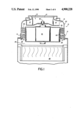
- FIG. 1 is a cross-section of a centrifugal blower and automobile air conditioner evaporator.
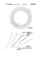
- FIG. 2A is a cross sectional representation of the impeller blades of the blower of FIG. 1.
- FIG. 2B is an enlarged detail of a portion of FIG. 2A.
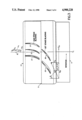
- FIG. 3 is a top view, partially broken away, of the annular envelope of the blower of FIG. 1.
- FIG. 4 is a graph of pressure as a function of tangential swirl velocity.
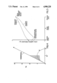
- FIG. 5 is a plot of local surface pressure as a function of blade chord position.
- blower 10 includes an impeller 12 consisting of a plurality of blades (14 and 15, shown in FIG. 2) which are described in greater detail below. Impeller 12 is driven by an electric motor 16 attached to impeller axle 18.
- Impeller 12 rotates within stator 20, which is a part of generally cylindrical housing 21 extending co-axially with impeller 12 and motor 16.
- Generally cylindrical motor housing 22 forms the inner diameter of annular envelope 24.
- the outer diameter of annular envelope 24 is established by housing 21.
- C L is the centerline (axis) of the motor, blower and impeller.
- the vanes extract tangential (rotational or swirl) velocity from air leaving the impeller, and they recapture that energy as static pressure.
- Evaporator 30 is attached to the outlet 28 of envelope 24. Swirl in the airflow reaching evaporator 30 is substantially eliminated and air pressure across the evaporator is increased. Specifically, the vanes 25 and 27 are important in part because about 1/4 to 1/2 of the flow energy produced by a rearwardly curved centrifugal blower is in the form of velocity; the airfoil vanes recapture a substantial (40-80%) percentage of this flow energy.
- FIG. 4 diagram pressure coefficient (Cp) as a function of tangential swirl velocity (V t )
- Cp is defined by the following equation:
- V airflow velocity leaving the impeller
- V tip is the impeller tip velocity
- Vt* is the tangential velocity of air leaving the impeller ⁇ V t .
- angle of airfoil vanes 25 and 27 will depend upon the blade configuration (discussed below) and the rotational velocity of the impeller (i.e., the range of rotational velocity within which the blower is designed to operate). It is desirable to match the leading edge of the airfoil to the direction of airflow encountering that leading edge, so that the angle of incidence is negligible. In general, air approaches envelope 24 at an angle of 20-30° from tangential in the regime described above.
- FIG. 3 Superimposed on FIG. 3 is a vector diagram for flow V 1 entering the stator, in which V tl is the tangential swirl velocity entering the stator, and V xl is the axial velocity of the airstream entering the stator.
- V to is the tangential velocity of the blower wheel (impeller).
- Angle ⁇ 1 is 20-30° and angle B 1 is 60-70°. Similar diagrams could be drawn for flow leaving stage 1 and entering stage 2, and for flow leaving stage 2.
- the angle ⁇ 2 between V t2 and V x2 would be 80-90° and angle ⁇ 2 is between 0° and 10°.
- the second stage is necessary because the boundary layer loading value for a single stage exceeds the maximum engineering value (0.6) associated with attached flow.
- the diffusion factor is defined as (1-V 2 /V 1 )+(V t1 -V t2 )/2 ⁇ V 1 , where V 1 and V 2 are respective airflow velocities entering and leaving the stage, V t1 and V t2 are respective tangential velocities entering and leaving the stage, and ⁇ is blade solidity (i.e., blade chord ⁇ blade spacing).
- FIGS. 2A and 2B are cross-sectional representations of the blades 14 and 15 of the invention, showing their "S" shape (i.e. their reverse camber).
- the blades are backwardly curved, and (given their relatively small size) develop large thrust or pressure, with good efficiency and low noise.
- FIGS. 2A and 2B shows the "S" shape of long chord blades 14 and shorter chord auxiliary blades
- the suction side boundary layer must overcome three significant retarding forces: acceleration associated with the inertial reference frame curvature of the blade surface, a pressure gradient caused by the pressure rise that occurs from the blade leading edge to its trailing edge, and friction that exists at the blade-air interface. It is as though the air were rolling up hill; the air in the boundary layer begins its journey with a certain kinetic energy budget, which is partially dissipated by friction and partially converted into potential energy. At the same time the air follows a curved path, and the momentum change associated with this curvature thickens the boundary layer.
- the blower design of the invention has a combination of high positive camber near the leading edge and apparent negative camber between midchord and the training edge.
- the blade pulls hard on the flow when the boundary layer attachment is energetic, and pulls gently when the boundary layer attachment is weak. Pulling hard on the flow early produces room for more primary blades; reducing the boundary layer forces proportionately since the net work done by the blower is distributed over all of the blades surface.
- the blade configuration of a centrifugal blower is selected using, among other things, knowledge of the following characteristics of blowers:
- the pressure capacity of a blower increases as the square of the blade tip's tangential velocity at its outside diameter. This velocity is the product of diameter times rotation velocity. Thus, the pressure required by the application largely determines blower speed and diameter.
- the pressure generated in the blading increases, in theory, to a maximum when the blade exit angle is 90 degrees, as shown in FIG. 4. However, the pressure observed experimentally reaches a maximum when the blade exit angle is still backward curved, at an angle of perhaps 50-60 degrees. Essentially, the geometry of the blades defines a diffusion passage which has its largest total diffusion when the blade exit angle is 90 degrees. Boundary layer physics prevents realizing this maximum diffusion.
- the velocity of the air discharged by the blower increases as the blade exit angle increases, and reaches a maximum at a blade exit angle well beyond 90 degrees.
- the energy invested increases as the square of velocity. In applications where static pressure is required, it can be extracted from a high velocity discharge flow by diffusion.
- the efficiency of the diffusion process is generally far higher in the blading of the blower than in any process which diffuses the discharge flow--as high as 90 percent for the blading process, versus about 50 percent for the discharge process. It follows that the most efficient blower generally is the one which accomplishes the most diffusion in the blading. However, the blower blade design described herein accomplishes the combination of high efficiency along with small diameter and lower rotational velocity (leading to lower noise).
- the blade entry angle is defined by the RPM, the inlet diameter and leading edge blade span, and the flow design point (ft 3 /min.).
- FIG. 5 is a plot of local surface pressure (Cp) versus the blade chord position (designated as a percentage of total chord from 0 at the leading edge to 1 at the trailing edge), where Cp is defined by the following equation, in which P s is the surface pressure and V tip is the tip velocity:
- the plot of FIG. 5 is base a computer model of performance of the primary blades alone.
- the lower plot represents local surface pressure on the suction surface
- the upper plot represents local surface pressure on the pressure surface.
- the overall work done is represented by the difference between the average pressure entering the blade (left axis, one-half way between the two plots) and the average pressure leaving the blade (right axis, convergence of the two plots).
- the plot in FIG. 5 represents a flow of 240 CFM, a static pressure of 2.29 and a static efficiency of 0.46.
- the "S" shaped blade of the invention pulls hard, as indicated in FIG. 5 by the ⁇ Cp from the high pressure side of the blade to the suction side of the blade, in the chord region 0.0-0.4. For the chord region 0.4-1.0, the blade does less work.
- the blades have a high positive camber near the leading edge and a negative camber at some point between the mid-point and the tail of the blade.
- the positive camber reaches a maximum of 1-3% in the leading half (e.g. 20-30%) of the blade, and the negative camber is 0.25%-3% in the trailing half (e.g. 70-80%) of the blade.
- the operating regime of the blower is further defined by the flow number (J) and the pressure number (K t ) as follows: ##EQU1##
- n rotational velocity in revolutions/second
- D diameter of the impeller in feet.
- Static pressure is measured in inches of water and is corrected to atmospheric pressure (29.92 inches Hg).
- the flow number J is between 0.35 and 0.8 and the pressure number K t >2.4.
- the blade chord Reynolds number is 40,000 to 200,000. Blowers with these characteristics are less than 2 feet in diameter and preferably less than 12 inches.
- the cross-sectional area of the outlet 28 of envelope 24 is larger (at least 1.2X) than the area of inlet area 13.
- the increased area represents blade diffusion, since outlet 28 is filled with airflow.
- the decreased inlet area significantly reduces noise.
- the blower is manufactured by injection molding plastic, using e.g. fiber-filled plastic.
Landscapes
- Engineering & Computer Science (AREA)
- Mechanical Engineering (AREA)
- General Engineering & Computer Science (AREA)
- Structures Of Non-Positive Displacement Pumps (AREA)
Abstract
Description
Cp=1/2ρV.sup.2 ÷1/2ρV.sup.2.sub.tip
Cp=P.sub.s ÷1/2p (V.sub.tip).sup.2
Claims (8)
Priority Applications (6)
| Application Number | Priority Date | Filing Date | Title |
|---|---|---|---|
| US07/310,664 US4900228A (en) | 1989-02-14 | 1989-02-14 | Centrifugal fan with variably cambered blades |
| ES90903507T ES2078335T3 (en) | 1989-02-14 | 1990-02-05 | A CENTRIFUGAL BLOWER AND PROPELLER. |
| EP90903507A EP0458864B1 (en) | 1989-02-14 | 1990-02-05 | Centrifugal fan with variably cambered blades |
| JP2503833A JPH04505201A (en) | 1989-02-14 | 1990-02-05 | centrifugal blower |
| DE69022405T DE69022405T2 (en) | 1989-02-14 | 1990-02-05 | CENTRIFUGAL BLOWERS WITH VARIABLE CURVES. |
| PCT/US1990/000660 WO1990009525A1 (en) | 1989-02-14 | 1990-02-05 | Centrifugal fan with variably cambered blades |
Applications Claiming Priority (1)
| Application Number | Priority Date | Filing Date | Title |
|---|---|---|---|
| US07/310,664 US4900228A (en) | 1989-02-14 | 1989-02-14 | Centrifugal fan with variably cambered blades |
Publications (1)
| Publication Number | Publication Date |
|---|---|
| US4900228A true US4900228A (en) | 1990-02-13 |
Family
ID=23203572
Family Applications (1)
| Application Number | Title | Priority Date | Filing Date |
|---|---|---|---|
| US07/310,664 Expired - Lifetime US4900228A (en) | 1989-02-14 | 1989-02-14 | Centrifugal fan with variably cambered blades |
Country Status (6)
| Country | Link |
|---|---|
| US (1) | US4900228A (en) |
| EP (1) | EP0458864B1 (en) |
| JP (1) | JPH04505201A (en) |
| DE (1) | DE69022405T2 (en) |
| ES (1) | ES2078335T3 (en) |
| WO (1) | WO1990009525A1 (en) |
Cited By (31)
| Publication number | Priority date | Publication date | Assignee | Title |
|---|---|---|---|---|
| WO1991015664A1 (en) * | 1990-03-30 | 1991-10-17 | Airflow Research And Manufacturing Corporation | Space-efficient centrifugal blower |
| WO1992015787A1 (en) * | 1991-03-08 | 1992-09-17 | Baker Hughes Incorporated | Pitot pump with improved rotor cover |
| WO1993019946A1 (en) * | 1992-04-02 | 1993-10-14 | Ford Motor Company Limited | An air conditioning/heating module |
| US5588803A (en) * | 1995-12-01 | 1996-12-31 | General Motors Corporation | Centrifugal impeller with simplified manufacture |
| US5605444A (en) * | 1995-12-26 | 1997-02-25 | Ingersoll-Dresser Pump Company | Pump impeller having separate offset inlet vanes |
| US5743710A (en) * | 1996-02-29 | 1998-04-28 | Bosch Automotive Motor Systems Corporation | Streamlined annular volute for centrifugal blower |
| US5832606A (en) * | 1996-09-17 | 1998-11-10 | Elliott Turbomachinery Co., Inc. | Method for preventing one-cell stall in bladed discs |
| US6139273A (en) * | 1998-04-22 | 2000-10-31 | Valeo Climate Control, Inc. | Radial flow fan |
| US6447251B1 (en) | 2000-04-21 | 2002-09-10 | Revcor, Inc. | Fan blade |
| WO2002070139A2 (en) * | 2001-03-05 | 2002-09-12 | Robert Bosch Corporation | Compact centrifugal blower with annular stator |
| US6461103B2 (en) * | 2000-05-16 | 2002-10-08 | Lg Electronics Inc. | Siroco fan of a window type air conditioner |
| US6488472B1 (en) * | 2000-01-28 | 2002-12-03 | Seiko Epson Corporation | Axial fan, centrifugal fan, and electronic equipment employing one of these fans |
| US20020197162A1 (en) * | 2000-04-21 | 2002-12-26 | Revcor, Inc. | Fan blade |
| US20030223875A1 (en) * | 2000-04-21 | 2003-12-04 | Hext Richard G. | Fan blade |
| US20040101407A1 (en) * | 2002-11-27 | 2004-05-27 | Pennington Donald R. | Fan assembly and method |
| US20040105757A1 (en) * | 2002-07-24 | 2004-06-03 | Michio Kitazume | Multiblade blower |
| US20050163614A1 (en) * | 2004-01-23 | 2005-07-28 | Robert Bosch Gmbh | Centrifugal blower |
| US20050260070A1 (en) * | 2004-05-19 | 2005-11-24 | Delta Electronics, Inc. | Heat-dissipating device |
| US20080292464A1 (en) * | 2004-07-31 | 2008-11-27 | Ebm-Papst Landshut Gmbh | Radial Fan Impeller |
| US20090136357A1 (en) * | 2007-11-27 | 2009-05-28 | Emerson Electric Co. | Bi-Directional Cooling Fan |
| US20090317237A1 (en) * | 2008-06-20 | 2009-12-24 | General Electric Company | System and method for reduction of unsteady pressures in turbomachinery |
| CN101922468A (en) * | 2010-03-24 | 2010-12-22 | 南通大通宝富风机有限公司 | Impeller of centrifugal fan |
| US20110027094A1 (en) * | 2009-07-31 | 2011-02-03 | Rem Enterprises Inc. | Blower for a particulate loader and transfer apparatus |
| US20110182748A1 (en) * | 2010-01-27 | 2011-07-28 | Kwok Lo Ching | Centrifugal impeller |
| US20130004329A1 (en) * | 2010-03-15 | 2013-01-03 | Yukishige Shiraichi | Fan, molding die, and fluid feeder |
| CN103225625A (en) * | 2013-03-28 | 2013-07-31 | 无锡小天鹅股份有限公司 | Centrifugal fan and clothes dryer with same |
| US20130236303A1 (en) * | 2012-03-12 | 2013-09-12 | Nidec Corporation | Centrifugal fan |
| US20150118037A1 (en) * | 2013-10-28 | 2015-04-30 | Minebea Co., Ltd. | Centrifugal fan |
| US20160146214A1 (en) * | 2014-11-20 | 2016-05-26 | Baker Hughes Incorporated | Nozzle-Shaped Slots in Impeller Vanes |
| EP3066345A4 (en) * | 2013-12-23 | 2017-07-26 | Fisher&Paykel Healthcare Limited | Blower for breathing apparatus |
| US10227993B2 (en) | 2014-10-30 | 2019-03-12 | Nidec Corporation | Blower apparatus and vacuum cleaner |
Families Citing this family (3)
| Publication number | Priority date | Publication date | Assignee | Title |
|---|---|---|---|---|
| WO2008109037A1 (en) * | 2007-03-05 | 2008-09-12 | Xcelaero Corporation | Low camber microfan |
| JP6411118B2 (en) * | 2014-07-31 | 2018-10-24 | 株式会社日立製作所 | Centrifugal impeller, single-shaft multistage centrifugal compressor using the same, and method of manufacturing centrifugal impeller |
| JP2019082129A (en) * | 2017-10-30 | 2019-05-30 | 株式会社デンソー | Blower |
Citations (18)
| Publication number | Priority date | Publication date | Assignee | Title |
|---|---|---|---|---|
| US13200A (en) * | 1855-07-03 | Cork-machine | ||
| US1240949A (en) * | 1914-08-03 | 1917-09-25 | Buffalo Forge Co | Centrifugal fan. |
| US2975962A (en) * | 1957-05-10 | 1961-03-21 | Konink Maschf Gebr Stork & Co | Impellers for centrifugal fans |
| US3597117A (en) * | 1969-01-10 | 1971-08-03 | Rotorn Inc | Fan for narrow environments |
| DE2210271A1 (en) * | 1972-03-03 | 1973-09-13 | Ltg Lufttechnische Gmbh | CENTRIFUGAL FAN |
| GB1426503A (en) * | 1972-06-05 | 1976-03-03 | Westinghouse Electric Corp | Heat exchanger unit |
| US3967874A (en) * | 1975-09-30 | 1976-07-06 | Calabro Anthony Denis | Uniformly cooled printed circuit board mounting assembly |
| GB1473919A (en) * | 1975-03-17 | 1977-05-18 | British Leyland Uk Ltd | Motor vehicle engine-cooling system |
| GB1483455A (en) * | 1973-09-08 | 1977-08-17 | Nu Way Heating Plants Ltd | Radial flow blowers |
| US4269571A (en) * | 1979-08-14 | 1981-05-26 | Kabushiki Kaisha Shikutani | Blowing apparatus |
| GB2063365A (en) * | 1979-10-08 | 1981-06-03 | Punker Gmbh | Radial Flow Fans |
| GB2080879A (en) * | 1980-07-28 | 1982-02-10 | Gebhardt Gmbh Wilhelm | Flow guides for centrifugal fans |
| CA1157902A (en) * | 1980-08-02 | 1983-11-29 | Rudolf Zinsser | Casing for a fan-forced heater having a radial blower |
| JPS5941700A (en) * | 1982-09-01 | 1984-03-07 | Matsushita Electric Ind Co Ltd | Electric blower |
| US4526506A (en) * | 1982-12-29 | 1985-07-02 | Wilhelm Gebhardt Gmbh | Radial fan with backwardly curving blades |
| JPS60125798A (en) * | 1983-12-09 | 1985-07-05 | Matsushita Electric Ind Co Ltd | Motor fan |
| US4531890A (en) * | 1983-01-24 | 1985-07-30 | Stokes Walter S | Centrifugal fan impeller |
| GB2166494A (en) * | 1984-10-31 | 1986-05-08 | Wolter Masch & Apparate | Fan |
Family Cites Families (7)
| Publication number | Priority date | Publication date | Assignee | Title |
|---|---|---|---|---|
| FR1170390A (en) * | 1956-03-31 | 1959-01-14 | Appbau Rothemuehle Dr Brandt & | rotating blade element for centrifugal machines |
| FR1162814A (en) * | 1956-04-12 | 1958-09-17 | Bronswerk Nv | Impeller for fan |
| FR1308014A (en) * | 1961-09-20 | 1962-11-03 | Centrifugal compressor | |
| CH616728A5 (en) * | 1975-07-31 | 1980-04-15 | Le Polt I Im M I Kalinina | Radial-flow compressor. |
| JPS55134797A (en) * | 1979-04-06 | 1980-10-20 | Hitachi Ltd | Centrifugal vane |
| JPS58128243A (en) * | 1982-01-27 | 1983-07-30 | Nippon Light Metal Co Ltd | Production of impeller |
| JPS6012798A (en) * | 1984-02-17 | 1985-01-23 | 株式会社日立製作所 | Device for supplying electronic part |
-
1989
- 1989-02-14 US US07/310,664 patent/US4900228A/en not_active Expired - Lifetime
-
1990
- 1990-02-05 DE DE69022405T patent/DE69022405T2/en not_active Expired - Lifetime
- 1990-02-05 EP EP90903507A patent/EP0458864B1/en not_active Expired - Lifetime
- 1990-02-05 JP JP2503833A patent/JPH04505201A/en active Pending
- 1990-02-05 ES ES90903507T patent/ES2078335T3/en not_active Expired - Lifetime
- 1990-02-05 WO PCT/US1990/000660 patent/WO1990009525A1/en active IP Right Grant
Patent Citations (18)
| Publication number | Priority date | Publication date | Assignee | Title |
|---|---|---|---|---|
| US13200A (en) * | 1855-07-03 | Cork-machine | ||
| US1240949A (en) * | 1914-08-03 | 1917-09-25 | Buffalo Forge Co | Centrifugal fan. |
| US2975962A (en) * | 1957-05-10 | 1961-03-21 | Konink Maschf Gebr Stork & Co | Impellers for centrifugal fans |
| US3597117A (en) * | 1969-01-10 | 1971-08-03 | Rotorn Inc | Fan for narrow environments |
| DE2210271A1 (en) * | 1972-03-03 | 1973-09-13 | Ltg Lufttechnische Gmbh | CENTRIFUGAL FAN |
| GB1426503A (en) * | 1972-06-05 | 1976-03-03 | Westinghouse Electric Corp | Heat exchanger unit |
| GB1483455A (en) * | 1973-09-08 | 1977-08-17 | Nu Way Heating Plants Ltd | Radial flow blowers |
| GB1473919A (en) * | 1975-03-17 | 1977-05-18 | British Leyland Uk Ltd | Motor vehicle engine-cooling system |
| US3967874A (en) * | 1975-09-30 | 1976-07-06 | Calabro Anthony Denis | Uniformly cooled printed circuit board mounting assembly |
| US4269571A (en) * | 1979-08-14 | 1981-05-26 | Kabushiki Kaisha Shikutani | Blowing apparatus |
| GB2063365A (en) * | 1979-10-08 | 1981-06-03 | Punker Gmbh | Radial Flow Fans |
| GB2080879A (en) * | 1980-07-28 | 1982-02-10 | Gebhardt Gmbh Wilhelm | Flow guides for centrifugal fans |
| CA1157902A (en) * | 1980-08-02 | 1983-11-29 | Rudolf Zinsser | Casing for a fan-forced heater having a radial blower |
| JPS5941700A (en) * | 1982-09-01 | 1984-03-07 | Matsushita Electric Ind Co Ltd | Electric blower |
| US4526506A (en) * | 1982-12-29 | 1985-07-02 | Wilhelm Gebhardt Gmbh | Radial fan with backwardly curving blades |
| US4531890A (en) * | 1983-01-24 | 1985-07-30 | Stokes Walter S | Centrifugal fan impeller |
| JPS60125798A (en) * | 1983-12-09 | 1985-07-05 | Matsushita Electric Ind Co Ltd | Motor fan |
| GB2166494A (en) * | 1984-10-31 | 1986-05-08 | Wolter Masch & Apparate | Fan |
Non-Patent Citations (1)
| Title |
|---|
| European Patent 72,177, Feb. 1983. * |
Cited By (54)
| Publication number | Priority date | Publication date | Assignee | Title |
|---|---|---|---|---|
| WO1991015664A1 (en) * | 1990-03-30 | 1991-10-17 | Airflow Research And Manufacturing Corporation | Space-efficient centrifugal blower |
| WO1992015787A1 (en) * | 1991-03-08 | 1992-09-17 | Baker Hughes Incorporated | Pitot pump with improved rotor cover |
| WO1993019946A1 (en) * | 1992-04-02 | 1993-10-14 | Ford Motor Company Limited | An air conditioning/heating module |
| US5335718A (en) * | 1992-04-02 | 1994-08-09 | Ford Motor Company | Space-efficient air conditioning/heating module |
| US5588803A (en) * | 1995-12-01 | 1996-12-31 | General Motors Corporation | Centrifugal impeller with simplified manufacture |
| US5605444A (en) * | 1995-12-26 | 1997-02-25 | Ingersoll-Dresser Pump Company | Pump impeller having separate offset inlet vanes |
| US5743710A (en) * | 1996-02-29 | 1998-04-28 | Bosch Automotive Motor Systems Corporation | Streamlined annular volute for centrifugal blower |
| US5832606A (en) * | 1996-09-17 | 1998-11-10 | Elliott Turbomachinery Co., Inc. | Method for preventing one-cell stall in bladed discs |
| US6139273A (en) * | 1998-04-22 | 2000-10-31 | Valeo Climate Control, Inc. | Radial flow fan |
| US6488472B1 (en) * | 2000-01-28 | 2002-12-03 | Seiko Epson Corporation | Axial fan, centrifugal fan, and electronic equipment employing one of these fans |
| US6447251B1 (en) | 2000-04-21 | 2002-09-10 | Revcor, Inc. | Fan blade |
| US6814545B2 (en) | 2000-04-21 | 2004-11-09 | Revcor, Inc. | Fan blade |
| US20020197162A1 (en) * | 2000-04-21 | 2002-12-26 | Revcor, Inc. | Fan blade |
| US20030223875A1 (en) * | 2000-04-21 | 2003-12-04 | Hext Richard G. | Fan blade |
| US20050123404A1 (en) * | 2000-04-21 | 2005-06-09 | Revcor, Inc. | Fan blade |
| US6712584B2 (en) | 2000-04-21 | 2004-03-30 | Revcor, Inc. | Fan blade |
| US6461103B2 (en) * | 2000-05-16 | 2002-10-08 | Lg Electronics Inc. | Siroco fan of a window type air conditioner |
| WO2002070139A2 (en) * | 2001-03-05 | 2002-09-12 | Robert Bosch Corporation | Compact centrifugal blower with annular stator |
| WO2002070139A3 (en) * | 2001-03-05 | 2004-03-18 | Bosch Robert Corp | Compact centrifugal blower with annular stator |
| US6685430B2 (en) | 2001-03-05 | 2004-02-03 | Robert Bosch Corporation | Compact centrifugal blower with annular stator |
| CN1330880C (en) * | 2002-07-24 | 2007-08-08 | 三电有限公司 | Multiple vanes for blower |
| US6984111B2 (en) * | 2002-07-24 | 2006-01-10 | Sanden Corporation | Multiblade blower |
| US20040105757A1 (en) * | 2002-07-24 | 2004-06-03 | Michio Kitazume | Multiblade blower |
| US6942457B2 (en) | 2002-11-27 | 2005-09-13 | Revcor, Inc. | Fan assembly and method |
| US20040101407A1 (en) * | 2002-11-27 | 2004-05-27 | Pennington Donald R. | Fan assembly and method |
| US20050163614A1 (en) * | 2004-01-23 | 2005-07-28 | Robert Bosch Gmbh | Centrifugal blower |
| US7108482B2 (en) | 2004-01-23 | 2006-09-19 | Robert Bosch Gmbh | Centrifugal blower |
| US20050260070A1 (en) * | 2004-05-19 | 2005-11-24 | Delta Electronics, Inc. | Heat-dissipating device |
| US7607886B2 (en) * | 2004-05-19 | 2009-10-27 | Delta Electronics, Inc. | Heat-dissipating device |
| US7794206B2 (en) * | 2004-07-31 | 2010-09-14 | Emb-Papst Landshut Gmbh | Radial fan impeller |
| US20080292464A1 (en) * | 2004-07-31 | 2008-11-27 | Ebm-Papst Landshut Gmbh | Radial Fan Impeller |
| US20090136357A1 (en) * | 2007-11-27 | 2009-05-28 | Emerson Electric Co. | Bi-Directional Cooling Fan |
| US8007241B2 (en) * | 2007-11-27 | 2011-08-30 | Nidec Motor Corporation | Bi-directional cooling fan |
| US20090317237A1 (en) * | 2008-06-20 | 2009-12-24 | General Electric Company | System and method for reduction of unsteady pressures in turbomachinery |
| US20110027094A1 (en) * | 2009-07-31 | 2011-02-03 | Rem Enterprises Inc. | Blower for a particulate loader and transfer apparatus |
| US8764400B2 (en) * | 2009-07-31 | 2014-07-01 | Ag Growth Industries Partnership | Blower for a particulate loader and transfer apparatus |
| US8882467B2 (en) * | 2010-01-27 | 2014-11-11 | Johnson Electric S.A. | Centrifugal impeller |
| US20110182748A1 (en) * | 2010-01-27 | 2011-07-28 | Kwok Lo Ching | Centrifugal impeller |
| US20130004329A1 (en) * | 2010-03-15 | 2013-01-03 | Yukishige Shiraichi | Fan, molding die, and fluid feeder |
| EP2549117A4 (en) * | 2010-03-15 | 2017-10-04 | Sharp Kabushiki Kaisha | Fan, metallic mold, and fluid delivery device |
| US9206815B2 (en) * | 2010-03-15 | 2015-12-08 | Sharp Kabushiki Kaisha | Fan, molding die, and fluid feeder |
| US9885364B2 (en) | 2010-03-15 | 2018-02-06 | Sharp Kabushiki Kaisha | Fan, molding die, and fluid feeder |
| US9869324B2 (en) | 2010-03-15 | 2018-01-16 | Sharp Kabushiki Kaisha | Fan, molding die, and fluid feeder |
| CN101922468A (en) * | 2010-03-24 | 2010-12-22 | 南通大通宝富风机有限公司 | Impeller of centrifugal fan |
| US20130236303A1 (en) * | 2012-03-12 | 2013-09-12 | Nidec Corporation | Centrifugal fan |
| US10662969B2 (en) * | 2012-03-12 | 2020-05-26 | Nidec Corporation | Centrifugal fan |
| US9574565B2 (en) * | 2012-03-12 | 2017-02-21 | Nidec Corporation | Centrifugal fan having main blade with axially upper end projecting upward |
| US20170159662A1 (en) * | 2012-03-12 | 2017-06-08 | Nidec Corporation | Centrifugal fan |
| CN103225625A (en) * | 2013-03-28 | 2013-07-31 | 无锡小天鹅股份有限公司 | Centrifugal fan and clothes dryer with same |
| US20150118037A1 (en) * | 2013-10-28 | 2015-04-30 | Minebea Co., Ltd. | Centrifugal fan |
| EP3066345A4 (en) * | 2013-12-23 | 2017-07-26 | Fisher&Paykel Healthcare Limited | Blower for breathing apparatus |
| US10227993B2 (en) | 2014-10-30 | 2019-03-12 | Nidec Corporation | Blower apparatus and vacuum cleaner |
| US9777741B2 (en) * | 2014-11-20 | 2017-10-03 | Baker Hughes Incorporated | Nozzle-shaped slots in impeller vanes |
| US20160146214A1 (en) * | 2014-11-20 | 2016-05-26 | Baker Hughes Incorporated | Nozzle-Shaped Slots in Impeller Vanes |
Also Published As
| Publication number | Publication date |
|---|---|
| ES2078335T3 (en) | 1995-12-16 |
| DE69022405T2 (en) | 1996-03-07 |
| JPH04505201A (en) | 1992-09-10 |
| EP0458864B1 (en) | 1995-09-13 |
| EP0458864A1 (en) | 1991-12-04 |
| WO1990009525A1 (en) | 1990-08-23 |
| DE69022405D1 (en) | 1995-10-19 |
| EP0458864A4 (en) | 1991-12-11 |
Similar Documents
| Publication | Publication Date | Title |
|---|---|---|
| US4900228A (en) | Centrifugal fan with variably cambered blades | |
| US4946348A (en) | Centrifugal fan with airfoil vanes in annular volute envelope | |
| KR100827055B1 (en) | Double bowed compressor airfoil | |
| US3788765A (en) | Low specific speed compressor | |
| JP3528285B2 (en) | Axial blower | |
| CN100508332C (en) | Cooling device of motor | |
| US20100189557A1 (en) | Impeller and fan | |
| JPS5990797A (en) | Centrifugal compressor and compression method | |
| WO2008109036A1 (en) | High efficiency cooling fan | |
| JP2007529662A (en) | Turbine and rotor therefor | |
| US7186080B2 (en) | Fan inlet and housing for a centrifugal blower whose impeller has forward curved fan blades | |
| CN109667790A (en) | A kind of bionical leading edge blade of INVESTIGATION ON A HIGH SPEED CENTRIFUGAL COMPRESSOR | |
| EP1210264A1 (en) | Centrifugal impeller with high blade camber | |
| JP2002106494A (en) | Axial flow type fan | |
| WO1990009526A1 (en) | Centrifugal fan with airfoil vanes in annular volute envelope | |
| JPS59173598A (en) | Axial fan | |
| JP2573292B2 (en) | High speed centrifugal compressor | |
| WO2014072692A2 (en) | Continuous band propeller | |
| JPS5893997A (en) | Blower | |
| JPH0474560B2 (en) | ||
| CN220505393U (en) | Axial flow wind wheel, air conditioner external unit and air conditioner | |
| CN2711425Y (en) | High-efficient low-noise centrifugal blower fan | |
| KR100852950B1 (en) | Blade Structure of Axial Flow Fan | |
| JP3123328B2 (en) | Blower impeller | |
| CN209892508U (en) | Axial flow fan blade and electric fan |
Legal Events
| Date | Code | Title | Description |
|---|---|---|---|
| AS | Assignment |
Owner name: AIRFLOW RESEARCH AND MANUFACTURING CORPORATION, A Free format text: ASSIGNMENT OF ASSIGNORS INTEREST.;ASSIGNOR:YAPP, MARTIN G.;REEL/FRAME:005042/0773 Effective date: 19890210 |
|
| STCF | Information on status: patent grant |
Free format text: PATENTED CASE |
|
| CC | Certificate of correction | ||
| FPAY | Fee payment |
Year of fee payment: 4 |
|
| FEPP | Fee payment procedure |
Free format text: PAT HLDR NO LONGER CLAIMS SMALL ENT STAT AS SMALL BUSINESS (ORIGINAL EVENT CODE: LSM2); ENTITY STATUS OF PATENT OWNER: LARGE ENTITY |
|
| REFU | Refund |
Free format text: REFUND OF EXCESS PAYMENTS PROCESSED (ORIGINAL EVENT CODE: R169); ENTITY STATUS OF PATENT OWNER: LARGE ENTITY |
|
| AS | Assignment |
Owner name: BG AUTOMOTIVE MOTORS, INC., TENNESSEE Free format text: MERGER;ASSIGNOR:AIRFLOW RESEARCH AND MANUFACTURING CORPORATION;REEL/FRAME:007648/0175 Effective date: 19950103 Owner name: BOSCH AUTOMOTIVE MOTOR SYSTEMS CORPORATION, TENNES Free format text: CHANGE OF NAME;ASSIGNOR:BG AUTOMOTIVE MOTORS, INC.;REEL/FRAME:007596/0416 Effective date: 19950202 |
|
| FPAY | Fee payment |
Year of fee payment: 8 |
|
| FPAY | Fee payment |
Year of fee payment: 12 |
|
| REMI | Maintenance fee reminder mailed | ||
| FEPP | Fee payment procedure |
Free format text: PAYOR NUMBER ASSIGNED (ORIGINAL EVENT CODE: ASPN); ENTITY STATUS OF PATENT OWNER: LARGE ENTITY |