US4900231A - Auxiliary compressor air supply for an aircraft - Google Patents
Auxiliary compressor air supply for an aircraft Download PDFInfo
- Publication number
- US4900231A US4900231A US06/869,391 US86939186A US4900231A US 4900231 A US4900231 A US 4900231A US 86939186 A US86939186 A US 86939186A US 4900231 A US4900231 A US 4900231A
- Authority
- US
- United States
- Prior art keywords
- input
- compressor
- electric motor
- engine
- aircraft
- Prior art date
- Legal status (The legal status is an assumption and is not a legal conclusion. Google has not performed a legal analysis and makes no representation as to the accuracy of the status listed.)
- Expired - Fee Related
Links
Images
Classifications
-
- B—PERFORMING OPERATIONS; TRANSPORTING
- B64—AIRCRAFT; AVIATION; COSMONAUTICS
- B64D—EQUIPMENT FOR FITTING IN OR TO AIRCRAFT; FLIGHT SUITS; PARACHUTES; ARRANGEMENTS OR MOUNTING OF POWER PLANTS OR PROPULSION TRANSMISSIONS IN AIRCRAFT
- B64D41/00—Power installations for auxiliary purposes
Definitions
- This invention relates to the generation of compressed air for use in providing pneumatic services aboard an aircraft. More specifically, it relates to the provision of an auxiliary compressor for generating the pneumatic services air supply which is driven by engine shaft power along during relatively high power operation of the engine, and by both engine shaft power and an electric motor during periods of low power operation of the engine.
- the operation of an aircraft requires the provision of a source of compressed air for pressurizing the cabin of the aircraft and providing other pneumatic services aboard the aircraft.
- the compressed air used for the pneumatic services has been obtained in different ways.
- One way is to design the engines of the aircraft in such a way that air can be bleed off from the compressors of the engines and used for the pneumatic services.
- Known direct drive systems utilize an auxiliary shaft which is connected at one end to the engine shaft and at its opposite end to the auxiliary compressor.
- Known indirect systems utilize a hydraulic pump which is driven by the engine shaft and which in turn drives a hydraulic motor which is connected to the auxiliary compressor.
- Known systems for producing pneumatic services air aboard aircraft have required compromises in operating efficiencies of the engines over a wide band of operating requirements.
- the known systems which comprise auxiliary air compressors coupled to the engine either require gear shifting transmissions, or are designed to handle worst case design conditions and operate in surge relief during some of the normal operating conditions.
- Known systems which comprise remotely powered compressors, driven either by hydraulic motors powered by the hydraulic system aboard the aircraft or electric motors powered by the electric system aboard the aircraft take substantial amonts of power from the aircraft hydraulic or electrical systems, and are generally also chacterized by costly line losses of power.
- the system of the present invention applies recent technological advances in electric motors with the best features of known auxiliary compressor sytems, to produce a maximum efficiency system which does not require the mechanical complexity of gear shifting and/or slip couplings, and which does not experience substantial amounts of power waste.
- an auxiliary compressor for generating pneumatic service air.
- the output of a differential gearing is drivenly connected to the compressor rotor.
- Engine shaft power provides a first input to the differential gearing.
- An electric motor provides a second input for the differential gearing.
- engine shaft power alone is used for driving the air compressor.
- a droop in air compressor output is sensed, and this sensed condition is used as a basis for controlling the electric motor, in a manner such that the drive input of the electric motor combined with the drive input of the engine shaft will produce a desired output from the air compressor.
- the electric motor is a variable speed electric motor, of a type producing an output torque that is substantially linearly proportional to the input current to the motor.
- the electric motor is a brushless permanent magnet type motor characterized by a relatively large torque output and a relatively small size.
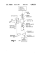
- FIG. 1 of the drawing is a schematic diagram of an embodiment of the present invention, such diagram including both legends and reference numerals;
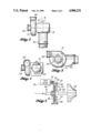
- FIG. 2 is a top plan view of an example package design of a compressor, a differential gear box and a speed trim motor;
- FIG. 3 is an elevational view of the package shown by FIG. 2, looking toward the inlet of the compressor;
- FIG. 4 is an end elevational view of the package shown by FIGS. 2 and 3, looking towards an end of the speed trim motor;
- FIG. 5 is a schematic view of a differential gear box and its connection between the main engine shaft, the speed trim motor and the compressor rotor.
- an aircraft propulsion engine 10 is shown by a block diagram.
- This engine 10 is a gas turbine engine. It comprises a compressor section, a combustion chamber section and a turbine section, in series.
- an auxiliary compressor 12 i.e. a compressor separate from the engine 10, is provided for generating the compressed air that is used for cabin pressurization, air conditioning, etc.
- this compressed air will be sometimes referred to as the "pneumatic services air.”
- engine shaft power is used for driving the compressor 12 during relatively high power operation of the engine 10, e.g. during climb and cruise operation.
- a power take-off shaft 14 is provided which at one end is suitably connected to the turbine shaft of the engine 10, e.g. by meshing bevel gears.
- the shaft 14 provides a first input 16 into a differential gear box 18.
- Shaft 14 may include a one-way drive coupling 20.
- the differential gear box 18 has an output shaft 22 which is connected to the rotor 24 of the compressor 12.
- Compressor 12 includes an air inlet 26 and an air outlet 28.
- the outlet 28 is connected to deliver the effluent of the compressor 12 to the various pneumatic services, e.g. to the aircraft cabin for pressurization.
- the pneumatic services system will include various controls and conditioning components which are not a part of this invention.
- the differential gear box 18 includes a second input 30.
- This input 30 includes a shaft which is driven by an electric motor 32, herein termed "the speed trim drive motor.”
- the output shaft of motor 32 may include a one-way drive coupling 34.
- the electric motor 32 is an electronically commutated brushless electric motor.
- This type of motor is a known but relatively new development and it is the availability of this motor which has made the present invention feasible and advantageous.
- This type of motor owes its basic simplicity and absolute minimum of moving parts to a permanent magnet field assembly (e.g. Samarium cobalt magnets).
- the motor 12 is characterized by high linearity.
- the torque increases directly with input current, independent of speed or angular position.
- the motor can be constructed in many different configurations, each of which involves a small envelope, enabling the motor 32 to be fitted into a quite small space.
- a motor of this type capable of generating about 102 hp, can fit within an envelope measuring about 12 inches long by about 8 inches in diameter.
- the aircraft may include a starter generator 38 that is first used for intiating start rotation of the engine 10. Then, when engine 10 is operating, the starter/generator 38 will be coupled to the engine 10, to be driven thereby, and controlled to function as a generator.
- the present invention does not rely on the presence of this particular type of electrical power supply. Rather, the electrical power supply 36 may take any suitable form. It is only necessary that the aircraft include an electrical power supply 36 of some form.
- a device or sensor is associated with the compressor 12, to measure the output of the compressor 12.
- This device may be in the form of a shaft speed sensor 40 which measures the rotational speed of the output shaft 22 from the gear box 18. This also constitutes a measurement of the rotational speed of the compressor rotor 24.
- the sensor 40 produces a signal which is transmitted to a compressor speed controller 42.
- the compressor speed controller 42 may be in the form of a microprocessor which takes the signal from sensor 40 and compares it with model information. During periods of reduced power operation of the aircraft, e.g. descent with idle engine power, a droop in compressor speed is detected by the sensor 40. In response, the compressor speed controller 42 functions to operate a frequency converter 44 which is interconnected between the electrical power supply 36 and the speed trim drive motor 32.
- the compressor speed controller 42 and the frequency converter 44 function to operate the speed trim drive motor 32 in a manner resulting in its input to the differential gear box 18, combined with the decreased power input from the engine shaft 14, providing a constant output rotation of the gear box shaft 22.
- This selected operation of the compressor 12 may be provided by other command information that is processed in the compressor speed controller 42.
- the sensor 40 for detecting speed of rotation compressor rotor shaft, the compressor speed controller or microprocessor 42 and the frequency converter 44 are all elements which are known per se and are commercially available. Accordingly, these common elements of the system are merely shown in a schematic or block diagrm form.
- the one-way drive coupling 20, 34 may be one-way overriding clutches of the type shown in U.S. Pat. No. 2,723,531 (elements 17, 24, 32, 34), granted Nov. 15, 1955, to Leond R. Wosika et al.
- the one-way drive coupling 20 in shaft 16 functions to prevent the second input 30 into the differential gear box 18 from back driving the shaft 14.
- the one-way drive coupling 34 between motor 32 and gear box input 30 prevents a first input 16 from back driving the motor 32.
- the differential gear box 18 is per se not a part of the present invention; it involves known technology. Accordingly the differential gear box 18 is also shown in block diagram form in FIG. 1.
- the differential gear box 18 functions to produce an output shaft speed which is additive of the two input shaft speeds, or which is at least a function of the sum of the two inputs 16, 30.
- FIG. 5 sets forth the drive system in schematic form, minus right angle gearing, etc.
- the shaft 16 which is connected to the drive shaft of the main engine is shown connected to a rotary carrier 46.
- the carrier 46 carries a plurality of planet gears 48, each suitably mounted to rotate about an axis 50.
- the gears 48 mesh with a sun gear 52 and a ring gear 54.
- the sun gear 52 is connected to the compressor shaft 22.
- Ring gear 54 is a part of a rotating member 56 which includes a second ring gear section 58.
- the output shaft 30 of the speed trim drive motor 32 is connected to an output gear 60 which meshes with ring gear 58. Rotation of shaft 16 produces a rotation of the carrier 56 and the planet gears 48 carried thereby.
- Carrier movement of the gears 48 results in the gears 48 orbiting about the axis of ring gear 54 while at the same time rotating about their individual axes 50.
- the gearing is designed so that when the trim motor 32 is operating it drives the member 56 in a direction causing it to impart a driving force on the gears 48 which is additive to the driving force from the shaft 16 and the carrier 46. This enables operation of the trim motor 32 in such a manner that the trim motor can be used for maintaining the drive speed of the shaft 22 and the rotor 40, during low power operation of the main engine.
- FIGS. 2-4 disclose an advantages package design of the auxiliary compressor 12, the differential gear box 15 and the speed trim drive motor 32. This package is relatively small and can fit within space available adjacent the aircraft engine.
- FIG. 2 has been termed a top plan view
- FIG. 3 has been termed a side elevational view
- FIG. 4 has been termed an end elevational view. This was done for the purpose of describing the orientation of the views shown by FIGS. 2-4. These views are orthographic projections.
- the shaft 16 may extend away from the main engine shaft in any one of a large number of positions.
- the plan view, side elevational view and end elevational view terminology was done merely to relate the views to each other. They do not denote the actual positioning of the package in the aircraft. This positioning may vary substantially.
- the shaft 16 is shown to be coaxially related to the output shaft of the speed trim drive motor 32.
- the compressor rotor shaft 22 is shown to extend at a right angle to the shafts 16, 30. It is well within the skill of a person having ordinary skill in the art, to design a differential gear box transmission which will operate like the transmission shown schematically by FIG. 5, but which has the input to output orientation of the axes that is shown by FIGS. 2-4. In view of this fact, and in view of the fact that the invention does not depend upon the package design shown by FIG. 2-4 (i.e. the package design may vary from that shown), the details of construction of a suitable differential gear box is not considered to be a part of the present invention.
- the present invention is a system invention in which the differential gear box can exist in more than one form.
- the present invention makes it possible to operate advanced technology engines in an efficient manner because it is not necessary to design these engines so that they will have to supply substantial amounts of bleed air.
- the engines can be efficiently operated during climb and cruise maneuvers and sufficient shaft power will be available to by itself drive the compressor 12.
- the differential gear box 18 and the speed trim drive motor 32 are relatively small in size, and are relatively light weight in comparison to the advantages obtained by their use when the need arises.
- the speed trim drive motor 32 provides a second input 30 to the differential gear box 18, which is additive to the first input 16, to produce a desired output 22 for driving the compressor rotor 24.
- ground electrical power may constitute the electrical power supply 36. This would make it possible to use the compressor 12 to generate air conditioning air while the aircraft is on the ground and the engines 10 are not operating.
Abstract
Description
Claims (11)
Priority Applications (3)
| Application Number | Priority Date | Filing Date | Title |
|---|---|---|---|
| US06/869,391 US4900231A (en) | 1986-05-30 | 1986-05-30 | Auxiliary compressor air supply for an aircraft |
| EP87200274A EP0247641B1 (en) | 1986-05-30 | 1987-02-19 | Auxiliary compressor air supply for an aircraft |
| DE8787200274T DE3775465D1 (en) | 1986-05-30 | 1987-02-19 | AUXILIARY COMPRESSOR FOR THE AIR SUPPLY OF AN AIRCRAFT. |
Applications Claiming Priority (1)
| Application Number | Priority Date | Filing Date | Title |
|---|---|---|---|
| US06/869,391 US4900231A (en) | 1986-05-30 | 1986-05-30 | Auxiliary compressor air supply for an aircraft |
Publications (1)
| Publication Number | Publication Date |
|---|---|
| US4900231A true US4900231A (en) | 1990-02-13 |
Family
ID=25353465
Family Applications (1)
| Application Number | Title | Priority Date | Filing Date |
|---|---|---|---|
| US06/869,391 Expired - Fee Related US4900231A (en) | 1986-05-30 | 1986-05-30 | Auxiliary compressor air supply for an aircraft |
Country Status (3)
| Country | Link |
|---|---|
| US (1) | US4900231A (en) |
| EP (1) | EP0247641B1 (en) |
| DE (1) | DE3775465D1 (en) |
Cited By (35)
| Publication number | Priority date | Publication date | Assignee | Title |
|---|---|---|---|---|
| US5363032A (en) * | 1993-05-12 | 1994-11-08 | Sundstrand Corporation | Sensorless start of synchronous machine |
| US5384527A (en) * | 1993-05-12 | 1995-01-24 | Sundstrand Corporation | Rotor position detector with back EMF voltage estimation |
| US5428275A (en) * | 1993-05-12 | 1995-06-27 | Sundstrand Corporation | Controlled starting method for a gas turbine engine |
| US5430362A (en) * | 1993-05-12 | 1995-07-04 | Sundstrand Corporation | Engine starting system utilizing multiple controlled acceleration rates |
| US5444349A (en) * | 1993-05-12 | 1995-08-22 | Sundstrand Corporation | Starting control for an electromagnetic machine |
| US5461293A (en) * | 1993-05-12 | 1995-10-24 | Sundstrand Corporation | Rotor position detector |
| US5488286A (en) * | 1993-05-12 | 1996-01-30 | Sundstrand Corporation | Method and apparatus for starting a synchronous machine |
| US5493200A (en) * | 1993-05-12 | 1996-02-20 | Sundstrand Corporation | Control for a brushless generator |
| US5495162A (en) * | 1993-05-12 | 1996-02-27 | Sundstrand Corporation | Position-and-velocity sensorless control for starter generator electrical system using generator back-EMF voltage |
| US5495163A (en) * | 1993-05-12 | 1996-02-27 | Sundstrand Corporation | Control for a brushless generator operable in generating and starting modes |
| US5581168A (en) * | 1993-05-12 | 1996-12-03 | Sundstrand Corporation | Starter/generator system with DC link current control |
| US5594322A (en) * | 1993-05-12 | 1997-01-14 | Sundstrand Corporation | Starter/generator system with variable-frequency exciter control |
| US5606233A (en) * | 1994-08-08 | 1997-02-25 | Davis; James W. | System for generating electricity in a vehicle |
| US6142418A (en) * | 1998-05-12 | 2000-11-07 | Hamilton Sundstrand Corporation | Multi-path secondary power system for an aircraft |
| US6457306B1 (en) * | 1998-06-15 | 2002-10-01 | Lockheed Martin Corporation | Electrical drive system for rocket engine propellant pumps |
| US6638027B2 (en) | 2001-12-11 | 2003-10-28 | Visteon Global Technologies, Inc. | Hybrid compressor with bearing clutch assembly |
| US20070101721A1 (en) * | 2005-11-09 | 2007-05-10 | Pratt & Whitney Canada Corp. | Method and system for taxiing an aircraft |
| US20100034677A1 (en) * | 2008-08-05 | 2010-02-11 | Lennox Manufacturing Inc. | Dual-powered airflow generator |
| US8519555B2 (en) | 2010-11-29 | 2013-08-27 | Pratt & Whitney Canada Corp. | Combination low spool generator and ram air turbine generator |
| US20160172935A1 (en) * | 2014-12-15 | 2016-06-16 | Rolls-Royce Plc | Variable speed drive arrangement |
| US20170211891A1 (en) * | 2016-01-26 | 2017-07-27 | Ingersoll-Rand Company | Compressor having waste heat recovery with gas recycler |
| US20170222592A1 (en) * | 2016-02-01 | 2017-08-03 | Hamilton Sundstrand Corporation | Reducing Fault Energy from an Electric Motor Drive for a Compressor |
| US20170298822A1 (en) * | 2015-12-16 | 2017-10-19 | Airbus Operations, S.L. | Gas turbine engine for an aircraft |
| US10161271B2 (en) * | 2016-01-26 | 2018-12-25 | Ingersoll-Rand Company | Air compressor having supplemental power source |
| US20200141326A1 (en) * | 2018-11-02 | 2020-05-07 | Pratt & Whitney Canada Corp. | Gas turbine engine with differential gearbox |
| US11084591B2 (en) * | 2018-01-26 | 2021-08-10 | Rolls-Royce Plc | Aircraft cabin blower system having a transmission receiving mechanical power from a first and seccond input wherein the first input is configured to receive mechanical power from a turbine engine and a first electrical machine to configured to receive mechanical power from the turbine engine independent of the transmission |
| EP3912912A1 (en) * | 2020-05-21 | 2021-11-24 | Rolls-Royce plc | Aircraft cabin blower system |
| US11230385B2 (en) | 2017-06-08 | 2022-01-25 | General Electric Company | Hybrid-electric propulsion system for an aircraft |
| US11274599B2 (en) | 2019-03-27 | 2022-03-15 | Pratt & Whitney Canada Corp. | Air system switching system to allow aero-engines to operate in standby mode |
| US11274611B2 (en) | 2019-05-31 | 2022-03-15 | Pratt & Whitney Canada Corp. | Control logic for gas turbine engine fuel economy |
| US11326525B2 (en) | 2019-10-11 | 2022-05-10 | Pratt & Whitney Canada Corp. | Aircraft bleed air systems and methods |
| US11391219B2 (en) | 2019-04-18 | 2022-07-19 | Pratt & Whitney Canada Corp. | Health monitor for air switching system |
| US11608797B2 (en) | 2021-06-23 | 2023-03-21 | Raytheon Technologies Corporation | Hybrid electric engine including auxiliary compressor |
| US20230193776A1 (en) * | 2021-12-17 | 2023-06-22 | Rolls-Royce Plc | Pumping system |
| US11859563B2 (en) | 2019-05-31 | 2024-01-02 | Pratt & Whitney Canada Corp. | Air system of multi-engine aircraft |
Families Citing this family (1)
| Publication number | Priority date | Publication date | Assignee | Title |
|---|---|---|---|---|
| DE102007044229A1 (en) * | 2007-09-17 | 2009-03-19 | Airbus Deutschland Gmbh | Aircraft, engine arrangement and engine carrier |
Citations (17)
| Publication number | Priority date | Publication date | Assignee | Title |
|---|---|---|---|---|
| US1036328A (en) * | 1912-04-25 | 1912-08-20 | William T Pierce | Auxiliary power for pumping. |
| US2104387A (en) * | 1935-01-31 | 1938-01-04 | Gen Motors Corp | Refrigerating apparatus |
| US2104381A (en) * | 1935-01-31 | 1938-01-04 | Gen Motors Corp | Refrigerating apparatus |
| US2150276A (en) * | 1937-01-12 | 1939-03-14 | E L Kennedy | Refrigerating unit |
| US2271415A (en) * | 1937-12-02 | 1942-01-27 | Chrysler Corp | Refrigerating means for vehicles |
| US2374239A (en) * | 1941-03-29 | 1945-04-24 | Sedille Marcel Henri Louis | Gas turbine installation |
| US2405670A (en) * | 1942-08-17 | 1946-08-13 | Lockheed Aircraft Corp | Pressurizing equipment for aircraft |
| US2538299A (en) * | 1947-10-11 | 1951-01-16 | Servo Frein Dewandre | Motor pump and fan set for automobile vehicles |
| US2621476A (en) * | 1942-03-16 | 1952-12-16 | Rateau La Courneuve Soc | Gas turbine installation operating on gaseous fuels |
| US2723531A (en) * | 1947-07-21 | 1955-11-15 | Solar Aircraft Co | Auxiliary power supply device for aircraft and constant speed drive mechanism therefor |
| US2881330A (en) * | 1956-08-01 | 1959-04-07 | Ford Motor Co | Differential drive |
| US2939289A (en) * | 1953-01-19 | 1960-06-07 | Curtiss Wright Corp | Speed control mechanism |
| US3290878A (en) * | 1963-12-12 | 1966-12-13 | Axel C Wickman | Power transmission system for a gas turbine engine |
| US3861484A (en) * | 1971-02-01 | 1975-01-21 | Kenneth E Joslin | Hybrid vehicular power system |
| US4514991A (en) * | 1983-10-17 | 1985-05-07 | Carrier Corporation | Variable speed drive motor system with inverter control |
| GB2151707A (en) * | 1983-12-09 | 1985-07-24 | Teledyne Ind | Accessory drive for a turbine engine |
| US4586400A (en) * | 1982-06-24 | 1986-05-06 | Svenska Varv Vindenergi Ab | Soft shaft interconnecting device |
Family Cites Families (5)
| Publication number | Priority date | Publication date | Assignee | Title |
|---|---|---|---|---|
| CA643632A (en) * | 1958-06-12 | 1962-06-26 | M. Potter Frederick | Constant frequency generator system |
| US3662975A (en) * | 1970-09-21 | 1972-05-16 | Robert E Driskill | Auxiliary electrical generating system for jet aircraft |
| EP0065855A1 (en) * | 1981-05-26 | 1982-12-01 | LUCAS INDUSTRIES public limited company | Auxiliary power system for use with a gas turbine engine |
| US4553407A (en) * | 1983-12-12 | 1985-11-19 | United Technologies Corporation | High efficiency air cycle air conditioning system |
| US4572961A (en) * | 1984-04-18 | 1986-02-25 | The United States Of America As Represented By The Secretary Of The Air Force | Constant speed drive with compensation using differential gears |
-
1986
- 1986-05-30 US US06/869,391 patent/US4900231A/en not_active Expired - Fee Related
-
1987
- 1987-02-19 DE DE8787200274T patent/DE3775465D1/en not_active Expired - Fee Related
- 1987-02-19 EP EP87200274A patent/EP0247641B1/en not_active Expired
Patent Citations (17)
| Publication number | Priority date | Publication date | Assignee | Title |
|---|---|---|---|---|
| US1036328A (en) * | 1912-04-25 | 1912-08-20 | William T Pierce | Auxiliary power for pumping. |
| US2104387A (en) * | 1935-01-31 | 1938-01-04 | Gen Motors Corp | Refrigerating apparatus |
| US2104381A (en) * | 1935-01-31 | 1938-01-04 | Gen Motors Corp | Refrigerating apparatus |
| US2150276A (en) * | 1937-01-12 | 1939-03-14 | E L Kennedy | Refrigerating unit |
| US2271415A (en) * | 1937-12-02 | 1942-01-27 | Chrysler Corp | Refrigerating means for vehicles |
| US2374239A (en) * | 1941-03-29 | 1945-04-24 | Sedille Marcel Henri Louis | Gas turbine installation |
| US2621476A (en) * | 1942-03-16 | 1952-12-16 | Rateau La Courneuve Soc | Gas turbine installation operating on gaseous fuels |
| US2405670A (en) * | 1942-08-17 | 1946-08-13 | Lockheed Aircraft Corp | Pressurizing equipment for aircraft |
| US2723531A (en) * | 1947-07-21 | 1955-11-15 | Solar Aircraft Co | Auxiliary power supply device for aircraft and constant speed drive mechanism therefor |
| US2538299A (en) * | 1947-10-11 | 1951-01-16 | Servo Frein Dewandre | Motor pump and fan set for automobile vehicles |
| US2939289A (en) * | 1953-01-19 | 1960-06-07 | Curtiss Wright Corp | Speed control mechanism |
| US2881330A (en) * | 1956-08-01 | 1959-04-07 | Ford Motor Co | Differential drive |
| US3290878A (en) * | 1963-12-12 | 1966-12-13 | Axel C Wickman | Power transmission system for a gas turbine engine |
| US3861484A (en) * | 1971-02-01 | 1975-01-21 | Kenneth E Joslin | Hybrid vehicular power system |
| US4586400A (en) * | 1982-06-24 | 1986-05-06 | Svenska Varv Vindenergi Ab | Soft shaft interconnecting device |
| US4514991A (en) * | 1983-10-17 | 1985-05-07 | Carrier Corporation | Variable speed drive motor system with inverter control |
| GB2151707A (en) * | 1983-12-09 | 1985-07-24 | Teledyne Ind | Accessory drive for a turbine engine |
Cited By (47)
| Publication number | Priority date | Publication date | Assignee | Title |
|---|---|---|---|---|
| US5581168A (en) * | 1993-05-12 | 1996-12-03 | Sundstrand Corporation | Starter/generator system with DC link current control |
| US5428275A (en) * | 1993-05-12 | 1995-06-27 | Sundstrand Corporation | Controlled starting method for a gas turbine engine |
| US5594322A (en) * | 1993-05-12 | 1997-01-14 | Sundstrand Corporation | Starter/generator system with variable-frequency exciter control |
| US5430362A (en) * | 1993-05-12 | 1995-07-04 | Sundstrand Corporation | Engine starting system utilizing multiple controlled acceleration rates |
| US5444349A (en) * | 1993-05-12 | 1995-08-22 | Sundstrand Corporation | Starting control for an electromagnetic machine |
| US5461293A (en) * | 1993-05-12 | 1995-10-24 | Sundstrand Corporation | Rotor position detector |
| US5488286A (en) * | 1993-05-12 | 1996-01-30 | Sundstrand Corporation | Method and apparatus for starting a synchronous machine |
| US5493200A (en) * | 1993-05-12 | 1996-02-20 | Sundstrand Corporation | Control for a brushless generator |
| US5363032A (en) * | 1993-05-12 | 1994-11-08 | Sundstrand Corporation | Sensorless start of synchronous machine |
| US5495163A (en) * | 1993-05-12 | 1996-02-27 | Sundstrand Corporation | Control for a brushless generator operable in generating and starting modes |
| US5495162A (en) * | 1993-05-12 | 1996-02-27 | Sundstrand Corporation | Position-and-velocity sensorless control for starter generator electrical system using generator back-EMF voltage |
| US5384527A (en) * | 1993-05-12 | 1995-01-24 | Sundstrand Corporation | Rotor position detector with back EMF voltage estimation |
| US5606233A (en) * | 1994-08-08 | 1997-02-25 | Davis; James W. | System for generating electricity in a vehicle |
| US6142418A (en) * | 1998-05-12 | 2000-11-07 | Hamilton Sundstrand Corporation | Multi-path secondary power system for an aircraft |
| US6457306B1 (en) * | 1998-06-15 | 2002-10-01 | Lockheed Martin Corporation | Electrical drive system for rocket engine propellant pumps |
| US6638027B2 (en) | 2001-12-11 | 2003-10-28 | Visteon Global Technologies, Inc. | Hybrid compressor with bearing clutch assembly |
| US20070101721A1 (en) * | 2005-11-09 | 2007-05-10 | Pratt & Whitney Canada Corp. | Method and system for taxiing an aircraft |
| WO2007053932A1 (en) * | 2005-11-09 | 2007-05-18 | Pratt & Whitney Canada Corp. | Method and system for taxiing an aircraft |
| US7802757B2 (en) | 2005-11-09 | 2010-09-28 | Pratt & Whitney Canada Corp. | Method and system for taxiing an aircraft |
| US20100327109A1 (en) * | 2005-11-09 | 2010-12-30 | Pratt & Whitney Canada Corp. | Method and system for taxiing an aircraft |
| US8371822B2 (en) * | 2008-08-05 | 2013-02-12 | Lennox Industries Inc. | Dual-powered airflow generator |
| US20100034677A1 (en) * | 2008-08-05 | 2010-02-11 | Lennox Manufacturing Inc. | Dual-powered airflow generator |
| US8519555B2 (en) | 2010-11-29 | 2013-08-27 | Pratt & Whitney Canada Corp. | Combination low spool generator and ram air turbine generator |
| US9923431B2 (en) * | 2014-12-15 | 2018-03-20 | Rolls-Royce Plc | Variable speed drive arrangement |
| US20160172935A1 (en) * | 2014-12-15 | 2016-06-16 | Rolls-Royce Plc | Variable speed drive arrangement |
| US20170298822A1 (en) * | 2015-12-16 | 2017-10-19 | Airbus Operations, S.L. | Gas turbine engine for an aircraft |
| US10494999B2 (en) * | 2015-12-16 | 2019-12-03 | Airbus Operations, S.L. | Thermally efficient gas turbine engine for an aircraft |
| US20170211891A1 (en) * | 2016-01-26 | 2017-07-27 | Ingersoll-Rand Company | Compressor having waste heat recovery with gas recycler |
| US10161271B2 (en) * | 2016-01-26 | 2018-12-25 | Ingersoll-Rand Company | Air compressor having supplemental power source |
| US10829370B2 (en) * | 2016-01-26 | 2020-11-10 | Ingersoll-Rand Industrial U.S., Inc. | Compressor having waste heat recovery with gas recycler |
| US20170222592A1 (en) * | 2016-02-01 | 2017-08-03 | Hamilton Sundstrand Corporation | Reducing Fault Energy from an Electric Motor Drive for a Compressor |
| US10110156B2 (en) * | 2016-02-01 | 2018-10-23 | Hamilton Sunstrand Corporation | Reducing fault energy from an electric motor drive for a compressor |
| US11230385B2 (en) | 2017-06-08 | 2022-01-25 | General Electric Company | Hybrid-electric propulsion system for an aircraft |
| US11084591B2 (en) * | 2018-01-26 | 2021-08-10 | Rolls-Royce Plc | Aircraft cabin blower system having a transmission receiving mechanical power from a first and seccond input wherein the first input is configured to receive mechanical power from a turbine engine and a first electrical machine to configured to receive mechanical power from the turbine engine independent of the transmission |
| US11041444B2 (en) * | 2018-11-02 | 2021-06-22 | Pratt & Whitney Canada Corp. | Gas turbine engine with differential gearbox |
| US20200141326A1 (en) * | 2018-11-02 | 2020-05-07 | Pratt & Whitney Canada Corp. | Gas turbine engine with differential gearbox |
| US11274599B2 (en) | 2019-03-27 | 2022-03-15 | Pratt & Whitney Canada Corp. | Air system switching system to allow aero-engines to operate in standby mode |
| US11732643B2 (en) | 2019-03-27 | 2023-08-22 | Pratt & Whitney Canada Corp | Air system switching system to allow aero-engines to operate in standby mode |
| US11391219B2 (en) | 2019-04-18 | 2022-07-19 | Pratt & Whitney Canada Corp. | Health monitor for air switching system |
| US11725595B2 (en) | 2019-05-31 | 2023-08-15 | Pratt & Whitney Canada Corp. | Control logic for gas turbine engine fuel economy |
| US11274611B2 (en) | 2019-05-31 | 2022-03-15 | Pratt & Whitney Canada Corp. | Control logic for gas turbine engine fuel economy |
| US11859563B2 (en) | 2019-05-31 | 2024-01-02 | Pratt & Whitney Canada Corp. | Air system of multi-engine aircraft |
| US11326525B2 (en) | 2019-10-11 | 2022-05-10 | Pratt & Whitney Canada Corp. | Aircraft bleed air systems and methods |
| EP3912912A1 (en) * | 2020-05-21 | 2021-11-24 | Rolls-Royce plc | Aircraft cabin blower system |
| US11698023B2 (en) | 2020-05-21 | 2023-07-11 | Rolls-Royce Plc | Aircraft cabin blower system |
| US11608797B2 (en) | 2021-06-23 | 2023-03-21 | Raytheon Technologies Corporation | Hybrid electric engine including auxiliary compressor |
| US20230193776A1 (en) * | 2021-12-17 | 2023-06-22 | Rolls-Royce Plc | Pumping system |
Also Published As
| Publication number | Publication date |
|---|---|
| DE3775465D1 (en) | 1992-02-06 |
| EP0247641A3 (en) | 1989-04-26 |
| EP0247641A2 (en) | 1987-12-02 |
| EP0247641B1 (en) | 1991-12-27 |
Similar Documents
| Publication | Publication Date | Title |
|---|---|---|
| US4900231A (en) | Auxiliary compressor air supply for an aircraft | |
| US5125806A (en) | Integrated variable speed compressor drive system | |
| CA2963776C (en) | Hybrid gas-electric turbine engine | |
| US10208675B2 (en) | Hybrid drive system for transferring power from a gas turbine engine of an aircraft | |
| US7250688B2 (en) | Narrow range variable frequency starter/generator system | |
| EP1682758B1 (en) | Hybrid engine accessory power system | |
| US5694765A (en) | Shaft power transfer in gas turbine engines with machines operable as generators or motors | |
| JP5188169B2 (en) | Variable magnetic coupling of rotating machinery | |
| US20210108573A1 (en) | Gas turbine engine booster configuration and methods of operation | |
| US5039281A (en) | Method and apparatus for supplying compressed air to auxiliary systems of a vehicle | |
| US4743776A (en) | Starter-generator for engines | |
| EP0344454B1 (en) | Multifunction integrated power unit | |
| US20170174355A1 (en) | Tail rotor drive systems | |
| EP3517436A1 (en) | Cabin blower system | |
| US20100167863A1 (en) | Coupling for generator/starter | |
| US7105937B2 (en) | Adjustable variable frequency starter/generator system | |
| US11220959B2 (en) | Device for driving a fuel pump for a turbomachine | |
| EP0099241A1 (en) | Waste heat recovery system driven alternators and auxiliary drive systems therefor | |
| US11859558B2 (en) | Device for driving a generator of an aircraft turbomachine and method for regulating the speed of such a generator | |
| US4878809A (en) | Power source and control mechanism for propeller pitch control | |
| EP3770064A1 (en) | Aircraft propeller electric blade pitch change and control | |
| JP2809362B2 (en) | Power unit for combined helicopter | |
| EP4112905A1 (en) | Hybrid electric multiple shaft core | |
| CN116507792A (en) | Free turbine comprising a device driven by a free turbine | |
| JPS6143277A (en) | Power transmission apparatus for windmill |
Legal Events
| Date | Code | Title | Description |
|---|---|---|---|
| AS | Assignment |
Owner name: BOEING COMPANY, THE, SEATTLE, WASHINGTON, A CORP. Free format text: ASSIGNMENT OF ASSIGNORS INTEREST.;ASSIGNOR:KENNEDY, NORMAN J.;REEL/FRAME:004581/0668 Effective date: 19860521 Owner name: BOEING COMPANY, THE,WASHINGTON Free format text: ASSIGNMENT OF ASSIGNORS INTEREST;ASSIGNOR:KENNEDY, NORMAN J.;REEL/FRAME:004581/0668 Effective date: 19860521 |
|
| FEPP | Fee payment procedure |
Free format text: PAYOR NUMBER ASSIGNED (ORIGINAL EVENT CODE: ASPN); ENTITY STATUS OF PATENT OWNER: LARGE ENTITY |
|
| REMI | Maintenance fee reminder mailed | ||
| LAPS | Lapse for failure to pay maintenance fees | ||
| FP | Lapsed due to failure to pay maintenance fee |
Effective date: 19940213 |
|
| STCH | Information on status: patent discontinuation |
Free format text: PATENT EXPIRED DUE TO NONPAYMENT OF MAINTENANCE FEES UNDER 37 CFR 1.362 |